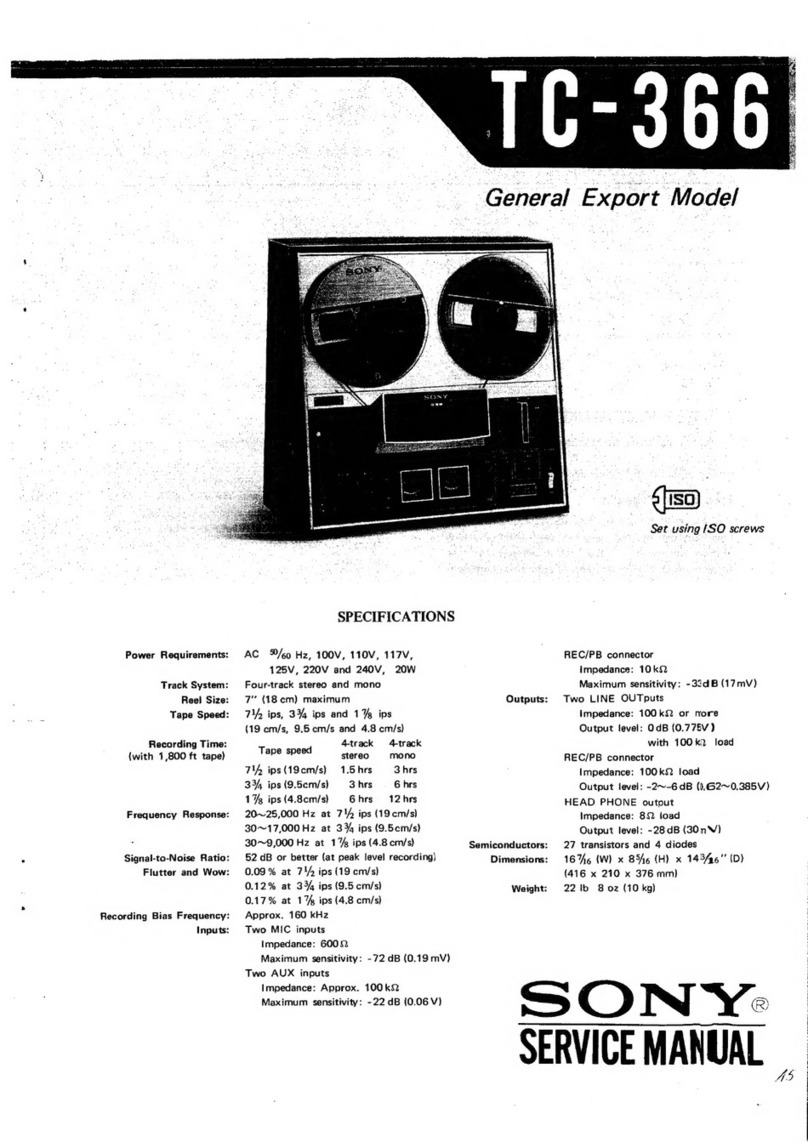
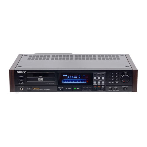
Sony DTC-300ES User manual

SERIJICE
MAIIUAL AEP
Model
ModelName Using Similar
MechanismDïC-U
|00
Tape Transport
Mechanism
TYPe DATU-
I2
SPECIFICATIONS
Tap€
Ro{ding hoad
Rording tiffi
TaF spo€d
Drum
totatioo
Ers co.t€did
t.Da
Oigitalaudiolap€
Rota.yhoâd
1æ minutes
(with
OT-120)
I 15m[Vs
Appror.2,000
Dm
DoubloReadSolomn code
Porerrequir€ments
Powerconsumption
Dimensions
Weight
220
v AC,50/60
Hz
35W
Approx470x 'l
15x 330
mm(Wh/d)
(18!ft
x4r/.x 12'l.inch€s)
ircl side
wood, proiælingparts
and
æntrols
ApproxI 0 kg ('|9lb 14
oz)
incl sidewood
T.âck
tttch
Sarçfng lGqrFæt
llot blid systm
TraÉld rals
tlrrù( ol .fi.m|
ry @fffi!.6
FGqFEy EâPon$
qlÉl toftis ,atio
oynanictang€
Tolâl
hempnic distonin
Wbwa.d iblter
hDUt
136
Fm(2O4
Fm)
48kHz.
441kHz,32kHz
I . lO tlodulâtin
2.46 Mbaus
2 cfianneb, stelæ
lÈUtliMt
2-22,000Hz tO 5 dB
Morelhan 90 dB
lilofe than90 dB
Ls$ then0.0085%
(t kHz)
B€lowmæuraue limit
($.00r% w PEAK)
n.mot. commândcr
(tupplbd)
F€moloænt.ol
system Inlriledænltol
Power
ræui.omonts 3V OC,withlrc R6
(size
AA)bstt€des
Oimensions Approx67x æ x '175
mm(WTVd)
(23l.
x !t/'. r 6'/. irches)
Wâight Approx
1409(5ozliæl banori€s
Suppllad!cær$?lct
Sonybanotios
SUM-3(NS)
(2)
Audioconn€cling
ærds (2phonodugs - 2 phono
plugs,
stor6o'lor
lineingulsandoutputs) (2)
Cleaning
€ssene (1)
. The sidewoodpan€lsonbothskj€sol thedæk il6 detachablg.
Forsatety.whenremovingthem,
bosurgto disconnocl
lheAC
powgrcordlrcm lha ACoutlet.
Designandspæifi€tions subjêct
tochangswithoulnolir
DIGITAL
AUDIO
TAPE
DECK
Jadr typa lmo€danc€ Raled Inouthvel
JNEIN phdro itd( '17
kohm -10dBs
)IGITALIN ptw iack 75ohms 0.5vp-9. 120%
)IGITALIN oplical Frcr
Jad( typo |mpadam Âatod
outpttt Load
impedaæ€
LINE
OIJT pluto !td( 470 ohm -10d&s Mdo then
10 kohms
HEAD.
Pr{oftEs stereo
ptffiFd( 220ohms t0 mW 32ohms
DGTTAL
OIJT opti(:al
iad 1660
nm
OETTAL
OIJT phdD iack 75otuns 0.5vPP
tN/. SONY

I
DTC-300ES I
Section Title
Location
and
Function
ofControls
TABLEOF CONTENTS
Page Section
SECTION1
GENERI\L
Specifications I
1.
GENERAL
Location
and Function
of Controls 2
2.D]SASSEMBLY
.. .........' 5
3. ADJUSTMENTS
3-
l. MechanicalAdjustments
.. ......... 8
3-2. ElectricalAdjustments..'.. ..'.....-L2
4. DIAGRAMS
4- 1. Block Diagram
- ServoSection '.......'.. 18
Title Pase
4-2. Block Diagram
- AudioSection '.
.....'.'. 2l
4-3. PrintedWiring Boards
- ServoSection ........... 26
4-4. SchematicDiagram
- ServoSection .........'. 3l
4-5. SchematicDiagram
- AudioSection ........... 35
4-6. Printed Wiring Boards
- AudioSection .'......... 39
5. EXPLODED
VIEWS ,.
".,. 44
6. ELECTRICAL
PARTS
LIST.' 55
SAFETY.RELATEDCOMPONENT
WARNINGI
I
coMpoNENTS TOENTTFIEDBy MARK l\ On OOrreO
L|NEW|THMARK a ON THESCHEMATTC
DTAGRAMS
ANO IN THE PARTS LIST ARE CRITICALTO SAFE
OPERATION. REPLACETHESECOMPONENTSWITH
SONY PARTSWHOSEPART NUMBERSAPPEARAS
SHOWNlN ÎHlS MANUAL OR IN SUPPLEMENTSPUB.
LISHED
BY SONY.
-2-

DTC-
300E
E POWER
swltch
Turns
the
power
onand
otf.
E] Cassette
comparlment
Insert
acassenewith
thewindowside
up
and
thesatety
tabfacing
you.
Ecourren bufions
MODE:Selects
thecounter
indicationin
the
display
window
amonglhe
linear
counter
(tape
running
time),
absolutetime,elapsed
timeoftheselection,
andtotal
remaining
timeotthetape.Each
time
youpress
the
butlon,
the
indication
changes
sequentially.
RESET:
Resets
lhe
linear
counterto"0M
00S".
Eil
Remotesensor
Receivesthesignalfrom
the
remote
commander.
Esrlnr tDbutons
AUTO:
Press
to
turnonthe
AUTO
indicator.When
the
AUTO
indicator
islit,
thestartlDwill
automaticallybe
written
during
recording.
When
the
recording
level
has
been.belowthefixedlevelformore
than
3
secondsand
then
returns
to
thefixed
level,
the
start
lDis
written
onthetape
tor
gseconds.
WRITE
(MANUAL
onthe
rernote
commander):Pressto
writethe
start
lD
atthedesired
point
during
recording
orplayback.
TheWRITEindicatorlights.The
start
lD
is
writtenonthe
tape
for
9secondstromthe
point
whenthebuttonis
pressed.
ERASE:
Press
toerase
astartlO,When
astart
lD
and
aprogram
number
are
written
onthe
tape,bothcodes
aresimultaneouslyerased
bypressing
thisbutton.
RENUMBEB:Presstorenumber
the
program
numbers.
When
only
thestart
lOs
arewritten,
pressing
this
butlon
will
insert
program
numbsrs.When
thisbutton
is
pressed,
th€tape
is
rewound
to
thebeginning
automaticallyand
program
numbers
areassigned
kom
"1"
in
numerical
order.
E Muslcselectbuttons
Numerlcbuttons
(G9):
Intherecord-pausemode,
press
thedesired
button
todesignatethe
program
number
you
want
to
write
tirst.
Also
designatethe
desired
program
numb€rtobe
played
backbefore
starting
playback
by
pressing
START.
CLEAR:Usedtocancel
the
program
numberwhichhas
beenentered
mistakenly.
ENO:
Press
to
write
th€end
lO
onth€
tap€.
START/MUSIC
SCAN:Presstostart
playback
of
the
selectiondesignated
bythe
numeric
button.
ln
the
stoporplayback
mode,
press
tolisten
tothe
beginningoteachselectionsuccessively
(music
scan).
E sxtp tD
buttons
WRITE:
During
recording
orplayback,press
at
the
beginningoflhe
portionyou
want
toskiplater.
The
SKIP
lD
andWRITEindicatorslightup
for
amoment
andtheskiplD
iswritientor1
second.
EFASE:
Press
toerase
askip
lD
which
iswrinen
at
th€
point
iust
b€fore
the
current
position.
The
ERASE
indicator
blinkswhile
th€
tap€
isrewound,
and
lights
upwhiletheskip
lDis
beingerased.
ON/OFF:
Setthis
button
loONtoskipduring
playback
the
portion
coded
with
askiplDcode.Set
ittoOFF
toplay
backthe
wholetap€asitis.
E REC
LEVEL
(recordlng
l€vel)
controls
Adjustthe
recording
levellortheanalog
input
signals.
The
outer
knob
controls
theL(left)
channellevel
andthe
inner
knobtheR
(righ$
channel
level.
Theknobscan
be
lurnedtogether.
Whan
recording
digitalsignals,
lhe
recordinglevel
cannotbeadjusted.
E xeAopnONES
lack
andLEVELcontrols
The
LEVELcontrols
adjustthe
headphones
volume
level.
@fape operatlon
buttons
I (stop):Press
tostoprecording
orplayback.
> (play):Press
toplay
back
thetape.
K< >DlAMS:Press
tolocate
thebeginning
ofthe
selection
during
playback.
<< >> (rewlnd/revlew,
tast-fotrard/cue):In
lhestop
mode,
press
torewind/fast-fomard
thetape. During
playback,
press
torewind
orfast-fonvard
the
tape
whilelistening
to
the
sound.
OREC:Press
) while
pressing
thisbutton
torecord.
ll PAUSE:
Press
to
stopfor
amomenl
during
playback.
Torestarl
playback,
press
this
buttonagain.
ll
the
pause
mode
continues
for
about10minutes,
it
will
bereleased
automatically
andthedeck
willenter
thestopmode.
OREC
MUTE
(record
mutlng):
Inserts
a sound-muted
portion
(space).
E e openlcLosE
butron
Presswhen
inserting
or
removing
thecassette.
E txPUf
selector
Set
inaccordance
with
thesignal
toberecorded.
ANALOG:
Forrecording
from
the
equipment
connected
to
theLINElN
jacks
DIGITAL:For
recording
from
the
equipment
connected
to
theDlcITAL
lN
jacks
ETIMER
swltch
Normally
set
toOFF. Used
tostart
recording
orplayback
atthedesiredtime
usinga
commercially
available
audio
timer.
[4 CDSYNCHRO
(CD
synchronlzedrecordlng)
buttons
STANDBY:
Press
tosetthe
unit
in
the
record-slandby
mode.
START:Presstostarlrecording
oftheDATdeck
and
then
playback
of
theCD
player.
STOP:
Press
tostoptheDAIdeck
recording
and
theCD
player
playback.
@CDoperatlon
buttons
Operativeonly
lor
the
Sony
CD
player
equipped
with
a
remotecomrnand€r.
ll (pause):
SetstheCD
player
in
the
pause
mode
during
playback.
Pressagain1orelease
pause.
lf
pressed
twicewhenthe
player
isin
fhestopmode,
playback
slarls.
K< >)l (AMS):
Press
to
locate
thedesired
selectionon
the
Compact
Disc
during
playback
or
in
thestop
mode.
-3-

Hear
Panel
Jacks
E ltHe lN
(line
input)
jacks
(phono
lack)
Connect
tothe
recordingoutputs
ofanamplifier.
The
signal
from
the
sourceequipment
connected
tothe
amplifier
is
supplied
to
this
deck,and
can
berecorded
with
thesampling
frequencyof
48kHz.
EIUHe
OUT
(line
outpu$
iacks
(phono
iack)
Connectto
the
DATor
tape
inputs
of
an
amplifier.
The
playback
signalofthis
deck
willbe
output.
BcoaxrauoPTlcAL DlclTAL
lN
(dlgltal
Input)
lacks
(phono
lacUoptlcallack)
The
digitalsignal
fromanother
DATdeckorotherdigital
source,suchas
aBStuner
havingdigital
outputs,
is
input
for
digital
recording.lfPROH
(copy
prohibition)
is
displayed,however,digital
recordingofthesourcesignal
is
notpossible.
lf
the
sampling
frequencyofthesource
signal
is
44.1kH2,
digital
recordingisnot
possible.
B colxnuoPTlcAL DIGITAL
ouT (dlglrat
outpur)
lacks
(phono
facUoptlcal
lack)
Thedigitalsignal
reproducedby
this
deck
isoutput
without
passing
bythe
D/Aconverterof
the
deck.
Connect
tothe
digital
inputofanother
DAT
deckto
perform
digital{o-digilal
dubbing.
E orcral INPUTsELEcroR
Selectsdigital
inputsignal.
COAXIAL:
Selectsth€equipmenl
connectedtothe
COAXIAL
lN
jack.
OPTICAL:
Selectstheequipment
connected
to
the
OPTICAL
lN
jack
-4-

NOTE
: Follow the disassembly procedure in the
O Removethe four M4S tight screws
(with rins).
@Remove
an M3
x I screw
(case).
O Remove the cas€.
DATM BLOCKASSY O BVTT3x8
MECHAN]SM
DECK
ASSY
O EVTT
3x8 o BVTT3X8
SECTION
2
DISASSEMBLY
numerical
order given.
MoroR @ I 2.6x3
DC MOTOR
O flexible board
DTC-
O bett
Turn gear
(P) O in tho dir€ctionof arrow
Q and move tho cassott€ holder in the
direction o{ arrow @.
@ motor
@
82.
6x5
G)DC motor
@ mechanism deck
O drum drive boerd
,
mechanism
\l
oî/.o
,/ t----1
assy MECHANISM
DECK
O 82xa
@ holcler (A)
@ drum drive board
, -tVt-"'t
\<t mechanism
deck
l-\
!7
O B2x6
-ù.----- @ B2.6x5

DTC-3OOES
DTC-300ES Test Mode
For DTC-300ES,
the internalCPU
modes
canbe displayed
for servicing
on the counter'ssix-segment
display.
The following modes
can be displayed:
. Mechanical çeration
(Mechanical microcomputer operation)
. Mechanical instruction
(Main microcomputer instruction)
. Operation,/çeration completion
. End sensor normavabnormal
. Cassette half existence
. OPEN/CLOSE
. Tape end (takeuP)/normal
. Tape end (supply)/normal
. A/B head RF existence
. WIDTH 1.5 times normal speed/NOT 1.5 times
normal speed
. Soft tape,/normal tape
. REC inhibit/OK
. Drum normal/abnormal
. Tray in/out
. TEST mode/NOT TEST mode
. Take-up end hold/NOT hold
. Tray loading normaVabnormal
. Position EJECT/NOT EJECT
To display the test modes, set the TIMER switch to
TIME PLAY and turn on the power switch while press-
ing the START ID WRITE and SKIP ID WRITE buttons.
The mechanical microcomputer then enters the test
mode. When the MODE switch is pressed,the modes are
changed as follows :
ABS TIME +PGM TIME +REMAINING +
REMAINING (Mechanical operation display model)
+Linear. counter + ABS TIME
(c) The
indicatordisplav
is described
below.
Using
indicators
O through
@, data
in the
nain
nicroconputer
is displayed
byfourbits
(hexadecinal).
(ltems
O, @, @, @, and
@ arerechanical
nicroconputer
dataand
@ is nainnicrocomputer
da
ta.)
(a)
(b)
Display
position Description
oMechanical operation
@Mechanical instruction (main
micro-
computer
to mechanical
microcomputer)
@
0
2
3
Operat
ion mode
End sensor (NORJIIAL/ENôffif,)
Cassette half (YES/NO)
oPEN (oPEN/eæE)
@0
t
3
Tape end take-up
Tape end supply
RF (NO RF/EF)
reeI (TOPlpR)
reeI (END/NOR)
NOR}IALSPEED/NOT
NORM'_SPEED)
o0
I
2
3
Tape (SOFT/NOEI'1AL)
REC
(INHIBIl/OI()
DRIYIERR
(DR[M NORM.ALlffi)
I Orlr (TRÂY lN/ôÎtf)
@0
I
2
FTEST
lEIDH
TIABF
PEJCT
(TEST MCDE
/M;MSTJYfôD'E- )
(TAKE'UP
E}ID
HOLD/FrTôT6)
(TRAY I,OADI}G NoRMAL/
ABTONMAT)
(EJ
ECr POSrr r
OÈ{/NôT-ffir
POS
ITIO|,t)
-6-

(d) Displey positions O and @ a"e shown below.
(The same data as in @ is displayed in @ at
all times with a slight detay.)
Cod
eDisplay Description
0
I
,
3
4
5
6
I
v
B
c
D
F
t-t
t_l
I
t
_l
t_
:,
_t
tl,
t_
_t
t:
Lt
-l
a
l1
It
t-lI
t
,_,
I
_,
t_l
t-
tr
Blank
FWDxI
FWD
x 2.5
FWDx 16
REC FWD
FF
FF SEARCH
FWDx 16 (measure)
QPEII/CLOSE
STOP
PAUSE
REV
x l6 (measure)
REW
REWSEARCH
REVxI
REVx 2.5
REV
x 16
(e) Operations in the TEST mode are described
below (as eompared with those in the normal
mode).
l) Cassette is not detected.
2) CAUTION indication does not sppear.
Make adjustmentsin the order of the stepsdescribed.
Usethe alignmenttapes
describedbelow.
TY-7111 (8-909-812-00)
TY
-7252 (8-909-822-00)
TY-7551 (8-909-814-00)
TY-30B (8-892-358-00)
Usethe torquemeters
described
below.
TW-7131
(8-909-708-71)
TW
- 723t (8-909-
708-72)
Initial settingsare as follows
:
TIMER OFF
I
2.
e
SKIP
INPUTselection
RECIevel
OFF
DIGITAL
MIN
HEADPHONE level MIN
COUNTER mode AUTO
4. Set the tape path adjustment rnode as describedbelow
The DTC-300ES cannot enter the tape path adjustment
mode from PLAY mode. When the AMS button ()f{)
is pressedusing a 1.5 times normal speed tape, the FS
(sampling frequency) indication changes to 32kHz and
the set enters the FWD mode. When the AMS button
(t<1{) is pressed,
it enters the REV mode. When the
former button is pressed
using a normal speed
tape,the
set enters the FWD x 16 mode. When the latter button
is pressed,
it enters the REV x 16 mode.
-7-

DTC-
300ES
sEcTtoN
3
ADJUSTMENTS
3-1. MECHANICAL
ADJUSTMENT
When replacing the drum, finely adjust the tape path (in l.b times normal speed FWD mode).
3-1-1. Tapc
Path
Fine-Adjustment
(x1.5 FWD
Mode)
Adjustment
l. Connect
CH-I of an oscilloscope
to pin@ of an offset
jig and CH-Z to pin
@ of the offset jig.
2. Connect
a 3.3k-ohmresistor
between
pins7 (GAIN2)
and 6 (GAIN l) of IC52b.
3. Connect
the offset jig as shownbelow.
L
INES
4. Turn on the power switch, insert alignment tape Ty-
725L,and put the set into the TEST mode.
5. Press the AMS (>>l) button.
6. Remove the YEL and RED leads of the offset jig and
adjust guides Sl and Tl so that the shape of the RF
signal waveform on the oscilloscope is close to a square.
7. Connect the YEL and RED leads of the offset jig, turn
the offset jig's volume control, and fix the RF signal
waveform to a half level. At that time, finely adjust
guidesSl and Tl again so that the shape
of the wave-
form is close to a square.
8. Turn the offset jig's volume control, slowly change the
RF signal waveform in the vertical direction,and check
that the waveform uniformly changes
in the horizontal
direction.
9. Removethe two leads (YEL and RED) of the jig from
cNTs1.
(l) Check
that peakvalue
(B) of the RF signal
wave-
form is 60mV or more.
(2) Checkthat the undershoot
level of the RF signal
waveform's
flat portion is within l0%.
10.If the specification
is not satisfied,
repeatSteps
3
through 9.
11.Check
that thereis no gapbetween
thetape
andlower
flangein guides
S2,T2, T3,and F. Checkthat no curl *
occurswhen the tape touches
the lower flange.
If there
is a gap or a curl occurs,
adjusteach
guide
according
to the adjustment
on the next page. -8-
Adjustment Location
:
Mechanical
guides
51 and T1
Guide Sl
A 4,/5
xo
Guide
T1
A' 4,/5 or less
B,/10 or less
t:î )--r tn
,-__-,F--
B,/10 or less
The curl indicates
the distortion
which occurs
on the
tapein the FWDmode.
When
light is shone
on the tape,
the curl can be viewed
morevisually.
ATF PRogE
ôqar |ôqrnpç
oFFSET JIG \ i::::=::::-:- SERVO BOARD
3-l-2. T2 GuideAdiustment
Adjustment
1. ConnectCH-l of anoscilloscopeto pin 5 (RF)
of CN542
on theservoboard
andCH-2 to pin 2 (SWP)
of CN542.
2. Turn on the power switch,insert alignmenttapeTY-
7252
@-9fJÉ-822-00),
and put the set into the TEST
mode. Press
the AMS button,then press
the PLAY
( ) ) button.
3. Raise
guideTl so that the RF signalwaveform
is as
shownbelow.
Raise guide T2 and alien it with the lower edge of the
tape.
Lower guide Tl so that the RF signal waveform is
normal.
Replace
the alignment tape by DT-120R and check that
the tape is aligned with the lower edge of guide T3
at the beginning of it. If it is not, repeat Step 4.
Adjustment Location:
Mechanism assembly
Guide
Tl
GuideT2
Guide T3
3-1-3. 52 GqideAdjustment
Adjustment ;
l. Turn on the power switch, insert blank tape TY-308
(8-892-358-00), and put the set into the PLAY (> )
mode.
2. Raiseguide 52 and align it with the lower edge of the
tape.
Note: Check that no tape curl occurs at guide 52 in the
REW (}}) mode.
Adjustment Location:
Mechanism assembly
Guide52
-9-

3-1-4. F GuideAdjustment
Adjustment :
1. Turn on the power switch, insert blank tape TY-30B
(8-892-358-00), and put the set into the PLAY ( > )
mode.
2. Align guide F with the lower edge of the tape.
Note : Check that the tape is aligned with the lower edge
of guide T3 without curl.
Adjustment Location :
Mechanism assembly
Guide F
Guide T3
3-1-5. 53 Guide
Adjustment
Adjustment
:
1. Turn on the powerswitch,
insert blank tape TY-308
(8-892-358-00),
and put the set into the PLAY ( > )
mode.
2. Align guide S3 with the lower edgeof the tape.
Note: Checkthat the tape is aligned
with the lower edge
of guide53 without curl.
Adjustment
Location
:
Mechanism
assembly
3-1-6. T3 Guide Adjustment
Adjustment :
1. Turn on the power switch, insert blank tape TY-30B
(8-892-358-00), and put the set into the PLAY ( > )
mode.
2. Align guide T3 with the lower edge of the tape.
Note : Check that the tape is aligned with the lower edge
of guide T3 without curl.
Adjustment Location :
Mechanism assembly
Guide T3
GuideS3
-10

3-1-7. Rotary EncoderAdjustment
Adjustment :
L Remove the rotary encoder.
2. Turn the geat at the back of the chassis shown in Fig.
A in the direction indicated by the arrow until the
capstan axis housing touches the pinch roller as shown
in Fig. B.
3. At that time, align the line in the rotary encoder's
gear
with mark and tentatively fasten the rotary encoder
(see
Fig. C). Screws (B 2x4)
AdjustmentLocation
:
Mechanism
assembly
Put the set into the TEST mode.
Alternately repeat the PLAY ( ) ) and STOP( I )
modesandcheckthat the pinchroller is pressed
against
thecapstanaxisin thePLAY ( ) ) mode
andthat the
capstanaxis housingtouchesthe pinch
rollerasshown
in Fig.B in the STOP
( I ) mode.
Then,tighten the screws.
If Step5 is not satisfied,
repeatSteps1 through5.
<Fig.
B>
4.
5.
<Fig. C> Rotary encoder I | ^ Capstan axis housing
e
Back of Rotary Encoder
/
3-l-8. Loading
Ring lnstallation
Combinethe loading ring (R) assemblyand loading ring
(L) assembly
with the portion crossedas shown in the
figure.
Insert into two ring rollers A.
Tighten the two screws while pushing the ring roller
assembly ln the direction indlcated by the arrow so
Loading ring (L) assembly
Rotate to check
Loading ring (L) assembly movement.
\_ _5.-. Ring rollers
.--à /
-/
-T- H
/
Loadingring (R) assembly
5.
Top View
<Fig.A>
Back of chassis
that ring roller B is aligned with the loading ring.
Slowly turn the loading ring and check that there is
no play.
Insert the two loading arms into the axes and fix them
using washers.
Washers
Loading rine G)
assembly
(Viewed from the back)
Loading ring (R) assembly
Mechanical chassis

Rv50r
(vco)
RVSIJP
ATF pilot
Rv505
A-GH
RV506
8-CH
3-2. ELECTRICAL
ADJUSTMENT
Adjustrnent Location :
Servo board (soldering side)
3-2-t. FWDTorguc
Adjurtment
Adjustment:
1. Turn on the power switch and insert FWD torque
meter
TW-?131.
2. Put the set into the PLAY ( ) ) mode.
3. Adjust RV504so that the FWD torque value (take-up
rewinding torque) is 10 to 13g cm.
4. Check the torque meter reading while it makesone
cycle.
AdjustmentLocation
:
Servoboard (solderingside)
3'2-2. FWD
Back
Tension
Adjustment
Procedure:
l. Turn on the power switch and insert FlryD torque
meter
TW-7131.
2. Put the set into the FWD ( ) ) mode.
3. Checkthat the back tension(at supply side)is 4.5 to
6.5g cm.
4. Checkthe torque meter readingwhile it makesa half
cycle.
AD board
(component
side)
tracking
tage
BV?01
(otlsÊt R)
Rv?02
(A0distortion
R)
Rvl0l (otfset t)
RVl02
(40
distortion L)
-12-

3-2-3. REVIEW
Torque Check
Procedure:
1. Turn on the power switch and insert FWD torque
meter TW- 7131.
2. Put the set into the TEST mode'
3. Put the set into the REVIEW ( > + 11 ) mode'
(Pressthe REW (<<) button continuouslv in the FWD
mode.)
4. Check that the rewinding torque at the supplv side is
15 to l8g cm.
5. If the torque value does not satisfy the specification'
short the tap of RVSUP or RVSDN and recheck'
6. After check,cancel the TEST mode'
Check Point :
Servo board (soldering side)
g'2-4. FF,/REW
Torque
Check
Procedure
:
1. Turn on the power switch and insert FF'IREW torque
meter
TW-7231.
2. Put the set into the TEST mode'
3. put the set into the FF (}}) and REW (<<) modes
and checkthat the torquevalue is 30 to 45g cm or
more.
4. After check,
cancel
the TEST mode'
DTC-
3-2-5. Tracking Voltage Adiustment
Adjustment :
1. Connect a digital tester between pin 6 of IC525 and
GND.
2. Turn on the power switch, insert blank tape TY-308'
and put the set into the STOP ( I ) mode'
3. Àdjust RV509 so that the tester reading is 2'9V * SmV'
Note : When performing the tracking voltage adjustment'
besure to adjust the capstanspeed
at x 1 and x1'5'
Adjustment Location:
Servo board (soldering side)
3-2-6. CapstanSpeed Adiust."nl (x l)
Adjustment :
1. Connect a frequencv counter to pin ? (CFG) of IC516'
2. Turn on the power switch, insert blank tape TY-30B'
and put the set into the PLAY ( ) ) mode'
3. Adjust RV508 so that the frequency counter reading is
674 X lHz.
Note: When performing the capstan speed adiustment
(x 1), be sure to adjust the capstanspeed
at (x 1'5)'
Adjustment Location
:
Servo board (soldering side)
- 13-

3-2-7. Crpstan
Speed
Adjurtment
(x1.5)
Adjustment:
l. Connecta frequencycounterto pin 7 (CFG)
of IC516.
2. Turn on the power switch,insert blank taæ TY-308
(for 1.5times normal speed),and put the set into the
PLAY ( )) mode.
3. Adjust RV507so that the frequencycounterreadingis
l0ll ! 2Hz
Note: Whenthe recognitionhole of blank tape TY-30B
is opened,the set is put into the 1.5times normal
speed
mode. When the hole is blockedusing an
adhesivetape,the modeis changedfrom 1.5times
normal speed
to normal speed.
TY
_3OB
Adjustm€nt Location
:
Servoboard (solderingside)
3-2-8. CapstanSpeed
Check
(x2.5)
Procedure:
1. Connecta frequencycounter to pin 7 (CFG)of IC516.
2. Turn on the power switch,insert blank tape TY-308,
and put the set into the CUE ( > + rù ) mode.
(Press
the FF (>>) button continuously
in the PLAY
mode.)
3. Check that the frequency counter reading is 1685t
150H2.
3-2-9. CepctenSpeed Check (x 16)
Procedure:
1. Connect an oscilloscope to pin 3 (PCOT) of IC518.
2. Put the set into the TEST mode.
3. Turn on the power switch, insert blank tape TY-308,
and put the set into the PLAY PAUSE ( > + ll )
mode. Then, continuously press the FF (>>) or REl{
(<1; 6u11.t.
4. Check that the signal waveform on the oscilloscope is
as shown below
'-
0v
A is less than 40% of B.
Recognition hole
OC
-14-

3- 2- 1
1. VCO Adjustment
Adjustment :
1. Unsolder tap pattern @ on the main board and open
it.
2. Connect CH- I of an oscilloscope
to TP501 and CH-2
to TP502.
(Connect the trigger of the oscilloscope
to SWP (pin 2
of CN542).)
3. Turn on the power switch, insert a music tape,
put the
set into the TEST mode, and put it into the PLAY
mode. (Any music tape can be used.)
4. Adjust RV503 so that the DC potential difference at
TP5O2is approximately -2.0V.
5. Adjust RV502 so that the signal waveform at TP501
satisfies the specification.
-,\-rlt\+ -{*-++
Adjust RV501 so that the signal waveform at TP501
satisfies
the specification.
Make flat.
7. Put the set into the CUE mode and finely adjust RV502
so that the signal waveform at TPSOI satisfies the
specification. (The specified waveform is the same as
in Step 6.)
8. Put the set into the REVIEW mode and finely adjust
RV50l so that the signal waveform at TP50l satisfies
the specification.
(The specified waveform is the same as in Step 6.)
9. Alternate putting the set into the CUE and REVIEW
modes two or three times and check that the siSnal
waveform at TP501 satisfies the specification. (The
specified waveform is the same as in Step 6.)
10. Turn off the power switch and solder-bridge the tap
pattern.
11. Turn on the power switch and put the set into the
PLAY ( )) mode again.
12. Readjust RV5O3 so that the signal waveform at TP50l
satisfies the specification. (The specified waveform is
the same as in Step 6.)
N6
13. Put the set into the CUE mode and finely adjust RV503
so that the signal waveform at TP50l satisfies the
specification.
14. Put the set into the REVIEW mode and check that the
signal waveform at TP501 satisfies the specification.
- - -
\1
\-.-\ should be decreased
o.BV
in REVIEW mode and
0.1V in PLAY mode.
15. Put the set into the PLAY mode and check the signal
waveform at TP501. (The specified waveform is the
same as in Step 6.)
16. Put the set into the FF AMS and REW AMS modes
and check the signal waveforms at TP501 and TP502
(in the 16 times normal speed mode).
Af trfr #nsor
-TPs02
17. Set the TEST mode to OFF, put the set into 'the FF
AMS and RE\4/AMS modes,and check the signal wave-
forms at TPSOI and TP5O2 (in the AMS mode).
6.
p5g1
Voltages deflect significantly in
the positive (+) direction.
TP5O2
TPsOI
Adjustment
Location
:
Servoboard
(solderingside)
Servo board (Soldering side)
TP5O2
'l"ruo,
- 16-

3-2-9. DPG
Adjuetment
Adjustment:
l. Connect
CH-l of an oscilloscope
to the emitterpin (RF)
of Q550and CH-2 to pin 20 (DPG)of IC515'
2. Select
tap pattern I and makea solderbridge to check
the originaldelayvalueof a PGpulse. (The delaytime
of one DPGSW code is approximatelv100
p sec')
3. Turn on the power switch,insert aliSnment
tape TY-
7251,
and put the set into the TEST mode'
4. Pressthe AMS button, then press the PLAY ( > )
button.
5. Selectthe tap pattern so that the trailing edges
of a
DPG
pulse
and RF signal's
non-sigral areapproximately
650
p sec.
(Coarse
adjustment)
High-order4 bits (taps4,5' 6' and 7)
6. Put the set into the PLAY ( ) ) modeand selectthe
tap pattern so that the DPG and RF signalson the
oscilloscope
are 650 + 15
p sec.
Then,finelv adjust the
DPGPulsewidth.
Low-order bits (tapsO,L'2' and 3)
Note: Whenreplacingthe drum relatedblock' be sure to
perform the DPGadjustment.
Servoboard (soldering
side) Low-order
4-bit tap
High- order
4-bit tap
3-2-10. ATF PilotAdiurtment
Adjustment:
1. Connect
CH-I of an oscilloscope
to pin 8 (S,/H3) of
rc5z3.
connectcH-2 of an oscilloscope
to pin 2 (swP) of
cN542.
(TRICCER)
2. Turn on the power switch,insert alignmenttape TY-
?111,
and put the set into the STOP
( I ) mode.
Then'
put the set into the TEST mode.
3. Align the luminescent
spot on the oscilloscope
with the
scalecenterposition. (Never align the spot with the
center position when the input is set to GND.)
4. Put the set into the PLAY ( ) ) mode
andadjustRV505
(A-cH) and RV506
(B-cH) so that the siSnal
wave-
form is 600mV after two or three seconds.
DC range
500mV,/D
I V
(Center
scale)
a-cll. E-c)l
Note: If the signal waveform deflectsvertically,adjust it
in the deflectioncenter.
Adjustment Location
:
Servoboard (solderingside)
(Reference)
AdjustmentPoint
Servoboard (solderingside)
- 15-
DP6
Tap pattern
o/c t/t V6 7t
c)
o
I
È
b0
o)
o
F
a
Êi
A
o
2o
3oo
ao
3oo
6oo
Ioo o
6o
9oo
^oo
Iooo
coo
oo o o
Eo o o
fooo o

3-2-12. AD DC Offset Distortion Factor Adjustment
Adjustm€nt :
l. Set the INPUT select switch to ÀNALOG and input a
tkHz (OdB) signal.
2. Connect an oscilloscope to the LINE OUT terminal,
TPl50 (L-CH), and TP250 (R-CH).
3. Turn on the power switch and insert blank tape TY-
308.
Put the set into the REC mode.
Turn the REC volume control until the OVER indicator
blinks and adjust RVlOl (L-CH) and RV20l (R-CH) so
that the LINE OUT signal waveform is uniformly
clipped in the vertical direction.
Attenuate the input signal and fully turn RV102
(L-CH)
and RV202 (R-CH) counterclockwise so that the signal
waveforms (integrated waveforms) at TPl50 (L-CH) and
TP25O(R-CH) are as shown in Fis. @. After that,
gradually turn them clockwise until the signal wave-
forms shown in Fig. @ are obtained.
I DTC-300E1
@Nc
l- R-C ll t_
@uc
@nc
4.
o.
^
L9
7. RepeatStep 5.
8. Turn the FEC volumecontrol so that the signalwave-
form is as shown in Fig. @ when the level meter @
reading is approximately- 55. Then, slightly turn
RV102and RV202clockwiseso that the signal wave-
form is as shown in Fig. @.
Dstortion factor (reference)
: -8O.5dBor less (lkHz
full-scale,20kHz LPF ON)
Adjustm€nt Location
:
AD board (component
side).
DTC_
3OOES
oooD @
No good if gap occurs.
LINE OUT
DTC_
3OOES Oscilloscope
-17 -

DTC-300ES I
IsEcTloN
4
4-I. BLOCKDIAGRAM-SERVO
SECTION_ DIAGRAMS
0Ruil
I€TM PG
DRW
MTOff FG
cÂsstTrE
DETECI
st <:o-!ll!--
REc
Ettaf,ED€IEC1
Sw
<\o-j!!SI--
CÂSSETT€
TÂBLEDOM D€TECTSW
CASSETTE
TÂ8LE OUT DETECTSW
uilLsDrt*G Ltt{l oElEcT
sr
- 18-

-z
-4
i::ËËË
rÀTf
-=ri:i
FFJHUP
cÂP0rR
TOP
TLED
tr0
SLTD
M903
L0Â0rt{G
PINCH
Oil/OFF
MOTOR
II)ÂUDO
ELOCX
XRST
t5TW
- 19-

6\ Mso4
\;/ oRU*rOToR
Table of contents
Other Sony Tape Deck manuals

Sony
Sony TC-366 User manual

Sony
Sony DTC-700 User manual

Sony
Sony TC-765 User manual

Sony
Sony DTC-790 User manual

Sony
Sony DTC59ES User manual

Sony
Sony TC-378 Setup guide

Sony
Sony TC-765 Setup guide

Sony
Sony PCM-R500 - Dat Recorder User manual

Sony
Sony PCM-R500 - Dat Recorder User manual

Sony
Sony TC-854-4 User manual

Sony
Sony DTC-77ES User manual

Sony
Sony DTC-700 User manual

Sony
Sony TC-366 User manual

Sony
Sony DTC-87ES User manual

Sony
Sony DTC-670 User manual

Sony
Sony DTC-A8 User manual

Sony
Sony PDW-F1600 User manual

Sony
Sony DTC-60ES User manual

Sony
Sony DAT DTC-690 User manual

Sony
Sony MDS-JA50ES / Mode d’emploi User manual