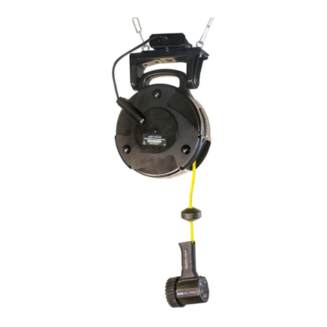
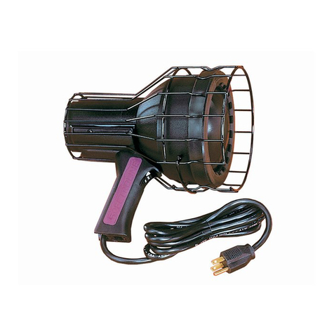
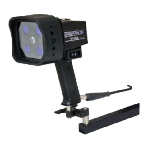
Spectroline uVision Series User manual

1
6/22 AM18013ML-5
PRINTED IN U.S.A
uVision™ Series
UV-A/White Light LED NDT Inspection Lamp
Part No. UV-365HCR
www.Spectro-UV.com
4 Dubon Ct., Farmingdale, NY 11735
866-230-7305
ENG - 1 FR - 9 ES - 17 DE - 25

2 3
CHANGING THE LAMP POWER SUPPLY
The appropriate cord for the country of destination will be installed on the lamp when it is
ordered. The power cord is integrated into the lower portion of the lamp handle, forming a
cord/handle assembly. A set of detailed instructions for changing the lamp cord come with
the replacement parts. Contact Customer Service for more details. Call toll-free 1-866-230-
7305.
WARNING
UV emitted from this product. Avoid eye and skin exposure to unshielded products.
FOR PROFESSIONAL EXAMINATION USE ONLY
OPERATION
• The uVision™ series UV-A inspection lamps are equipped with a heavy-duty power
cord.
• The lamp is shipped with the correct cord installed for the country of destination.
• Connect the plug to a power source that complies with the electrical requirements
specified on the label.
• The lamp has a three-position rocker power switch (II – UV; O – off; I – white light) on
the handle.
• WARNING: Be sure to use genuine uVision™ replacement parts. Using another
manufacturer’s replacement parts could affect product performance and will void the
warranty.
• The UV-365HCR White Light Intensity Adjustment Controls are located on the back
plate of the lamp. Select the preferred white light intensity setting. The Power Indicator
is also located on the back plate of the lamp.
Rocker Switch
Power
Indicator
White Light
Intensity
Adjustment
DISASSEMBLING THE FILTER PROTECTOR FOR MAINTENACE
The outer rubber cover/filter holder may be removed periodically to clean the Borofloat®
glass filter. To disassemble the Borofloat®Filter Protector (FP-600), first remove the front
rubber cover/filter holder. Peel the rubber cover/filter holder toward the front portion of the
lamp.
The Borofloat®glass filter will remain inside the protector. To remove the Borofloat®glass
filter, peel around the edge of the rubber cover/filter holder and push the glass filter out.
To replace or reinsert the Borofloat®glass filter into the rubber cover/filter holder, slide the
Borofloat®glass filter into the channel of the rubber cover/filter holder. Manipulate the rubber
cover around the filter. Ensure the glass filter is evenly seated.
REPLACING THE UV LENSES
The UV-A lenses (UL-110) covering the three UV-A LEDs must be replaced over time. They
will solarize (become cloudy and yellow) from repeated use. A set of detailed instructions
come with the replacement UV-A lenses (UL-110). See Replacement Parts section and
contact Customer Service for more details.
ENVIRONMENTAL SPECIFICATIONS
The uVision™ series lamps are designed to be safe under the following conditions:
• For Indoor/Outdoor Use (dustproof and protected against jets of water);
• Temperature 41°F to 122°F (5°C to 50°C);
• Mains supply voltage fluctuations not to exceed ±10% of the nominal voltage;
LIMITED WARRANTY
The warranty policy for the uVision™ lamp is provided on the Certificate of Limited Warranty
enclosed separately with each unit. NOTE: For assistance of any kind, please contact the
Customer Service Department at Spectro-UV. Provide the model, the serial number of the
unit, and the date of purchase. The unit’s serialization information is located (1) on the
packaging the unit is shipped in, (2) engraved on the unit’s handle, and (3) labeled on the
reverse side of the unit’s back plate.
BATTERY LED INDICATOR STATUS
Orange = Power on, battery good
Blink Orange and Red = Low Battery; time left approx. 10 – 15 mins
Red = Dead Battery, Approx. 5 minutes or less remaining
Shut Down
IMPORTANT SAFETY INSTRUCTIONS (Read all instructions)
• Do not operate the uVision™ Series UV-A/White Light LED NDT Inspection Lamp
(UV-365HCR) with a damaged cord or if the lamp has been physically damaged.
• Do not look directly into the light. ALWAYS wear the UV-absorbing protective glasses
provided when operating the lamp. Use in low-light conditions to achieve the best
inspection results. The darker the room, the greater the fluorescent contrast.
• The uVision™ is not approved for use in hazardous atmospheres. Do not attempt to use
it in areas requiring explosion-proof lighting.
• Never use this equipment in any manner not specified in these instructions because
your protection may be impaired.
• NEVER aim the lamp in the direction of another human being. It is meant for
professional fluorescent inspections ONLY!
• DO NOT attempt to modify the lens assembly or light output. Doing so may alter the
performance and intensity of the uVision™.

4 5
KEY FEATURES
• 50 Foot (15 Meter) Retractable Power Cord Reel
• Nominal steady state intensity of 6,000 µW/cm2at 15 inches (38cm).
• Large 6.4-inch diameter coverage area at 15 inches (38cm) with a minimum UV-A
intensity of 1,200 µW/cm2(ASTM E3022-15).
• Less than 1.0 foot-candle (11 lux) emission.
• Long-lasting UV-A lenses.
• Cool running, fanless design.
• Lightweight and rugged construction.
• White Light, LED Inspection Light.
• IP65 Rated: The uVision™ Series lamps are protected from total dust ingress and
from low pressure jets of water (from all directions). For more details, consult EN 60529
(British BS EN 60529:1992, European IEC 60509:1989).
• Certificate of Conformance (ASTM E3022-15) included.
TECHNICAL SPECIFICATIONS
uVision™ Series
UV-365HCR UV-A (365nm) and white light
Height 7.5 inches
Length 4.25 inches
Width 3.75 inches
Weight 15.45 lb. (including Reel and Power Supply)
Light Source 3 UV-A LEDs, 1 white light LED
ELECTRICAL SPECIFICATIONS
Input: 100-240V AC, 0.9, 50-60 Hz
Output: 15V DC, 2.4A
POWER CORD SPECIFICATIONS
LAMP PART NUMBER POWER REQUIREMENTS*
UV-365HCR 120V/50–60Hz
UV-365HCR/F 230V/50Hz
UV-365HCR/FA 240V/50Hz
UV-365HCR/FB 230V/50Hz
UV-365HCR/FBR 220-240V/50-60Hz
MEASURING LAMP INTENSITY
To ensure that your uVision™ series lamp is operating at the required UV intensity, it should
be checked periodically. Spectro-UV offers a variety of sensors and meters.The AccuPRO™
XP-2000 combines the functionality of a UV and visible light radiometer/photometer, and is
specially designed to measure UV irradiance with wavelengths of 320–400nm (with peak
at 365nm) and visible light from 460–675nm (with peak at 555nm). Other suitable meters
include the AccuMAX™ XRP-3000 radiometer/photometer kit, using dual-wavelength
UV-A and VIS sensor detectors to accurately measure the irradiance of a light source. The
AccuMAX™ XR-1000 digital readout unit with the XS-365 UV sensor or the DM-365XA
digital readout unit can also be used for UV-A measurement. For more information about
these units, please contact the Customer Service Department at Spectro-UV. Call toll-free
1-866-230-7305.
1
1
2
2
3
3
4
4
A A
B B
WESTBURY, NEW YORK 11590
956 BRUSH HOLLOW ROAD
CORPORATION
SPECTRONICS
REV
DRAWING NUMBER
SIZE
DATE
DATE
DATE
APPROVED
CHECKED
DRAWN
TITLE
NEXT ASSY.
NO. REQ'D
SCALE
30'
.005
ANG.DEC.
UNLESS OTHERWISE SPECIFIED
DIMENSIONAL TOLERANCES
FRAC.
1/64
+
- -
+-
+
FILE NAME & PATH
PROPERTY OF SPECTRONICS CORP; DO NOT DUPLICATE
MATERIAL FINISH SPECTRONICS PART NO.
1
A-18103
B
PHILIPC
11/8/2017
UV-365HCR
MANUAL
C:\Engineering\Projects\TRITAN\Ultravision 365\A-18103, UV-365HCR, ASSEMBLY, MANUAL.idw
UV-365HCR
BP 2 3 4 5
UV-365HCR REPLACEABLE PARTS LIST
ITEM QTY PART NO. DESCRIPTION
1A 1 130405 POWER SUPPLY, REEL, 50FT, UVISION, 120V, US
1B 1 130406 POWER SUPPLY, REEL, 50FT, UVISION, 230V, EU
1C 1 130407 POWER SUPPLY, REEL, 50FT, UVISION, 240V, AU
1D 1 130408 POWER SUPPLY, REEL, 50FT, UVISION, 230V, UK
BP 1FP-600 FILTER PROTECTOR ASSEMBLY
2 1 128196 FRONT COVER PLATE/ FILTER ASSEMBLY
3 1 128385 FRONT COVER GASKET
4 3 129427 UV LED LENS, WITH ADHESIVE
5 1 130336 LAMP HOUSING ASSEMBLY
1A
1B
1C
1D
UV-365HCR EXPLODED VIEW
AND REPLACEMENT PARTS
QTY PART NO. DESCRIPTION
1 UVS-30 UV-ABSORBING SPECTACLES
Accessories
Replacement Parts
ITEM QTY PART NO. DESCRIPTION
1A 1 130405 POWER SUPPLY, REEL, 50FT, UVISION, 120V, US
1B 1 130406 POWER SUPPLY, REEL, 50FT, UVISION, 230V, EU
1C 1 130407 POWER SUPPLY, REEL, 50FT, UVISION, 240V, AU
1D 1 130408 POWER SUPPLY, REEL, 50FT, UVISION, 230V, UK
1E 1 130504 POWER SUPPLY, REEL, 50FT, UVISION, 220-240V, BR
BP 1 FP-600 BOROFLOAT®FILTER PROTECTOR ASSEMBLY
2 1 128196 FRONT COVER PLATE / UV-A FILTER ASSEMBLY
3 1 128385 FRONT COVER GASKET
4 3 UL-110 UV LED LENS, WITH ADHESIVE
5 1 130336 LAMP HOUSING ASSEMBLY
1A-1E

6 7
CORD REEL INSTRUCTIONS
INSTALLATION
Lamp-Ballasted Models (Ceiling Mount)
•Select a location within proximity to an electrical outlet.
•Suspend the lamp assembly from a suitable ceiling mount. Connect a chain to the ceiling
mount. Next, fasten the chain to the eyebolts located on the topside of the unit. Make
certain the unit is balanced.
OPERATION
• Connect the primary cord to a power outlet that complies with the electrical requirements
listed on the lamp.
• Pull the cord out to the desired length and stop. If the cord does not hold, continue to
pull the cord slowly, stopping every 4 inches (10 cm). This will engage the lock.To retract,
pull the cord out 2 to 4 inches (5 to 10 cm) and guide the cord slowly back into the reel.
• Do not pull hard on the cord when it is fully extended to 50 feet (15.2 m). This will cause
retracting spring to malfunction.
• Do not allow the cord to fly unrestricted back into the reel.
MAINTENANCE
• Remove dirt and grime as soon as it accumulates on the reel case. Wipe clean with a
dampened cloth. Do not use solvents such as gasoline, turpentine, etc., to clean the unit.
• Keep the cord clean to ensure the smoothest automatic retraction. Pull the cord to its
full length and allow it to retract through a clean, dampened cloth. Pull out the full length
again and allow it to retract through a clean, dry cloth sprinkled with talcum powder.
GENERAL SAFETY INFORMATION
• This unit should be used indoors. Do not use near potentially dangerous locations such
as flammable or explosive atmospheres or near water.
• Use only 3-wire extension cords that have 3-prong grounding plugs and 3-pole
receptacles that accept the unit’s plug.
• Disconnect the unit from the power supply before servicing or inspecting it for any reason.
WORK AREA SAFETY
Keep work area clean, dry, free of clutter, and well lit. Cluttered, wet, or dark work areas can
result in injury. Using the tool in confined work areas may put you dangerously close to other
cutting tools and rotating parts. Be aware of all power lines, electrical circuits, water pipes,
and other mechanical hazards in your work area. Some of these hazards may be below the
work surface hidden from your view and may cause personal harm or property damage if
unintentionally contacted.
ELECTRICAL GROUNDING
This reel must be grounded to protect the operator from electrical shock.The plug MUST be
plugged into a matching receptacle that is properly installed and grounded in accordance
with ALL local codes and ordinances. DO NOT MODIFY THE PLUG PROVIDED. If it will not
fit the receptacle, have the proper receptacle installed by a qualified electrician. CHECK with
a qualified electrician or service person if you do not completely understand the grounding
instructions, or if you are not sure the tool is properly grounded.
Eyebolts
Reel
50 ft. Power Cord
UV-365HCR Setup
www.Spectro-UV.com
4 Dubon Ct., Farmingdale, NY 11735
866-230-7305

8
Other manuals for uVision Series
3
This manual suits for next models
5
Table of contents
Languages:
Other Spectroline Lighting Equipment manuals

Spectroline
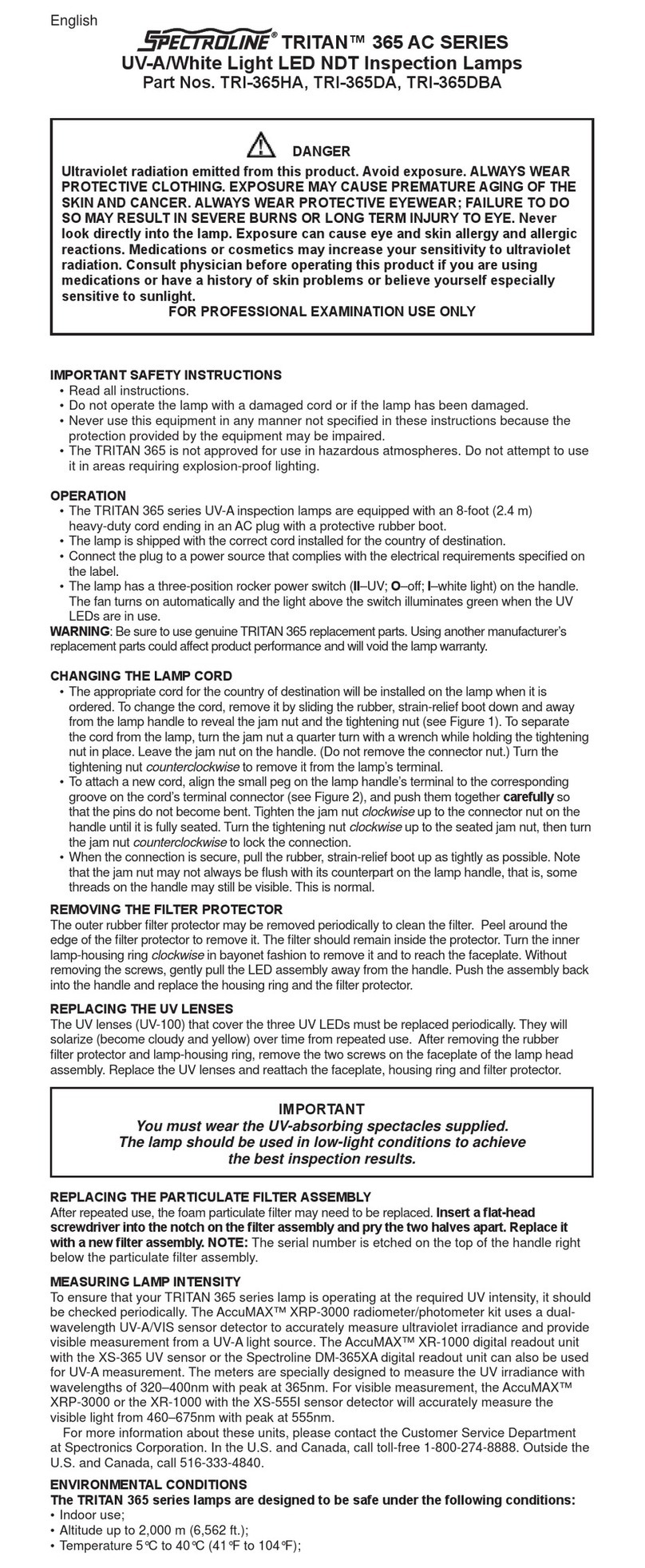
Spectroline TRITAN 365 AC Series User manual

Spectroline
Spectroline NANO 365 Series User manual

Spectroline
Spectroline uVision Series User manual

Spectroline
Spectroline uVision Series User manual

Spectroline
Spectroline BIB-150P/F/J Series User manual

Spectroline
Spectroline uVision Series User manual

Spectroline
Spectroline NANO 365 Series User manual

Spectroline
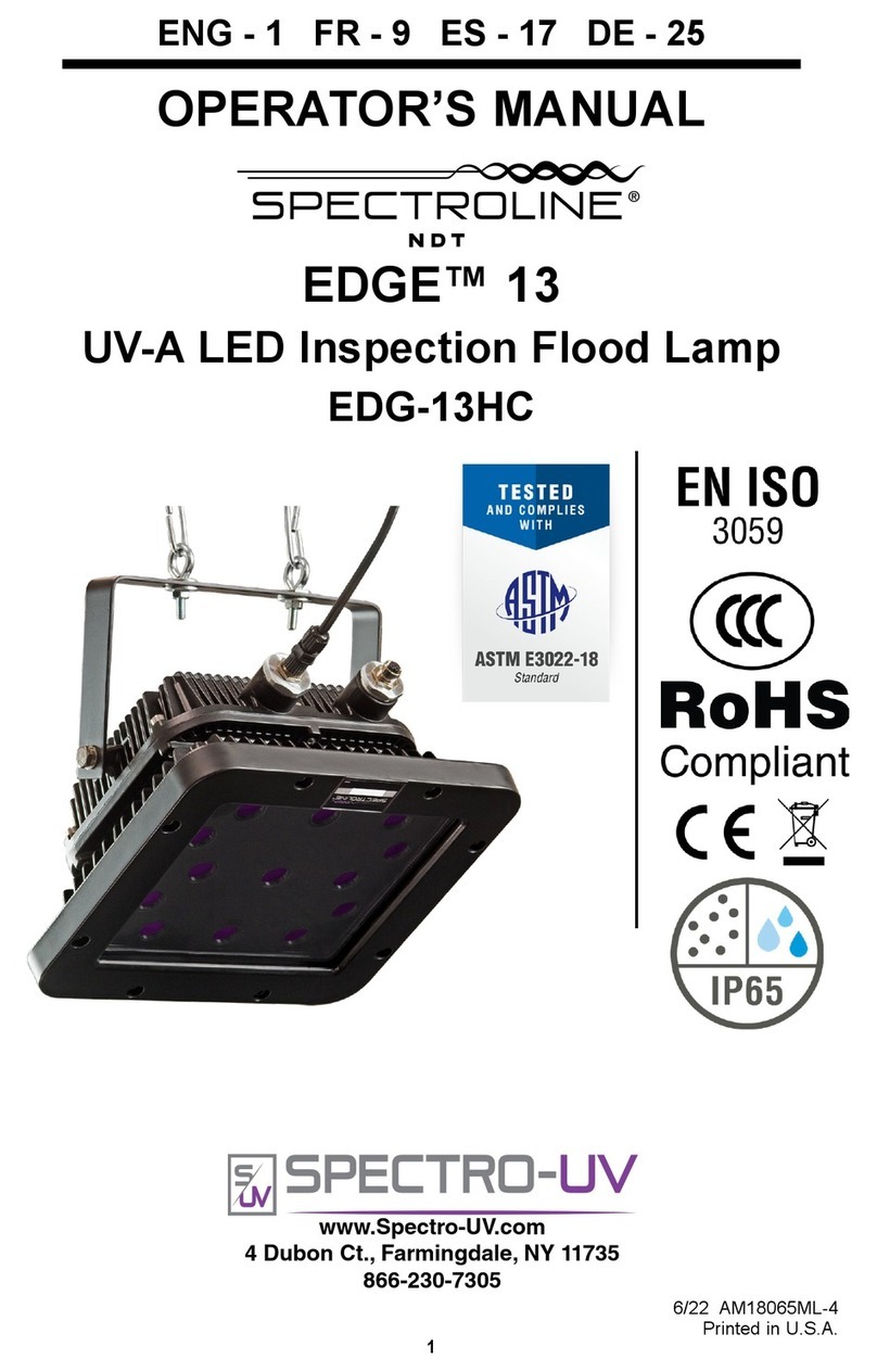
Spectroline EDGE 13 User manual

Spectroline
Spectroline NANO 365 Series User manual

Spectroline
Spectroline EDGE 13 User manual