Spectroline uVision Series User manual

1
7/20 AM18031ML-4
PRINTED IN U.S.A
uVision™ Series
UV-A/White Light LED NDT Inspection Lamp
Part No. UV-365SBLCR
www.Spectro-UV.com
4 Dubon Ct., Farmingdale, NY 11735
866-230-7305
ENG - 1 FR - 7 ES - 13 DE - 19

2
WARNING
UV emitted from this product. Avoid eye and skin exposure to unshielded products.
FOR PROFESSIONAL EXAMINATION USE ONLY
IMPORTANT SAFETY INSTRUCTIONS (Read all instructions)
• Do not operate the uVision™ Series UV-A/White Light LED NDT Inspection Lamp
(UV-365SBLCR) if the lamp has been damaged.
• Do not look directly into the light. ALWAYS wear the UV-absorbing protective glasses
provided when operating the lamp. Use in low-light conditions to achieve the best
inspection results. The darker the room, the greater the fluorescent contrast.
• The uVision™ is not approved for use in hazardous atmospheres. Do not attempt to use
it in areas requiring explosion-proof lighting.
• Never use this equipment in any manner not specified in these instructions because
your protection may be impaired.
• NEVER aim the lamp in the direction of another human being. It is meant for
professional fluorescent inspections ONLY!
• DO NOT attempt to modify the lens assembly or light output. Doing so may alter the
performance and intensity of the uVision™.
OPERATION
• The uVision™ series UV-A inspection lamps are equipped with a 50 ft. (15.3 m) heavy-
duty power cord and retractable reel.
• The lamp is shipped with the correct cord installed for the country of destination.
• Connect the plug to a power source that complies with the electrical requirements
specified on the label.
• The lamp has a three-position rocker power switch (II – UV; O – off; I – white light) on
the handle.
• The UV-365SBLCR has a White Light Intensity Adjustment Control located on the back
plate of the lamp. The Power Indicator is also located on the back plate of the lamp.
The Power Indicator light will be Orange when the lamp is operating within RRES
compliance.
• The UV-365SBLCR is designed to automatically shut off if the unit operates outside of
RRES compliance standards. To turn the unit back ON from a shut off event, turn the
lamp OFF and then ON using the three-position rocker switch.
• WARNING: Be sure to use genuine uVision™ replacement parts. Using another
manufacturer’s replacement parts could affect product performance and will void the
warranty.
Rocker Switch
Power
Indicator
White Light
Intensity
Adjustment
CHANGING THE LAMP POWER SUPPLY
The appropriate cord for the country of destination will be installed on the lamp when it is
ordered. The power cord is integrated into the lower portion of the lamp handle, forming a
cord/handle assembly. A set of detailed instructions for changing the lamp cord come with
the replacement parts. Contact Customer Service for more details. Call toll-free 1-866-230-
7305.

3
DISASSEMBLING THE FILTER PROTECTOR FOR MAINTENACE
®
®
lamp.
®®
®
®
REPLACING THE UV LENSES
The UV-A lenses (UL-110) covering the three UV-A LEDs must be replaced over time. They
will solarize (become cloudy and yellow) from repeated use. A set of detailed instructions
come with the replacement UV-A lenses (UL-110). See Replacement Parts section and
contact Customer Service for more details.
ENVIRONMENTAL SPECIFICATIONS
• For Indoor/Outdoor Use (dustproof and protected against jets of water);
• Temperature 41°F to 122°F (5°C to 50°C);
LIMITED WARRANTY
Customer Service Department at Spectro-UV. Provide the model, the serial number of the
unit, and the date of purchase. The unit’s serialization information is located (1) on the
packaging the unit is shipped in, (2) engraved on the unit’s handle, and (3) labeled on the
reverse side of the unit’s back plate.
BATTERY LED INDICATOR STATUS
Orange = Power on, battery good
Shut Down

4
MEASURING LAMP INTENSITY
To ensure that your uVision™ series lamp is operating at the required UV intensity, it should be
2000 combines the functionality of a UV and visible light radiometer/photometer, and is specially
measurement. For more information about these units, please contact the Customer Service
Department at Spectro-UV. Call toll-free 1-866-230-7305.
KEY FEATURES
• Nominal steady state intensity of 4,500 µW/cm2at 15 inches (38cm).
• Large 6-inch diameter coverage area at 15 inches (38cm) with a minimum
UV-A intensity of 1,200 µW/cm2(ASTM E3022-15 / Rolls Royce RRES 90061).
•
• Long-lasting UV-A lenses.
• Cool running, fanless design.
• Lightweight and rugged construction.
• White Light, LED Inspection Light.
• uVision™ Series lamps are protected from total dust ingress
and from low pressure jets of water (from all directions). For more details,
•
• Validation Report (Rolls Royce RRES 90061) included.
TECHNICAL SPECIFICATIONS
uVision™ Series
UV-365SBLCR UV-A (365nm) and white light
Height 7.5 inches
Length 4.25 inches
Width 3.75 inches
Weight 1.94 lb. (880 g) without power supply.
Light Source 3 UV-A LEDs, 1 white light LED
ELECTRICAL SPECIFICATIONS
UV-365SBLCR Technical Details
POWER CORD SPECIFICATIONS
POWER REQUIREMENTS*

5
1
1
2
2
3
3
4
4
A A
B B
WESTBURY, NEW YORK 11590
956 BRUSH HOLLOW ROAD
CORPORATION
SPECTRONICS
REV
DRAWING NUMBER
SIZE
DATE
DATE
DATE
APPROVED
CHECKED
DRAWN
TITLE
NEXT ASSY.
NO. REQ'D
SCALE
30'
.005
ANG.DEC.
UNLESS OTHERWISE SPECIFIED
DIMENSIONAL TOLERANCES
FRAC.
1/64
+
- -
+-
+
FILE NAME & PATH
PROPERTY OF SPECTRONICS CORP; DO NOT DUPLICATE
MATERIAL FINISH SPECTRONICS PART NO.
1
A-18103
B
PHILIPC
11/8/2017
UV-365HCR
MANUAL
C:\Engineering\Projects\TRITAN\Ultravision 365\A-18103, UV-365HCR, ASSEMBLY, MANUAL.idw
UV-365HCR
BP 2 3 4 5
UV-365HCR REPLACEABLE PARTS LIST
ITEM QTY PART NO. DESCRIPTION
1A 1 130405 POWER SUPPLY, REEL, 50FT, UVISION, 120V, US
1B 1 130406 POWER SUPPLY, REEL, 50FT, UVISION, 230V, EU
1C 1 130407 POWER SUPPLY, REEL, 50FT, UVISION, 240V, AU
1D 1 130408 POWER SUPPLY, REEL, 50FT, UVISION, 230V, UK
BP 1FP-600 FILTER PROTECTOR ASSEMBLY
2 1 128196 FRONT COVER PLATE/ FILTER ASSEMBLY
3 1 128385 FRONT COVER GASKET
4 3 129427 UV LED LENS, WITH ADHESIVE
5 1 130336 LAMP HOUSING ASSEMBLY
1A
1B
1C
1D
UV-365SBLCR EXPLODED VIEW
AND REPLACEMENT PARTS
QTY PART NO. DESCRIPTION
1 UVS-30
Accessories
ITEM QTY PART NO. DESCRIPTION
1A 1 130405 POWER SUPPLY, REEL, 50FT, UVISION, 120V, US
1 130406 POWER SUPPLY, REEL, 50FT, UVISION, 230V, EU
1C 1 130407 POWER SUPPLY, REEL, 50FT, UVISION, 240V, AU
1D 1 130408 POWER SUPPLY, REEL, 50FT, UVISION, 230V, UK
1E 1 130504
1 FP-600 ®
2 1 128196
3 1 128385
4 3 UL-110 UV LED LENS, WITH ADHESIVE
5 1 130336
Replacement Parts
1A-1E

6
CORD REEL INSTRUCTIONS
INSTALLATION
•
• Suspend the lamp assembly from a suitable ceiling mount. Connect a chain to the ceiling
certain the unit is balanced.
OPERATION
• Connect the primary cord to a power outlet that complies with the electrical requirements
listed on the lamp.
• Pull the cord out to the desired length and stop. If the cord does not hold, continue
to pull the cord slowly, stopping every 4 inches (10 cm). This will engage the lock. To
retract, pull the cord out 2 to 4 inches (5 to 10 cm) and guide the cord slowly back into
the reel.
•
retracting spring to malfunction.
•
MAINTENANCE
• Remove dirt and grime as soon as it accumulates on the reel case. Wipe clean with a
dampened cloth.
• Do not use solvents such as gasoline, turpentine, etc., to clean the unit.
• Keep the cord clean to ensure the smoothest automatic retraction. Pull the cord to its
full length and allow it to retract through a clean, dampened cloth. Pull out the full length
again and allow it to retract through a clean, dry cloth sprinkled with talcum powder.
GENERAL SAFETY INFORMATION
• This unit should be used indoors. Do not use near potentially dangerous locations such
•
receptacles that accept the unit’s plug.
• Disconnect the unit from the power supply before servicing or inspecting it for any
reason.
WORK AREA SAFETY
Keep work area clean, dry, free of clutter, and well lit. Cluttered, wet, or dark work areas can
and other mechanical hazards in your work area. Some of these hazards may be below the
work surface hidden from your view and may cause personal harm or property damage if
unintentionally contacted.
ELECTRICAL GROUNDING
This reel must be grounded to protect the operator from electrical shock. The plug MUST be
plugged into a matching receptacle that is properly installed and grounded in accordance
instructions, or if you are not sure the tool is properly grounded.

7
www.Spectro-UV.com
4 Dubon Ct., Farmingdale, NY 11735
866-230-7305
Rolls-Royce
RRES 90061
ASTM E3022
et
TESTÉ ET DÉCLARÉ
CONFORME AUX
NORMES
7/20 AM18031ML-4
Série uVision™
Lampe d’inspection NDT
à LED UV-A/lumière blanche
N° de réf. UV-365SBLCR
ENG - 1 FR - 7 ES - 13 DE - 19

8
UV DANGER
Cette lampe émet des rayons ultraviolets (UV). Évitez toute exposition à ses rayons.
EXCLUSIVEMENT DESTINÉ À UNE UTILISATION PAR DES PROFESSIONNELS
CONSIGNES DE SÉCURITÉ IMPORTANTES (Lire toutes les instructions)
• N’utilisez pas la Série uVision™ Lampe d’inspection NDT à LED UV-A/lumière blanche
(UV-365SBLCR) si elle a été physiquement endommagée.
• Ne regardez pas directement le faisceau lumineux. Portez TOUJOURS les lunettes absorbant
les UV fournies lors de l’utilisation de la lampe-torche. À utiliser dans des conditions de faible
éclairage pour optimiser les résultats d’inspection. Plus l’environnement est sombre, plus le
contraste par fluorescence est élevé.
• La uVision™ n’est pas homologuée pour une utilisation dans des atmosphères dangereuses. Ne
tentez pas de l’utiliser dans des zones nécessitant un éclairage a ntidéflagrant.
• N’orientez JAMAIS la lampe-torche en direction d’une autre personne. Cet appareil est destiné
aux inspections par fluorescence professionnelles UNIQUEMENT!
• Ne modifiez EN AUCUN CAS le module de la lentille ou la sortie lumineuse. Toute modification
peut altérer les performances et l’intensité de la uVision™ et la rendre non conforme.
FONCTIONNEMENT
• Les lampes d’inspections UV-A de la série uVision™ sont équipées d’un cordon d’alimentation
renforcé.
• La lampe est livrée avec le cordon correctement installé pour le pays de destination.
•
l’étiquette.
•
blanche) sur la poignée.
•
•
• AVERTISSEMENT:
rechange d’un au
bascule
Témoin du
niveau de
puissance
Réglage de
l’intensité de la
CHANGEMENT DU CORDON D’ALIMENTATION
Le cordon approprié pour le pays de destination sera installé sur la lampe lors de la commande.
Le cordon d’alimentation est intégré dans la partie inférieure de la poignée de la lampe, formant un
assemblage cordon/poignée. Des instructions détaillées pour procéder au changement du cordon de
Composez le numéro gratuit 1-866-230-7305.

9
®®,
®
®
REMPLACEMENT DES LENTILLES UV
Des instructions détaillées sont jointes avec les lentilles de rechange UV-A (UL-110). Consultez la
SPÉCIFICATIONS ENVIRONNEMENTALES
•
basse pression);
•
•
nominale.
GARANTIE LIMITÉE
DÉMONTAGE DU FILTRE PROTECTEUR POUR LA MAINTENANCE
®®(FP-600), retirez
la partie avant de la lampe.
ÉTAT DE L’INDICATEUR LED DE BATTERIE

10
PRINCIPALES CARACTÉRISTIQUES
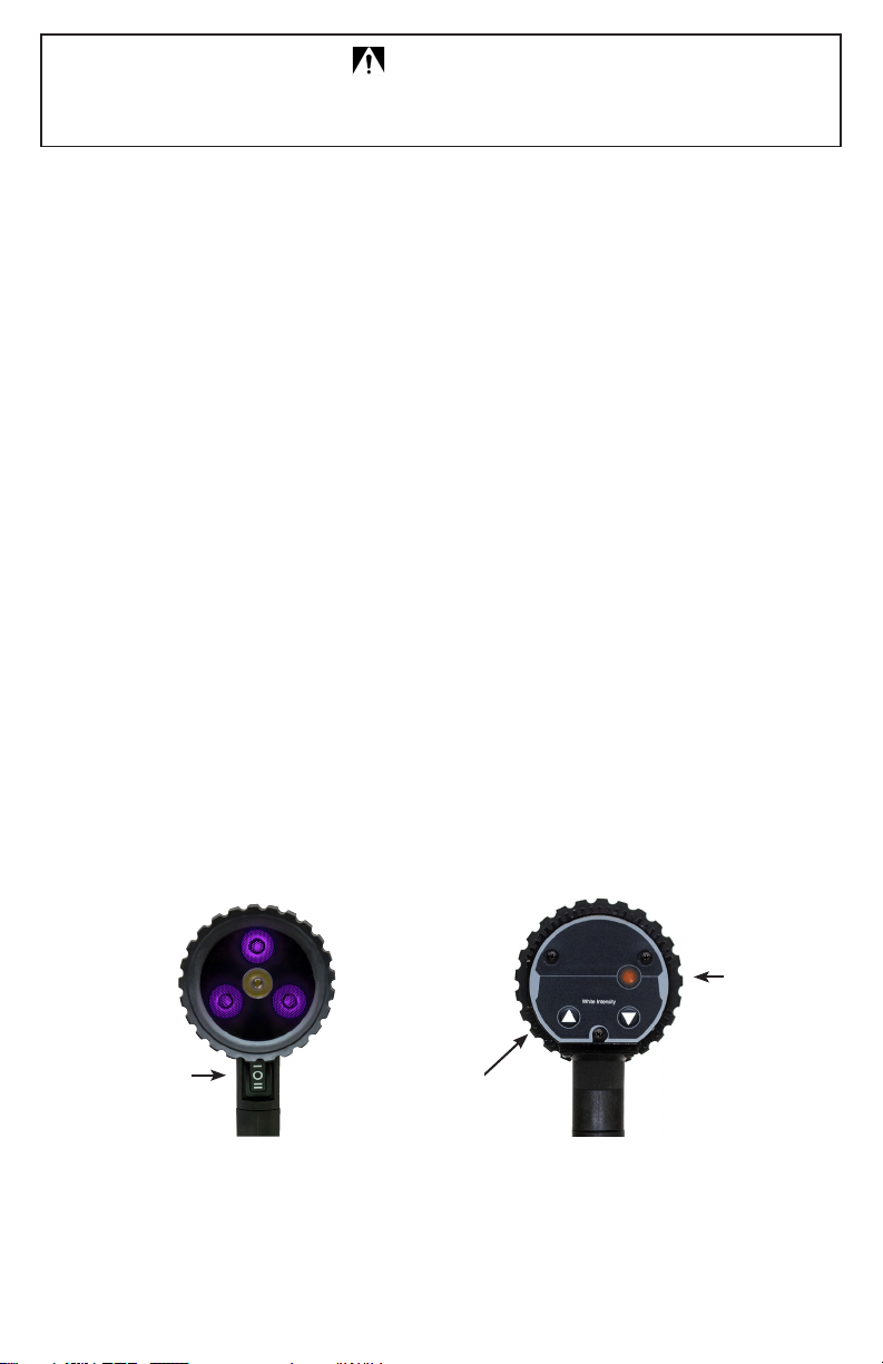
• Intens2
•
minimale de 1 200µW/cm2(ASTM E3022-15 / Rolls Royce RRES 90061).
• 2)
• Lentilles UV-A de longue durée.
• Conception sans dégagement de chaleur et sans ventilateur.
• Poids léger et conception robuste.
•
•
•
• Rapport de validation (Rolls Royce RRES 90061) inclus.
CARACTÉRISTIQUES TECHNIQUES
Série uVision™
UV-365SBLCR
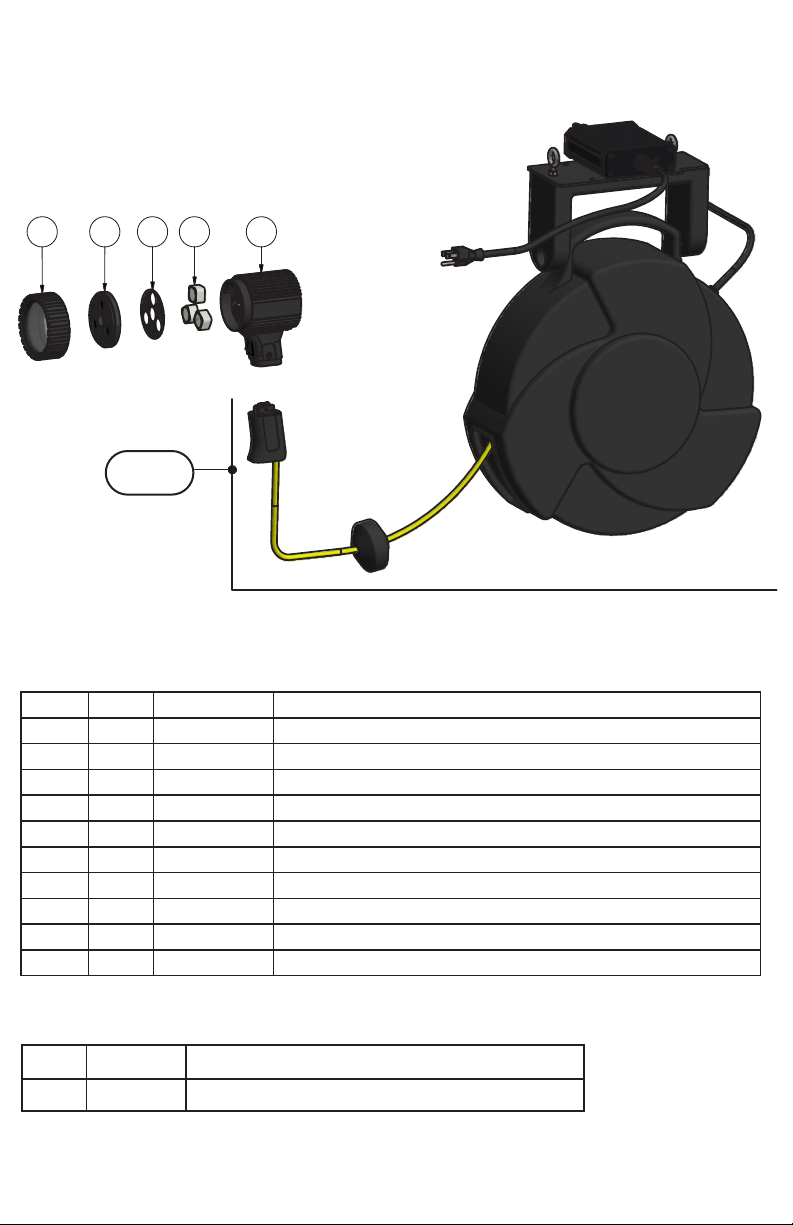
Poids 880g (1,94lb) sans alimentation.
SPÉCIFICATIONS ÉLECTRIQUES
SPÉCIFICATIONS DES CORDONS D’ALIMENTATION
NUMÉRO DE RÉFÉRENCE DE LAMPE
Caractéristiques techniques d’UV-365SBLCR
MESURE DE L’INTENSITÉ DE LA LAMPE
Spectro-UV. Composez le numéro gratuit 1-866-230-7305.

11
VUE ÉCLATÉE DE L’UV-365SBLCR
ET PIÈCES DE RECHANGE
1
1
2
2
3
3
4
4
A A
B B
WESTBURY, NEW YORK 11590
956 BRUSH HOLLOW ROAD
CORPORATION
SPECTRONICS
REV
DRAWING NUMBER
SIZE
DATE
DATE
DATE
APPROVED
CHECKED
DRAWN
TITLE
NEXT ASSY.
NO. REQ'D
SCALE
30'
.005
ANG.DEC.
UNLESS OTHERWISE SPECIFIED
DIMENSIONAL TOLERANCES
FRAC.
1/64
+
- -
+-
+
FILE NAME & PATH
PROPERTY OF SPECTRONICS CORP; DO NOT DUPLICATE
MATERIAL FINISH SPECTRONICS PART NO.
1
A-18103
B
PHILIPC
11/8/2017
UV-365HCR
MANUAL
C:\Engineering\Projects\TRITAN\Ultravision 365\A-18103, UV-365HCR, ASSEMBLY, MANUAL.idw
UV-365HCR
BP 2 3 4 5
UV-365HCR REPLACEABLE PARTS LIST
ITEM QTY PART NO. DESCRIPTION
1A 1 130405 POWER SUPPLY, REEL, 50FT, UVISION, 120V, US
1B 1 130406 POWER SUPPLY, REEL, 50FT, UVISION, 230V, EU
1C 1 130407 POWER SUPPLY, REEL, 50FT, UVISION, 240V, AU
1D 1 130408 POWER SUPPLY, REEL, 50FT, UVISION, 230V, UK
BP 1FP-600 FILTER PROTECTOR ASSEMBLY
2 1 128196 FRONT COVER PLATE/ FILTER ASSEMBLY
3 1 128385 FRONT COVER GASKET
4 3 129427 UV LED LENS, WITH ADHESIVE
5 1 130336 LAMP HOUSING ASSEMBLY
1A
1B
1C
1D
QTÉ PIÈCE Nº DESCRIPTION
1 UVS-30
Accessoires
QTÉ PIÈCE Nº
1A 1 130405 ALIMENTATION, ENROULEUR, 15,2 M (50 '), UVISION, 120 V, US
1 130406 ALIMENTATION, ENROULEUR, 15,2 M (50 '), UVISION, 230 V, EU
1C 1 130407 ALIMENTATION, ENROULEUR, 15,2 M (50 '), UVISION, 240 V, AU
1D 1 130408 ALIMENTATION, ENROULEUR, 15,2 M (50 '), UVISION, 230 V, UK
1E 1 130504
1 FP-600
2 1 128196
3 1 128385
4 3 UL-110 LENTILLES À LED UV, AVEC ADHÉSIF
5 1 130336
Pièces de rechange
1A-1E

12
CONSIGNES RELATIVES À L’ENROULEUR DE CÂBLE
INSTALLATION
Assurez-vous que le dispositif est correctement équilibré.
FONCTIONNEMENT
sur la lampe.
l’enrouleur.
MAINTENANCE
Pour ce faire, n’utilisez pas de solvants tels que l’essence ou la térébenthine.
INFORMATIONS GÉNÉRALES RELATIVES À LA SÉCURITÉ
• Débranchez le dispositif chaque fois que vous devez le nettoyer ou l’inspecter.
SÉCURITÉ DE LA ZONE DE TRAVAIL
involontaire.
MISE À LA TERRE
les normes et ordonnances au niveau local. LA PRISE FOURNIE NE PEUT ÊTRE MODIFIÉE. Si elle
chargée de l’entretien.

13
7/20 AM18031ML-4
IMPRESO EN EE. UU.
Serie uVision™
Lámpara LED de UV-A/luz blanca para
inspección no destructiva (NDT)
N.° de parte UV-365SBLCR
www.Spectro-UV.com
4 Dubon Ct., Farmingdale, NY 11735
866-230-7305
ENG - 1 FR - 7 ES - 13 DE - 19

14
PELIGRO
Este producto emite radiación ultravioleta. Evite estar expuesto a ella.
PARA USO PROFESIONAL SOLAMENTE
INSTRUCCIONES DE SEGURIDAD IMPORTANTES (Lea todas las instrucciones)
• No use la Serie uVision™ Lámpara LED de UV-A/luz blanca para inspección no destructiva
(NDT) (UV-365SBLCR) si está dañada o si tiene el cable dañado.
• No vea la luz directamente. Use SIEMPRE los lentes protectores que absorben los rayos UV
cuando utilice la lámpara. Utilícela con poca iluminación de ambiente para lograr los mejores
resultados de inspección. Entre más oscuro sea el lugar, mayor será el brillo fluorescente.
• La uVision™ no está aprobada para utilizarse en atmósferas peligrosas. No intente usarla en
áreas que requieran iluminación a prueba de explosiones.
• Nunca utilice este equipo de alguna manera que no se especifique en estas instrucciones
porque puede poner en peligro su seguridad.
• NUNCA apunte la lámpara en dirección a otro ser humano. ¡SOLO se debe utilizar para
inspecciones fluorescentes profesionales!
• NO intente modificar el ensamblaje de los lentes o la salida de la luz. Si lo hace, puede alterar el
desempeño o la intensidad de la uVision™ y no cumplirá con los requisitos.
OPERACIÓN
• Las lámparas UV-A de inspección de la serie uVision™ están equipadas con un cable de
alimentación de uso pesado.
• La lámpara se envía con el cable correcto instalado para el país de destino.
• Conecte el enchufe a una fuente de energía que cumpla con los requisitos de electricidad que se
• La lámpara tiene un interruptor basculante de energía de tres posiciones (II - UV; O - apagado;
I - luz blanca) en el mango.
•
placa trasera de la lámpara.
•
fuera de las normas de cumplimiento con las REES. Para encender de nuevo la unidad después
de haberse apagado, apáguela y préndala con el interruptor basculante de tres posiciones.
• ADVERTENCIA: Asegúrese de usar piezas de reemplazo uVision™ originales. Si usa partes de
Interruptor
basculante
Indicador de
la poder
Ajuste de
intensidad de la
luz blanca
CAMBIO DEL CABLE DE ALIMENTACIÓN DE LA LÁMPARA
Se instalará en la lámpara el cable correcto para el país de destino cuando se haga el pedido. El cable
de alimentación se integra en la parte más baja del mango de la lámpara, formando un ensamblaje
del cable/la lámpara. Con las piezas de reemplazo viene un conjunto de instrucciones detalladas para
cambiar el cable de la lámpara. Póngase en contacto con el Departamento de Servicio al Cliente para
obtener más detalles. Llame sin costo al 1-866-230-7305.

15
DESENSAMBLAJE DEL PROTECTOR DEL FILTRO PARA MANTENIMIENTO
®®(FP-600), primero quite el soporte
delantera de la lámpara.
®®de vidrio,
®en el soporte de goma de la cubierta/el
REEMPLAZO DE LOS LENTES UV
Los lentes UV-A (UL-110) que cubren los tres LED UV-A se deben reemplazar con el tiempo. Se
solarizarán (se verá borroso y se pondrán amarillos) con el uso recurrente. Viene un conjunto de
instrucciones detalladas con los lentes UV-A de reemplazo (UL-110). Consulte la sección Piezas de
reemplazo y póngase en contacto con Servicio al cliente para obtener más detalles
CONDICIONES AMBIENTALES
•
baja presión);
•
•
GARANTÍA LIMITADA
contacto con el Departamento de Servicio al Cliente de Spectro-UV. Proporcione el modelo, el número
de serie de la unidad y la fecha de compra. La información de serialización de la unidad se ubica (1) en
el paquete donde se envía la unidad, (2) grabado en el mango de la unidad y (3) etiquetado al reverso
de la placa trasera de la unidad.
ESTADO DEL INDICADOR LED DE LA BATERÍA
Apaga

16
CARACTERÍSTICAS CLAVE
•
•
UV-A de 1,200µW/cm2(ASTM E3022-15/Rolls Royce RRES 90061).
• 2)
• Lentes UV-A de larga duración.
•
• Construcción ligera y resistente.
• Luz LED blanca para inspección.
•
de polvo y de chorros de agua de baja presión (desde cualquier dirección). Para obtener más
•
• Informe de validación (Rolls Royce RRES 90061) incluido.
ESPECIFICACIONES TÉCNICAS
Serie uVision™
UV-365SBLCR UV-A (365nm) y luz blanca
Peso 880g (1.94lb) sin suministro de energía.
Fuente de luz 3 LED UV-A, 1 LED de luz blanca
ESPECIFICACIONES ELÉCTRICAS
ESPECIFICACIONES DEL CABLE DE ALIMENTACIÓN
NÚMERO DE PARTE DE LA LÁMPARA
Detalles técnicos de la UV-365SBLCR
MEDICIÓN DE INTENSIDAD DE LA LÁMPARA
Debe revisar la lámpara de la serie uVision™ de forma regular para asegurarse de que está
funcionando a la intensidad UV requerida. Spectro-UV ofrece una variedad de sensores y medidores.
y VIS de longitud de onda dual para medir la irradiación de una fuente de luz forma precisa. También
unidades, póngase en contacto con el Departamento de Servicio al Cliente de Spectro-UV. Llame sin
costo al 1-866-230-7305.

17
1
1
2
2
3
3
4
4
A A
B B
WESTBURY, NEW YORK 11590
956 BRUSH HOLLOW ROAD
CORPORATION
SPECTRONICS
REV
DRAWING NUMBER
SIZE
DATE
DATE
DATE
APPROVED
CHECKED
DRAWN
TITLE
NEXT ASSY.
NO. REQ'D
SCALE
30'
.005
ANG.DEC.
UNLESS OTHERWISE SPECIFIED
DIMENSIONAL TOLERANCES
FRAC.
1/64
+
- -
+-
+
FILE NAME & PATH
PROPERTY OF SPECTRONICS CORP; DO NOT DUPLICATE
MATERIAL FINISH SPECTRONICS PART NO.
1
A-18103
B
PHILIPC
11/8/2017
UV-365HCR
MANUAL
C:\Engineering\Projects\TRITAN\Ultravision 365\A-18103, UV-365HCR, ASSEMBLY, MANUAL.idw
UV-365HCR
BP 2 3 4 5
UV-365HCR REPLACEABLE PARTS LIST
ITEM QTY PART NO. DESCRIPTION
1A 1 130405 POWER SUPPLY, REEL, 50FT, UVISION, 120V, US
1B 1 130406 POWER SUPPLY, REEL, 50FT, UVISION, 230V, EU
1C 1 130407 POWER SUPPLY, REEL, 50FT, UVISION, 240V, AU
1D 1 130408 POWER SUPPLY, REEL, 50FT, UVISION, 230V, UK
BP 1FP-600 FILTER PROTECTOR ASSEMBLY
2 1 128196 FRONT COVER PLATE/ FILTER ASSEMBLY
3 1 128385 FRONT COVER GASKET
4 3 129427 UV LED LENS, WITH ADHESIVE
5 1 130336 LAMP HOUSING ASSEMBLY
1A
1B
1C
1D
CANTIDAD NO. DE PARTE DESCRIPCIÓN
1 UVS-30
Accesorios
CANTIDAD NO. DE PARTE DESCRIPCIÓN
1A 1 130405
1 130406
1C 1 130407
1D 1 130408
1E 1 130504
1 FP-600
2 1 128196
3 1 128385
4 3 UL-110 LENTES LED UV CON ADHESIVO
5 1 130336
Piezas de reemplazo
VISTA AMPLIADA DE LA UV-365SBLCR
Y PIEZAS DE REEMPLAZO
1A-1E

18
INSTRUCCIONES DE LA BOBINA DE CABLE
INSTALACIÓN
Modelos de lámparas tipo balastra (montaje en el techo)
• Seleccione un lugar cerca de una toma de corriente.
• Cuelgue el ensamblaje de la lámpara de un montaje en el techo adecuado. Conecte una cadena al
montaje en el techo. Después, sujete la cadena a las armellas que están en la parte superior de la
unidad. Asegúrese de que la unidad esté equilibrada.
OPERACIÓN
• Conecte el cable principal a un enchufe que cumpla con los requisitos eléctricos que se mencionan
en la lámpara.
falla en el resorte de retracción.
• No deje que el cable se regrese a la bobina de modo incontrolado.
MANTENIMIENTO
humedecido. No use solventes como gasolina, aguarrás, etc. para limpiar la unidad.
INFORMACIÓN GENERAL DE SEGURIDAD
receptáculos de 3 polos que acepten el enchufe de la unidad.
• Desconecte la unidad de la fuente de alimentación antes de dar servicio o inspeccionarla por algún
motivo.
SEGURIDAD DEL ÁREA DE TRABAJO
Mantenga el área de trabajo limpia, seca, ordenada y bien iluminada. Las áreas de trabajo desordenadas,
lo puede acercar de manera peligrosa a otras herramientas de corte y piezas giratorias. Tenga cuidado
con todos los cables eléctricos, circuitos eléctricos, tuberías de agua y otros peligros mecánicos cerca
CONEXIÓN A TIERRA
Esta bobina debe estar conectada a tierra para proteger al operador de una descarga eléctrica. El
de acuerdo con TODOS los códigos y las normas locales. NO MODIFIQUE EL ENCHUFE INCLUIDO.
Si el receptáculo no es compatible, pida a un eléctrico profesional que instale un receptáculo adecuado.
INFÓRMESE con un eléctrico profesional o una persona de servicio si no comprende totalmente las

19
7/20 AM18031ML-4
uVision™-Serie
UV-A/Weißlicht-LED-NDT-Inspektionslampe
Teile-Nr. UV-365SBLCR
www.Spectro-UV.com
4 Dubon Ct., Farmingdale, NY 11735
866-230-7305
ENG - 1 FR - 7 ES - 13 DE - 19

20
ACHTUNG
Dieses Produkt gibt ultraviolette Strahlung ab.Vermeiden Sie es, sich dieser auszusetzen.
NUR ZUM EINSATZ BEI ÜBERPRÜFUNGEN DURCH EINEN FACHMANN.
WICHTIGE SICHERHEITSHINWEISE (Lesen Sie alle Hinweise)
• Benutzen Sie die uVision™-Serie UV-A/Weißlicht-LED-NDT-Inspektionslampe (UV-365SBLCR)
nicht, wenn die Lampe oder das Kabel beschädigt ist.
• Schauen Sie nicht direkt in das Licht. Tragen Sie beim Betrieb der Lampe IMMER die mitgelieferte
UV-Schutzbrille. Am besten verwenden Sie die Lampe in abgedunkelter Umgebung. Je dunkler der
Raum, umso größer der Fluoreszenzkontrast.
• Die uVision™ ist nicht zur Nutzung in explosionsgefährdeter Atmosphäre zugelassen. Versuchen
Sie nicht, sie in Bereichen einzusetzen, die explosionsgeschützte Beleuchtung erfordern.
• Benutzen Sie dieses Gerät niemals anders als ain dieser Anleitung beschrieben, da dies Ihre
Sicherheit gefährden könnte.
• Richten Sie die Inspektionslampe NIEMALS auf einen anderen Menschen. Sie ist
AUSSCHLIESSLICH für professionelle Fluoreszenzinspektionen vorgesehen!
• Versuchen Sie NICHT, die Linsenkonstruktion oder den Lichtausgang zu verändern. Dies könnte
zu einer veränderten Leistung und Intensität deruVision™ sowie zu einem nicht konformen Betrieb
führen.
BETRIEB
• Die UV-A-Inspektionslampen der uVision™-Serie sind mit einem verstärkten Stromkabel
ausgestattet.
•
• Verbinden Sie den Stecker mit einer Stromquelle, die den auf dem Etikett angegebenen
elektrischen Anforderungen entspricht.
•
•
•
• WARNUNG: Achten Sie auf die Verwendung von uVision™-Originalersatzteilen. Die Verwendung
von Ersatzteilen anderer Hersteller könnte die Leistung des Produkts beeinträchtigen und führt
Kippschalter
Kontrollleuchte
Einstellung,
AUSTAUSCH DES LAMPEN-STROMKABELS
der Ersatzteile enthalten. Für weitere Informationen kontaktieren Sie bitte den Kundendienst. Rufen
Sie die kostenlose Nummer 1-866-230-7305 an.
Other manuals for uVision Series
3
This manual suits for next models
1
Table of contents
Languages:
Other Spectroline Lighting Equipment manuals

Spectroline
Spectroline NANO 365 Series User manual

Spectroline
Spectroline BIB-150P/F/J Series User manual

Spectroline
Spectroline NANO 365 Series User manual

Spectroline
Spectroline uVision Series User manual

Spectroline
Spectroline QUADRAN 365 AC Series User manual

Spectroline
Spectroline uVision Series User manual

Spectroline
Spectroline NANO 365 Series User manual

Spectroline
Spectroline TRITAN 365 AC Series User manual

Spectroline
Spectroline EDGE 13 User manual

Spectroline
Spectroline EDGE 13 User manual