SPX POWER TEAM C12-TON Use and care manual

C12-TON HAND HYDRAULIC
COMPRESSION TOOL
Form No. 1000026
C12-TON-B
Operating Instructions and
Parts List for:
Tech. Services: (800) 477-8326
Fax: (800) 765-8326
Order Entry: (800) 541-1418
Fax: (800) 288-7031
SPX Corporation
5885 11th Street
Rockford, IL 61109-3699 USA
Internet Address:
http://www.powerteam.com
®
INTRODUCTION
The C12-ton compression tool was designed for installing tubular
compression accessories on stranded electrical conductors. Twelve tons
thrust can be developed by this hand-operated compressor.
The compressor piston can be adjusted to a position that will require a
minimum of hand pumping to compress an accessory.
Twisting the pump handle clockwise will advance the piston until the
lower die-half contacts the accessory to be compressed. Compression is
completed by pumping the pump lever. When the die-halves touch the
compression is complete.
The piston is retracted by pulling the trigger on the pump lever and
making another pumping stroke. It will retract only to the positions
previously set, thus minimizing the amount of pumping needed to
complete the next compression.
Note that all operating controls are located such that the operator need
not remove his hands from the tool.
THE C12-TON TOOL IS NOT TO BE USED FOR "HOT LINE" WORK.
SPECIFICATIONS
PUMP SECTION:
SINGLE SPEED WITH MECHANICAL RAPID ADVANCE,
PUMP OUTPUT .042 CU.IN. (.00069 LITER) PER STROKE.
HIGH PRESSURE RELIEF VALVE SET TO OPEN AT 10,400/10,000 PSI (716/689 BAR).
RESERVOIR CAPACITY, 4 7/8 CU.IN. (.08 LITER).
USABLE OlL, 3 3/4 CU.IN. (.06 LITER)
OIL TYPE USED, AMOCO RYKON MV.
HANDLE EFFORT, 4 1/8 LBS. (1.87 KG) PER 1000 PSI (68.9 BAR)
TOOL SECTION:
1.813 (4.605 CM) DIA.RAM, .912 (2.31 CM) STROKE WITH DIES.
REQUIRES 2.35 CU.IN. (.038 LITER) OIL MINIMUM.
CRIMPING FORCE, 26,332 LBS. (11,944 KG)
AT 10,200 PSI (702 BAR)
(13.1 TONS U.S., 11.89 TONS METRIC)
TOTAL WEIGHT, 13.6 LBS. (6.16 KG).
CRIMPING CAPACITY:
NO.6 THRU 750MCM CU, 500MCM AL.
(3 THRU 379.5 SQ.MM.CU, 253 SQ.MM.AL)
Sheet No. 1 of 6
Rev Date: 09 Feb 2004
Litho in USA
WARNING
Operating Instructions and Parts List, Form No. 1000026, Back sheet 1 of 6
IMPORTANT SAFETY INFORMATION
It is the operators responsibility to read and
understand the following safety statements,
• Only qualified operators should install, operate,
adjust, maintain, clean, repair, or transport this
machinery.
• Inspect tool before use. Replace any worn or
damaged parts. Failure to observe these warnings
can result in severe injury or death.
Keep hands away from the crimping tool head
when crimping.
WARNING
To help prevent personal injury,
• Always wear eye protection whenever
operating hydraulic equipment.
• Always wear hearing protection as
required.
• Operation, repair, or maintenance of hydraulic
equipment should be performed by a qualified
person who understands the proper function of
hydraulic equipment per local directives and
standards.
• Hydraulic equipment must be assembled correctly
and then checked for proper function before use. Use
hydraulic components of the same hydraulic
pressure ratings. An appropriate hydraulic pressure
gauge is recommended to monitor pressure.
• Never place your hands or other body
parts near a hydraulic fluid leak.
Never use your hands or other body parts
to check for a possible leak.
High pressure fluid can be injected under your skin
causing serious injury and/or infection.
• Exercise caution to avoid the risk of fire.
An incomplete crimp can cause a fire. Use
proper die, connector and cable. Improper
combinations can result in an incomplete
crimp.
• This tool is not insulated. When using this
unit near energized electrical lines, use
proper personal protective equipment.
• This tool is intended for two-handed operation.
Maintain a firm grip on both handles during
operation. Using this tool in any other manner can
result in injury or equipment damage.
• Properly dispose of all fluids, components, and
assemblies at the end of their useful life.
• Hydraulic fluid should be compatible with all
hydraulic components.
WARNING
IMPORTANT
WARNING
WARNING
This is the safety alert symbol.
It is used to alert you to potential personal injury
hazards. Obey all safety messages that follow this
symbol to avoid possible injury or death
Denotes an imminently hazardous situation which, if
not avoided, will result in death or serious injury.
Denotes a potentially hazardous situation which, if not
avoided, could result in death or serious injury.
Denotes a potentially hazardous situation which, if not
avoided, may result in minor or moderate injury.
Caution used without the safety alert symbol indicates
a potentially hazardous situation which, if not avoided,
may result in property damage.
Denotes an operating or service procedure or condition
considered essential for expedient and efficient
operation and service.
IMPORTANT
CAUTION
CAUTION
WARNING
DANGER

Operating Instructions and Parts List, Form No. 1000026
OPERATING INSTRUCTIONS
DO NOT OPERATE THE COMPRESSOR WITHOUT DIES.
Select the proper dies for use on the accessory to be compressed. Push the die release button on the C-head and
slide one of the identical die-halves into position. The die retainer pin locks the die in place. Insert the other die- half
in the ram body by depressing the die release button located in a slight well in the ram.
Place the compressor in position over the accessory to be compressed. If the accessory is larger in diameter than the
throat opening of the C-head, put the compressor over the conductor and then slide it over the accessory in the
correct position for the first compression. Twist the reservoir handle clockwise until the lower die-half advances to
touch the accessory to be compressed. Back off a quarter turn - do not turn the reservoir handle again - ram will
retract to this preset position each time the hydraulic pressure is released. This partial retraction of the ram allows
enough clearance to move the compressor along the accessory for each successive compression and requires a
minimum of hand pumping for the next compression.
Complete each compression by pumping until the dies touch at their flat surfaces nearest the throat of the C-head. If
it is not convenient to observe the dies, pump until the safety valve operates, although compression will have been
completed before the safety valve relieves the hydraulic pressure. The operation of the valve will cause an audible
click and a pronounced difference in the feel of the pumping.
To retract the ram, open the compressor handles, hold the pressure release trigger down, and close the handles
firmly to push in the pressure release plunger. The ram will retract to the pre-selected position. If the die opening must
be increased further, use same procedure as above and while the trigger is held down, turn the reservoir handle
counter clockwise.
It should be noted that the ram can be advanced rapidly by merely twisting the reservoir handle, but it is necessary to
both trip the release trigger and twist the reservoir handle to retract the ram from a pre-selected position.
Move the compressor into position for the next compression and repeat the procedure. Do not use the compressor for
any purpose other than that for which it was designed. This tool has been manufactured to precision tolerances. It
should be used with the same care and attention as any other fine piece of equipment.
The C-head of the compressor can be rotated through 180 degrees to place the throat opening perpendicular to the
conductor even though the operator may be working from an awkward position on a utility pole.
THE NEOPRENE COVER IS NOT INTENDED TO AFFORD PROTECTION TO THE
OPERATOR FOR “HOTLINE” WORK.
Compatible Hydraulic Fluids:
The use of Amoco Rykon MV oil is recommended. Compatible fluids include:
Mobil DTE 13
Mobil ATF 220
Shell Tellus 32
Arco Dexron III
Citgo AW32
Citgo Dexron III
Other fluids also may be used if they meet or exceed the following specifications:
Viscosity: 180 SSU at 100 degree F.
Flash Point: 350 degree F
Pour Point: -50 degree F
WARNING
WARNING
Sheet No. 2 of 6
Rev Date: 09 Feb 2004

Operating Instructions and Parts List, Form No. 1000026, Back sheet 2 of 6
SERVICING INSTRUCTIONS
PREVENTIVE MAINTENANCE
The majority of service troubles are caused by dirt collecting about the tool or in the oil system. Keep the tool clean
and prevent foreign matter from entering the compressor while filling the reservoir. Lubricate all moving parts and
keep the C-head stop screw, ram guide screw, and reservoir handle stop screw tightened.
FILLING RESERVOIR
To add or replace oil in the compressor, retract the ram completely. Loosen the reservoir handle stop screw and
remove the handle. Remove the reservoir plug and O-ring seal. Pull the stem of the reservoir piston out as far as
possible. Add oil until it fills the stem. See “Compatible Hydraulic Fluids” Section.
DO NOT USE BRAKE FLUID OF ANY KIND.
Before replacing the reservoir plug, advance the ram a short distance by stroking the pump lever. Retract the ram by
pulling the trigger on the pump lever and make a pumping stroke, first having taken precautions against splashing of
the oil. Repeat this procedure until air bubbles cease appearing. Add oil if necessary to fill the stem, first making
certain the C-head ram is fully retracted so that too much oil is not added. Replace the O-ring, reservoir magnetic
plug and handle; tighten the reservoir handle stop screw.
Pump until the die faces meet, and then retract the ram. If the ram does not retract completely, too much oil had been
added. Drain enough to permit complete retraction.
REPLACING HYDRAULIC SEALS
Maintenance and repair of this tool should be provided with the same reasonable care given other fine equipment.
Service should be performed by adequately trained personnel in repair shops under clean conditions. For those
owners having adequately staffed repair facilities, a hydraulic seal replacement kit No. 3-3554 containing O-rings,
gaskets, etc., needed for one complete replacement of hydraulic seals in the compressor. Include compressor serial
number when ordering all parts.
To replace the seals it is necessary to separate the C-head and piston assemblies from the cylinder. Remove both
die halves. Removing the quick coupler drains the oil and aids in dis-assembly. Remove screw and washer to unlock
cylinder.
Unscrew the C-head and the piston will also rotate. After nine complete turns the piston spring rod is unthreaded
from within the cylinder and the piston guide arrangement should be removed. Further rotation will separate the C-
head from the cylinder. Pull the piston from the cylinder. All seals and rings are now accessible.
Reassemble with clean parts lubricated with the same grade of oil used in the remote pump. The steel piston washer
and leather wiper are installed on the outside of the piston with the steel washer next to the shoulder on the piston.
Insert piston into cylinder, rotate assembly until hand tight. Backoff one-half turn to permit the piston wipers to center
themselves in the C-head bore. Thread the C-head onto the cylinder until the bottom of the die groove in piston is
flush at a corresponding point on the C-head. Continue rotation until the key slots align. At this attitude, top of piston
should not have entered C-head opening and a die-half can be inserted in piston groove.
Reassemble the piston guide arrangement with Loctite on screw threads.
Invert the tool and fill the cylinder with oil. Bleed air from cylinder by rocking tool back and forth. Assemble 3/8 inch
female quick coupler.
WARNING

Operating Instructions and Parts List Form No. 1000026
TROUBLE SHOOTING
Sheet No. 3 of 6
Rev Date: 09 Feb 2004
If the ram will not extend completely, it will generally be found that there is an insufficient amount of oil in the
compressor's hydraulic system. This trouble can also be caused by faulty pump plunger packing or release valve
packing by the pressure release valve being stuck open, or by foreign matter preventing the release valve balls from
seating properly. Faulty packing will usually be detected by excess oil leakage around the pump plunger. A stuck
valve ball can usually be freed by rapping the tool sharply.
Avoid damage to other parts in the process of rapping. Foreign matter can frequently
be flushed from a valve seat by pumping very rapidly with abrupt strokes.
If the dies will not close and pumping is difficult, check the die number to make certain the proper size die is being
used on the accessory. If the dies will not close and pumping becomes easier, usually additional oil is needed in the
compressor. There is also the possibility that the pressure release valve balls are not seating properly.
If the ram will not retract completely, it will generally be found that there is too much oil in the compressor. Drain
enough to permit complete retraction. If the ram will not retract and the oil reservoir is not full, the ram is likely being
held by a deformed washer.
A small amount of leakage is desirable around the ram; pump plunger, and pressure release valve plunger to
lubricate these parts. If enough leakage occurs to cause the oil to run, the packing should be replaced.
If rotating the reservoir handle will not advance the ram to within a half-inch of closing the dies, additional oil is
needed in the compressor. If rotating the handle will not move the ram, either the ram is being held by a deformed
washer or the reservoir piston has been deformed and is seizing on the reservoir walls. Such deformation occurs only
if the reservoir handle is screwed tight against a fully advanced ram and the pressure release or safety valve is
operated. The momentary pressure surge against the face of the reservoir piston may cause it to buckle and wedge
against the wall of the reservoir. No purpose is served in screwing the handle tight and doing so abuses the tool.
If the dies do not lock in position, the action of the retaining pins is probably restricted by dirt. Clean and oil these
parts.
If it is difficult to unlock the die-haves, the die release buttons should be lubricated. The die retaining pin set screw in
the C-head above the die release button is staked in position. To further tighten this screw will make it difficult or
impossible to release the die.
CAUTION
6
4
7
3
5
8
2
1
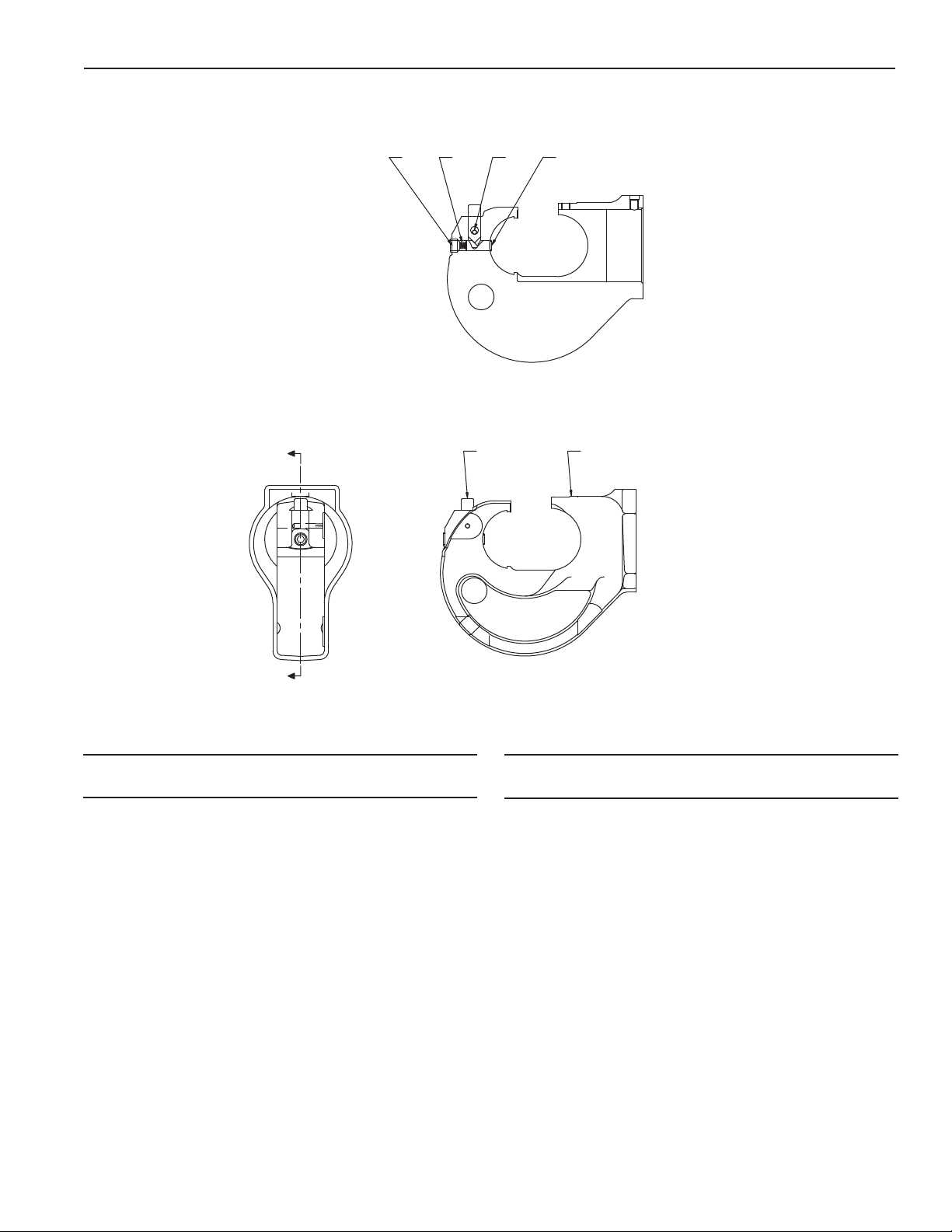
1. Top Die Release Button
2. Bottom Die Release Button
3. Piston Guide Screw
4. Piston
5. Reservoir
6. Reservoir Handle
7. Release Striker
8. Pump Lever
Illustration

Operating Instructions and Parts List, Form No. 1000026, Back sheet 3 of 6
PARTS LIST
11000056 1 Label, (Tradename Power Team)
21000055 1 Decal, (Warning & Caution)
3420691 1 Decal, (Product Blank)
45-0691 1 Ring, Tru-Arc #5103-31
53-1199 1 Pin, Fulcrum
63-1204 1Key
75-1258 1 Lockwasher 1/4 x .047 x .078 HI-C
83-1203 1 Screw, Key
93-1205 1 Washer, Piston
10 3-1211 1 Wiper
11 3-1192 1 Lever Assembly
12 5-0342 1 Screw. 8-32 x 1/8 Flat Pt. Skt. Se
13 3-1200 1 Screw, Stop
14 3-1196 1 Handle, Assembly
15 5-3667 1 Screw, 3/8-16 x 1/2 Fill. Hd. Mach.
16 10268 1 O-Ring, .50 x .37 Nitrile
17 3-1207 1 Rubber Covering, Cap
18 3-1197 1 Piston, Reservoir
19 3-5071 1 Rubber Covering, Cylinder
20 3-1201 1 Cap, Reservoir
21 5-1260 1 Quad-Ring, 1-5/8 x 1-7/8 x 1/8
22 3-1195 1 Cylinder Assembly
23 5-1263 1 O-Ring
24 5-1259 2 Screw, 10-24 x 1/4 SHCS
25 12356 2 Washer, Tooth Int. .37 x .20
26 3-1214 1 Ring, Back-up
27 3-1193 1 Ram Assembly
28 3000094 1 C-Head Assembly, ( Coated)
ITEM NOT SHOWN
2000147 1 Bag, Nylon Carrying
(2.5” x 6” x 22”)
Item Part No. Item Part No.
No. No. Req’d Description No. No. Req’d Description
27
28
22
11
14
18
513
20
8
6
9
17
10
26
23 19
16
15
12
47
24
25 21
2
KEEP HANDS AWAYFROM
CRIMPING TOOL HEAD
WHEN CRIMPING
CAUTION
DO NOT OPERATE
WITHOUT DIES - DO NOT
ADVANCERAM WITHOUT
WORK INSERTED
®
SPX Corporation, Rockford,IL 61109 USA
http://www.powerteam.com
Made in USA
1
3
C12-TON

Operating Instructions and Parts List Form No. 1000026
PARTS LIST
Sheet No. 4 of 6
Rev Date: 09 Feb 2004
SECTION A-A SECTION B-B
SECTION C-C
12
9
738
1
26
11 10
5
4
AA
B
B
C
C
13-1246 1Lever
23-1248 1 Striker, Release
33-1249 1 Shaft
43-1250 2 Bushing, Lever
53-1251 1 Pin, Plugger
63-1252 1 Spring, Striker
73-1253 1 Trigger
83-1254 1 Covering, Rubber, Lever
95-1265 1 Pin
10 5-1269 1 Pin
11 5-1270 1 Pin
12 5-1271 1 Pin
Item Part No. Item Part No.
No. No. Req’d Description No. No. Req’d Description
LEVER ASSEMBLY 3-1192
A
A
12
3456
SECTION A-A
13-1237 1 Shaft, Die Release
22000152 1 C-Head, Crimped
35-0662 1 Screw, Set
43-1239 1 Spring
55-1265 1 Pin, Driv-lok
63-1238 1 Pin, Die Retaining
Item Part No. Item Part No.
No. No. Req’d Description No. No. Req’d Description
Operating Instructions and Parts List, Form No. 1000026, Back sheet 4 of 6
PARTS LIST
C-HEAD ASSEMBLY 3000094

BB
CC
E
E
SECTION E-E
4
97
13
21
820
12
17
23
Apply 5-2538 adhesive to
threads of Item 10
SECTION A-A
6
10 14 19
14
SECTION B-B
SECTION C-C
16
2
Tighten Item 16 to 35 Ft.Lbs.
Stake Item 5 in place, Install
Item 3 flush to .030 above surface
and stake in place to prevent
Rotation
3
1
18
15
22
11
5
AA
13-0688 1 Spring, Compression
23-1215 1 Cylinder
33-1216 1 Screw, Valve Ball
43-1217 1 Screw, Release Stop
53-1218 1 Retainer, Screen
63-1219 1 Plunger, Pump
73-1220 1 Spacer, Packing
83-1221 1 Ring, Packing
93-1222 1 Plunger, Release
10 3-1223 1 Nut, Plunger
11 3-1225 1 Screen, Intake
12 3-1226 1 Spring, Compression
13 3-1227 1 Washer, Nylon
14 3-1228 2 Washer,
15 3-1229 1 Spring, Compression
16 3-2716 1 Valve Assembly, HP Relief
17 10377 1 Ball
18 10423 1 Ball
19 14763 1 O-Ring
20 10375 1 Ball
21 10268 1 O-Ring
22 10374 1 Ball
23 5-0658 1 Screw, Set
Item Part No. Item Part No.
No. No. Req’d Description No. No. Req’d Description
Operating Instructions and Parts List Form No. 1000026
PARTS LIST
Sheet No. 5 of 6
Rev Date: 09 Feb 2004
CYLINDER ASSEMBLY 3-1195
PTFE

263514
SECTION A-A A
A
13-0654 1 Plunger, Valve
23-1091 1 Screw, Adjusting
33-1232 1 Body, Valve
43-1233 1 Washer
53-1234 1 Spring
65-1264 1 Screw, Hollow Jam
Item Part No. Item Part No.
No. No. Req’d Description No. No. Req’d Description
98
5672
SECTION A-A
B
B
AA
SECTION B-B
3
4
1
10
Operating Instructions and Parts List, Form No. 1000026, Back sheet 5 of 6
PARTS LIST
H.P. RELIEF VALVE ASSEMBLY 3-2716
RAM ASSEMBLY 3-1193
13-1239 1 Spring
23-1240 1 Rod, Spring
33-1241 1 Pin, Retaining
43-1242 1 Shaft, Release
53-1243 1 Ram
63-1244 1 Spring
73-1245 1 Support, Spring
85-1266 1 Ring, Retaining
95-1267 1 Pin, Roll
10 5-1269 1 Pin, Roll
Item Part No. Item Part No.
No. No. Req’d Description No. No. Req’d Description

13-1255 1 Handle Sub-Assembly
(See below)
23-1256 1 Plug, Res. Handle
33-1257 1 Covering, Handle
Item Part No. Item Part No.
No. No. Req’d Description No. No. Req’d Description
13-4775 1 Handle, Reservoir 2 3-4776 1 Spacer, Stop
Item Part No. Item Part No.
No. No. Req’d Description No. No. Req’d Description
132
A
A
A
A
1
2Note: Use 5-2840 Adhesive to fasten spacer
in place. Spacer must not project above
O.D. Parts must be clean, dry, and free of
grease and oil prior to applying adhesive.
Operating Instructions and Parts List Form No. 1000026
PARTS LIST
Sheet No. 6 of 6
Rev Date: 09 Feb 2004
RESERVOIR HANDLE ASSEMBLY 3-1196
RESERVOIR SUB - ASSEMBLY 3-1255
Table of contents
Other SPX Tools manuals


