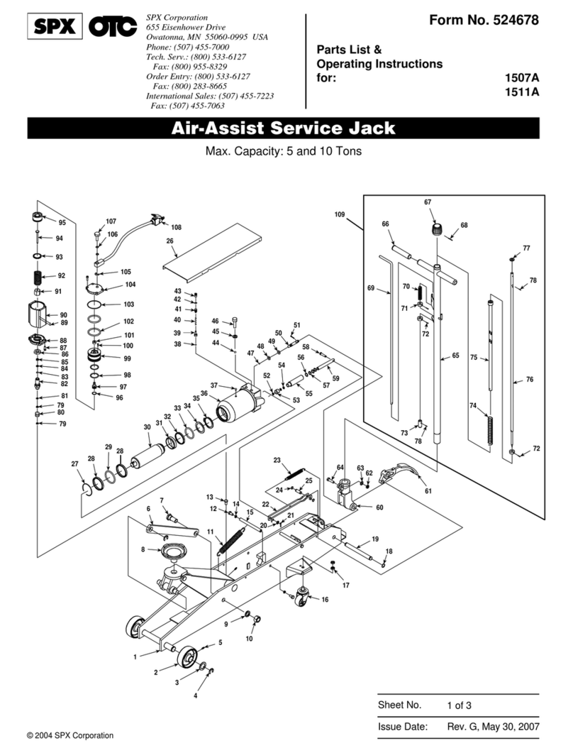
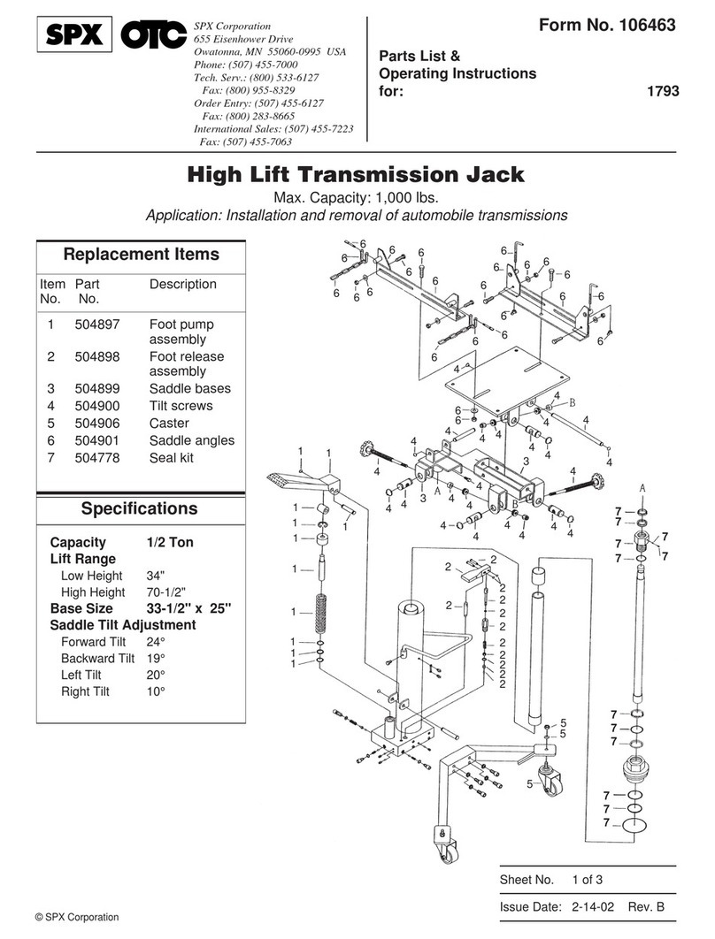
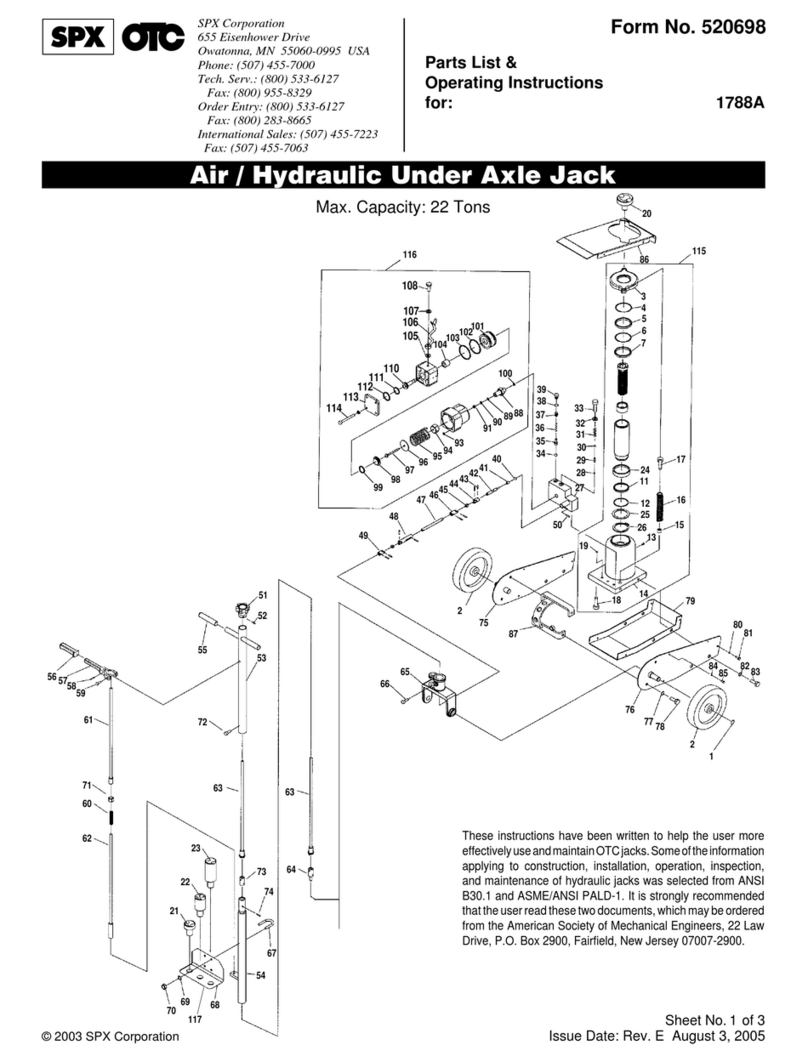
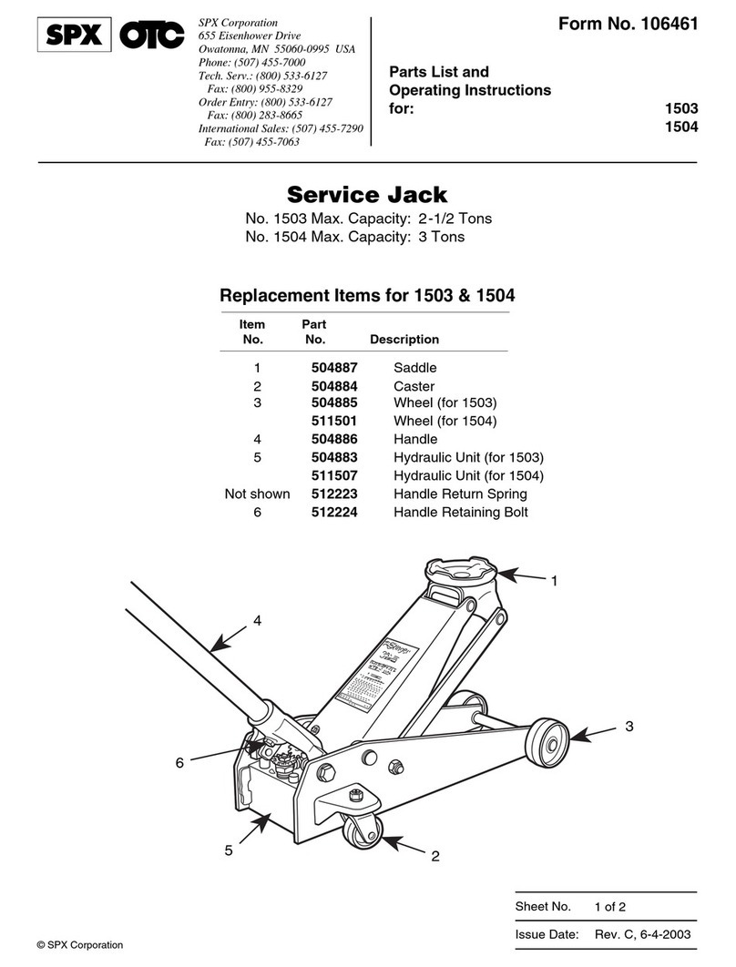
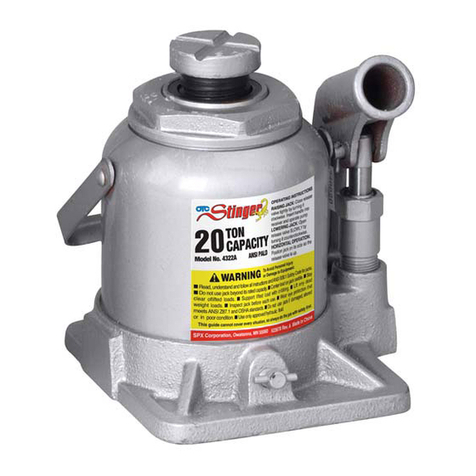
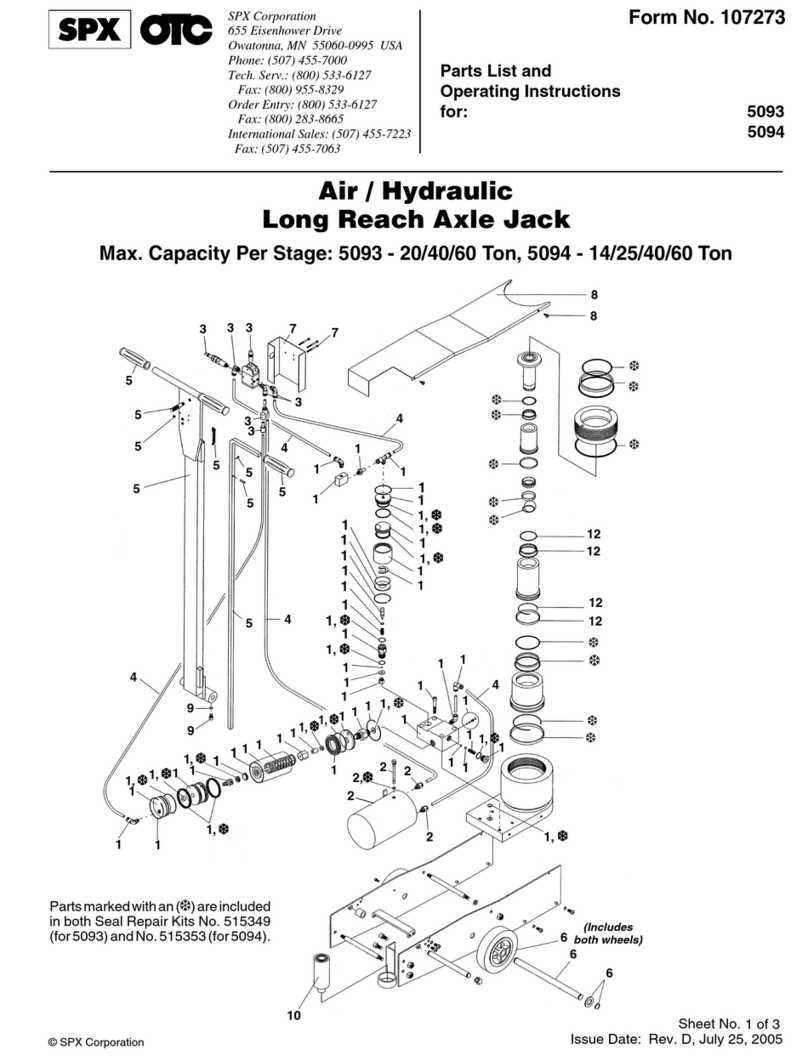
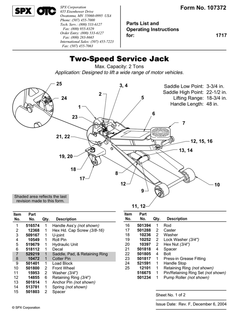
SPX 1505B User manual

© 2003 SPX Corporation
Sheet No.
Issue Date: Rev. C, 8-13-03
Parts List &
Operating Instructions
for: 1505B
1510B
Form No. 520770
Service Jack
Max. Capacity: 5 and 10 Tons
1 of 3
SPX Corporation
655 Eisenhower Drive
Owatonna, MN 55060-0995 USA
Phone: (507) 455-7000
Tech. Serv.: (800) 533-6127
Fax: (800) 955-8329
Order Entry: (800) 533-6127
Fax: (800) 283-8665
International Sales: (507) 455-7223
Fax: (507) 455-7063
2
3
4
5
9
10
16
17
18
19
8
6
7
11
12
13
14
15
22
23
21
24
25
26
27
28 29
30
32 33
34 35 36
38
39
40
41
42
43
44
45
46
47
48
49
50
51
5253
55
56
57
58
59
60
61
62
63
64
65
66
67
68
69
70
71
72
73
5
68
54
29
4
20
67

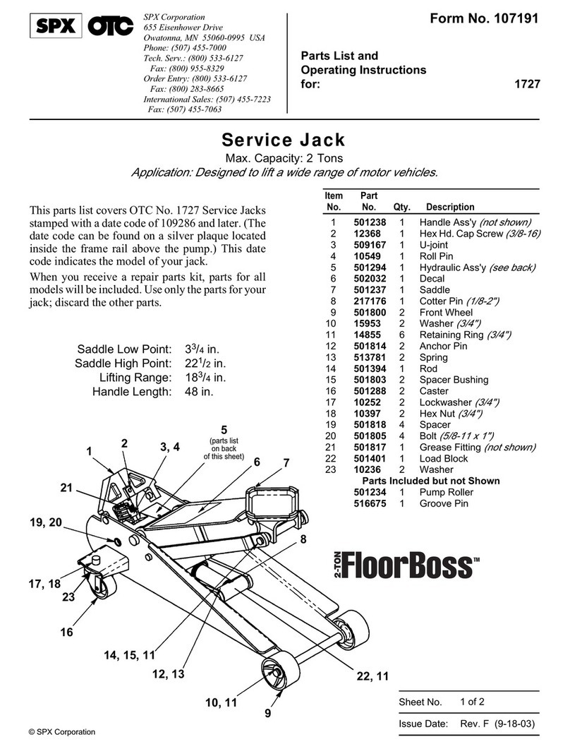
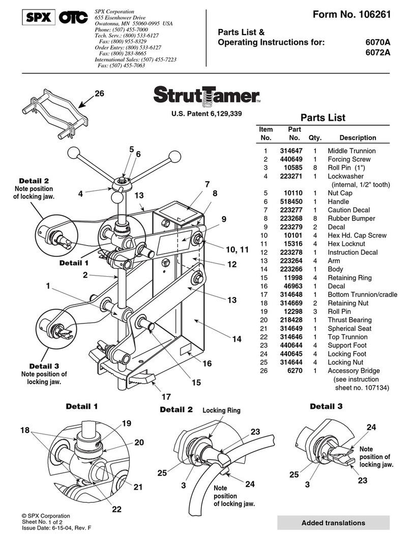
Item No. Quantity Description
2 2 Front Wheel
3 2 Washer
4 4 Snap Ring
5 3 Oil Nipple
6 2 Rod Link
7 2 Bolt
8 1 Saddle
9 2 Snap Ring
10 2 Nut
11 1 Spring
12 2 Bolt
13 1 Bolt
14 2 Snap Ring
15 1 Shaft
16 2 Rear Wheel
17 4 Nut
18 2 Snap Ring
19 1 Shaft
20 1 Washer
21 1 Pin
22 1 Connecting Bar
23 1 Spring
24 2 Snap Ring
25 1 Shaft
26 1 Inspection Plate
27 1 Cylinder Pump Assy.
28 1 Snap Ring
29 2 Washer
30 1 O-ring
32 1 Piston Ring
33 1 Sealing Washer
34 1 O-ring
35 1 O-ring Retainer
36 1 Snap Ring
38 1 Oil Filler Plug
Item No. Quantity Description
39 3 Pin
40 2 Steel Ball
41 1 Steel Ball
42 1 Spring
43 1 Copper Washer
44 1 Bolt
45 1 Steel Ball
46 1 Ball Seat
47 1 Spring
48 1 Screw
49 1 Sealing Washer
50 1 Bolt
51 1 Sealing Washer
52 1 Pin
53 1 Release Valve Rod
54 1 Cylinder Pump Plunger
55 1 Pin
56 1 Handle Socket
57 1 Pedal
58 1 Nut
59 1 Washer
60 1 Bolt
61 1 Handle
62 2 Sleeve
63 1 Knob
64 1 Pin
65 1 Control Rod
66 1 Spring
67 3 Washer
68 3 Screw
69 1 Rod Joint
70 1 Spring
71 1 Universal Joint Assy.
72 1 Convey Rod
73 1 Washer
Parts List & Operating Instructions Form No. 520770, Sheet 1 of 3, Back
PARTS LIST

© 2003 SPX Corporation
Sheet No.
Issue Date: Rev. C, 8-13-03
Item
No. Qty. Description
No. 520771* and 520772†Seal Kits
includes :
28 1 Snap Ring
29 2 Washer
30 1 O-ring
32 1 Piston Ring
33 1 Sealing Washer
34 1 O-ring
35 1 O-ring Retainer
38 1 Oil Filler Plug
43 1 Copper Washer
49 1 Sealing Washer
No. 520773* and 520774†Power Units
include:
13 1 Bolt
27 1 Power Unit
No. 520775* and 520776†Caster Kits
include:
16 1 Rear Wheel
17 2 Nut
Replacement Kits
Item
No. Qty. Description
No. 520777* and 520778†Wheel Kits
include:
2 1 Front Wheel
3 1 Washer
4 1 Snap Ring
5 1 Oil Nipple
No. 520779* and 520780†Saddle Kits
include:
8 1 Saddle
No. 520781* and 520782†Lift Arm
Spring Kits include:
11 1 Spring
12 2 Bolt
14 2 Snap Ring
15 1 Shaft
No. 520789 Handle Assembly Kit
includes:
61 1 Handle
62 2 Sleeve
63 1 Knob
64 1 Pin
65 1 Control Rod
66 1 Spring
67 3 Washer
68 3 Screw
69 1 Rod Joint
70 1 Spring
71 1 Universal Joint
Assy.
72 1 Convey Rod
73 1 Washer
No. 520790 Handle Pivot Kit includes:
18 2 Snap Ring
19 1 Shaft
56 1 Handle Socket
Item
No. Qty. Description
The following kits are used on both the 1505B and the 1510B units.
Numbers followed by an asterisk (*) are kits used on 1505B units.
Numbers followed by this symbol (†) are kits used on 1510B units.
Parts List & Operating Instructions Form No. 520770
2 of 3
No. 520791 Foot Pedal Kit includes:
57 1 Pedal
No. 520792 Handle Retaining Bolt Kit includes:
58 1 Nut
59 1 Washer
60 1 Bolt
No. 520793 Handle Return Spring Kit includes:
23 1 Spring
No. 520794 Release Valve Kit includes:
40 1 Steel Ball
51 1 Sealing Washer
52 1 Pin
53 1 Release Valve Rod
Item
No. Qty. Description
Item
No. Qty. Description
Item
No. Qty. Description
No. 520783* and 520784†Pump Plunger/
Connect Bar Kits include:
20 1 Washer
21 1 Pin
22 1 Connecting Bar
24 2 Snap Ring
25 1 Shaft
54 1 Cylinder Pump
Plunger
55 1 Pin
No. 520785* and 520786†Level Link Arm Kits
include:
4 2 Snap Ring
6 2 Rod Link
7 2 Bolt
9 2 Lock Washer
10 2 Nut
No. 520787* and 520788†Inspection Plate
Kits include:
26 1 Inspection Plate
No. 520795 Pump Hardware Kit
includes:
36 1 Snap Ring
39 3 Pin
40 2 Steel Ball
41 1 Steel Ball
42 1 Spring
43 1 Copper Washer
44 1 Bolt
45 1 Steel Ball
46 1 Ball Seat
47 1 Spring
48 1 Screw
49 1 Sealing Washer
50 1 Bolt
No. 520796 Grease Zerk Kit includes:
5 1 Oil Nipple

Setup
Assemble the Handle
1. Loosen the bolt on the handle socket.
2. Insert the handle.
3. Tighten the bolt.
Bleed Air from the Service Jack
Air can accumulate within a hydraulic system during shipment or after
prolonged use. This entrapped air causes the jack to respond slowly or feel
“spongy.” To remove the air:
1. Open the release valve by turning the release knob counterclockwise.
2. Pump the jack handle six full strokes.
3. Close the release valve by turning the release knob clockwise.
4. Pump the jack handle or foot pedal until the lift arm is fully extended.
5. Lower the lift arm by turning the release knob counterclockwise. If the
jack does not immediately respond, repeat Steps 2–4. Position A
WARNING: To prevent personal injury and damage to equipment,
•
Read, understand, and follow all instructions and safety precautions.
•
Before using the service jack to lift a vehicle, refer to the vehicle service manual for recommended lifting
surfaces on the vehicle chassis.
•
Wear eye protection that meets ANSI Z87.1 and OSHA standards.
•
Inspect the jack before each use; do not use the jack if it’s damaged, altered, or in poor condition.
•
Use the jack for lifting purposes; use approved safety stands to support the axles before working on the
vehicle.
•
Never exceed the rated lifting capacity of the jack.
•
Use the jack on a hard, level surface. The jack must be free to roll without any obstructions while lifting or
lowering the vehicle. The wheels of the vehicle must be in the straight-ahead position, and the hand brake
must be released.
•
Center the axle on the jack saddle. Off-center loads can damage seals and cause jack failure.
•
Lift only dead weight. Do not move the jack while it is supporting a vehicle.
•
Stay clear of lifted loads. Use approved safety stands to support the axles before making repairs.
•
Do not adjust the safety valve.
•
Lower the jack slowly and carefully while watching the position of the jack saddle.
•
Use only approved hydraulic fluid (Chevron AW Hydraulic Oil MV or equivalent). The use of alcohol, hydraulic brake fluid,
or transmission oil could damage seals and result in jack failure.
This guide cannot cover every situation, so always do the job with safety first.
Safety Precautions
Operating Instructions
(Refer to illustrations above)
Control rod in Position A: Allows you to pump jack using the handle.
Control rod in Position B: Locks handle in place.
Lifting Operation
1. Turn release knob counterclockwise fully.
2. Position the jack under the vehicle. IMPORTANT: Use the vehicle manufacturer’s recommended lifting points on the chassis.
3. Pump the jack handle or the foot pedal until the saddle touches the vehicle. Check the placement of the saddle lugs. Finish lifting the
vehicle.
4. Place approved safety stands under the vehicle at points that will provide stable support. Before working on the vehicle, SLOWLY
lower the vehicle onto the safety stands.
Lowering Operation
1. SLOWLY turn release knob counterclockwise.
Parts List & Operating Instructions Form No. 520770, Sheet 2 of 3, Back
Position B
Release Knob
Control Rod

© 2003 SPX Corporation
Sheet No.
Issue Date: Rev. C, 8-13-03
Troubleshooting Guide
Repair procedures must be performed in a dirt-free environment by qualified personnel who are familiar with this equipment.
Jack does not lift 1. Release valve is open.
1. Close release valve.
2. Low/no oil in reservoir.
2. Fill with oil and bleed system.
3. Air-locked system.
3. Bleed system.
4. Load is above capacity of jack.
4. Use correct equipment.
5. Delivery valve and/or bypass
5. Clean to remove dirt or foreign
valve not working correctly.
matter. Replace oil.
6. Packing worn out or defective.
6. Install seal kit.
Jack lifts only partially 1. Too much or not enough oil.
1. Check oil level.
Jack advances slowly 1. Pump not working correctly.
1. Install seal kit, or replace power unit.
2. Leaking seals.
2. Install seal kit.
Jack lifts load, but doesn't hold 1. Cylinder packing is leaking.
1. Install seal kit.
2. Valve not working correctly
2. Inspect valves. Clean and
(suction, delivery, release, or
repair seat surfaces.
bypass).
3. Air-locked system.
3. Bleed system.
Jack leaks oil 1. Worn or damaged seals.
1. Install seal kit.
Jack will not retract 1. Release valve is closed.
1. Open or clean release valve.
Jack retracts slowly 1. Cylinder damaged internally.
1. Send jack to OTC authorized
service center for repair.
2. Link section is binding.
2. Lubricate link section.
Trouble Cause Solution
a. Cracked or damaged housing e. Malfunctioning swivel heads or adjusting screws
b. Excessive wear, bending, or other damage f. Loose hardware
c. Leaking hydraulic fluid g. Modified or altered equipment
d. Scored or damaged piston rod
Preventive Maintenance
IMPORTANT: Dirt is the greatest single cause of failure in hydraulic units.
Keep the service jack clean and well lubricated to prevent foreign matter
from entering the system. If the jack has been exposed to rain, snow, sand,
or grit, it must be cleaned before it is used.
1. Store the jack in a well-protected area where it will not be exposed to corrosive
vapors, abrasive dust, or any other harmful elements.
2. Refer to Figure 2, and regularly (at least once per month) lubricate the moving
parts shown.
3. Add grease to upper arm grease nipple (shown) every three months.
4. Replace the oil in the reservoir at least once per year. To check the oil level,
place the service jack on level ground and lower the lift arm completely.
Remove the filler plug located under the top shroud. The oil level should be
within 3/8" of the filler plug hole. If necessary, add approved anti-wear
hydraulic jack oil, and install the filler plug again. IMPORTANT: The use of
alcohol, hydraulic brake fluid, detergent motor oil, or transmission oil could damage the seals and result in jack failure.
5. Inspect the jack before each use. Take corrective action if any of the following problems are found:
Grease Nipple
Figure 2
3 of 3
Parts List & Operating Instructions Form No. 520770
This manual suits for next models
1
Table of contents
Other SPX Tools manuals
Popular Tools manuals by other brands

Axminster
Axminster Woodturning Deluxe Pen Press instructions

Toro
Toro 137-0592 installation instructions
probst
probst 5310.0372 operating instructions

forstreich maschinebau
forstreich maschinebau TR 24 operating instructions
Trelawny SPT
Trelawny SPT VL203EX Operation and maintenance manual
Topcon
Topcon AT-B2 instruction manual
