stärke der Türstation zu verändern,
um eine klare Sprachübertragung zu
ermöglichen.
Gehäusefront oben auf der Grund-6
platte einhängen und schließen. Die
Inbusschraube an der Unterseite des
Gehäuse festdrehen.
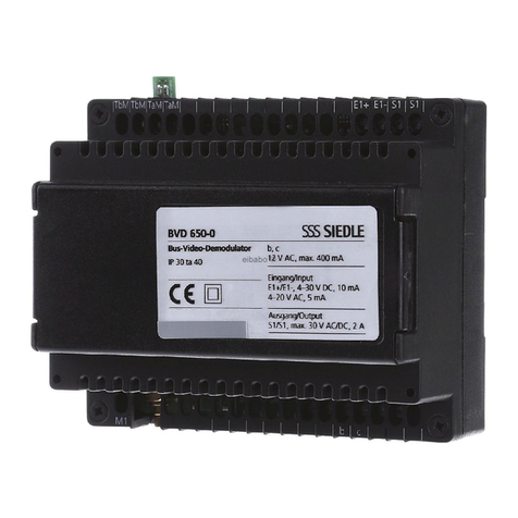
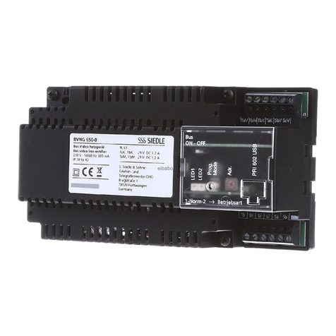
Montage Bus-Netzgerät
Netzgerät auf Hutschiene montie-7
ren (Verteilung).
AP-Montage mit Zubehör ZAP 9-08
möglich. (nicht im Lieferumfang)
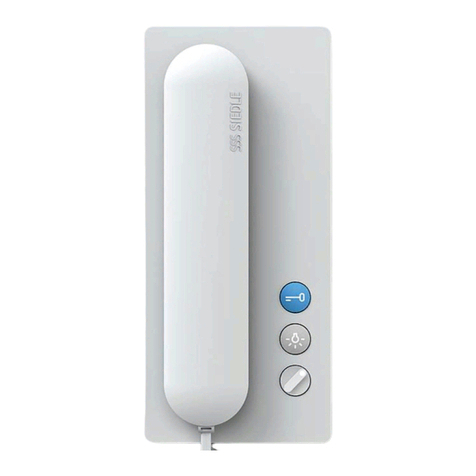
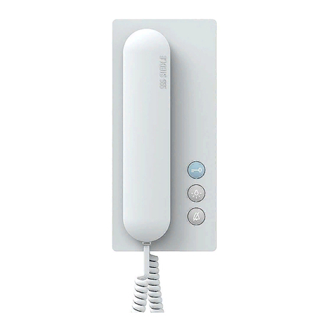
Montage Bus-Telefon
Kabel auf 80 mm abmanteln.
Öffnen des Gerätes von der Rück-9
seite; dazu Rasthebel eindrücken.
Empfohlene Einbauhöhe ca.10
1,50 m/4,9 ft bis Gerätemitte.
Bei Montage direkt auf der Wand11
die Grundplatte mit 4 Schrauben
befestigen. Einbaulage Oben/Top
beachten.
Bei Montage auf Schalterdose12
Schraubenöffnungen in der Geräte-
mitte verwenden. Einbaulage Oben/
Top beachten.
Installation nach Anschluss-13
plan vornehmen. Die Adern des
Installationskabels müssen innerhalb
des freien Installationsraumes in der
Grundplatte verstaut werden.
Farbigen Stecker der Federzug-14
schnur in die Buchse am Gehäuse
einführen, Stecker muss hörbar
einrasten.
Anderes Ende der Federzug-15
schnur in den Hörer einstecken, bis
Stecker einrastet. Die Verbindung ist
nicht mehr lösbar.
Bei der Plug+Play Programmie-16
rung Gehäuse erst während der
Programmierung schließen. Gehäuse
oben auf der Grundplatte einhängen
und mit leichtem Druck schließen.
Demontage Haustelefon
Zum Abnehmen des Gehäuses17
mit einem Schlitz-Schraubendreher
die Verriegelung nach oben drücken.
Leiterplatte und Hörer verbleiben am
Gehäuse-Oberteil.
Beschriftung
Namensschild von der Außenseite18
z. B. mit einem Schlitzschraubendre-
her vorsichtig öffnen und Namens-
schild entnehmen. Zum Einsetzen
das Namensschild mit leichtem
Druck einrasten.
Installation
Anschluss nach Anschlussplan
AS-TVHa-1/1 vornehmen.
Anschlussplan für 125 V Ausfüh-
rung.
TÖ = Türöffner
ERT = Etagenruftaste
Li = Licht
Reichweite Video-Set-Netzgerät zu
Türstation max. 50 m/164 ft, Video-
Set-Netzgerät zum entferntesten
Bus-Telefon 50 m/164 ft bei 0,8 mm
Leitungsmaterial. Nach erfolgter
Installation muss das Video-Set
programmiert werden.
Klemmenbelegung
TaK/TbK In-Home-Bus: Anschluss
zu Video-Set-Netzgerät VSNG 850-...
Technische Daten CV 850-...
•FarbsystemPAL
•BildaufnehmerCCD-Sensor1/3”
752 x 582 Bildpunkte (horizontal/
vertikal)
•Objektiv3,7mm
•Blickwinkelhorizontalca.60°,
vertikalca.50°
•zusätzlichermechanischerVerstell-
bereichumca.30°horizontalund
vertikal
•Auösunghorizontal450Linien
•integrierteInfrarotbeleuchtung
•Temperaturbereich
-20°Cbis+40°C
•VersorgungüberIn-Home-Bus:
Video
•SchutzartTürlautsprecherIP54
•Abmessungen82x226x39mm
Technische Daten VSNG 850-0
•Eingangsspannung
230 V AC +/-10%, 50-60 Hz
•Primärsicherung250mA(L)250V
•Stromaufnahme200mA
•Bus-Spannung27,5VDC0,5A
geregelt +/- 5%, kurzschlussfest an
Klemmen TaK/TbK und TaM/TbM
•12VAC,1A
•Umgebungstemperatur
0°Cbis+40°C,Betriebineiner
Höhenlage zwischen -20 und
2000 m über NN
•max.relativeLuftfeuchte60%
•SchutzartIP30
•Abmessungen162x89x60mm
Technische Daten VSNG 850-1
•Eingangsspannung
125 V AC +/-10%, 50-60 Hz
•Primärsicherung500mA(L)250V
•Stromaufnahme360mA
•weiteretechnischeAngabensiehe
oben
Technische Daten
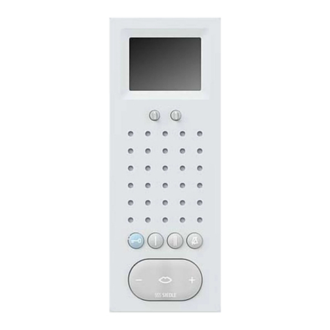
BTSV/BFSV 850-...
•VersorgungüberIn-Home-Bus
•Klingellautstärke:max.83dB(A)
•Farbmonitor6,3cm(2,5”)
•StromaufnahmebeiVersorgung
über +M/-M max. 300 mA
•PotentialfreierKontaktS1/S1max.
15 V AC, 30V DC, 1A Schaltzeitzeit
0,4 Sek. – 19 Min.
•AbmessungenBxHxT
90 x 261 x 45 mm mit Hörer bzw.
90 x 261 x 27 mm ohne Hörer
