15
Polaris General
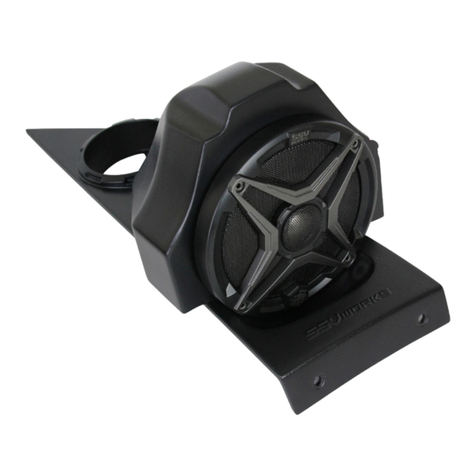
6.5” Speaker Front Kick Panels
!
Please read and understand these
instructions completely before
installation to avoid possible injury, or
damage to the accessory or vehicle.
WARRANTY INFORMATION:
All SSV Works enclosures are covered by a limited lifetime warranty against defects
in material or workmanship. All SSV Works Electronics are covered by a limited 1
year warranty against defects in material or workmanship. All Kicker Speakers are
covered by a limited 1 year warranty against defects in material or workmanship. All
Kicker Ampli ers are covered by a limited 2 year warranty against defects in material
or workmanship. Labor for replacement of defective components is not covered.
Contact SSV Works for further warranty information.
TOOLS NEEDED FOR INSTALLATION
CREASELINE
CREASELINE
PASSENGER SIDE
CREASELINE
CREASELINE
DRIVER SIDE
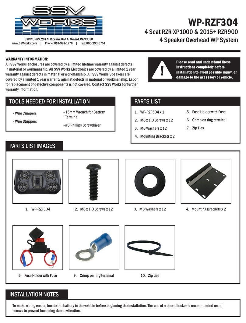
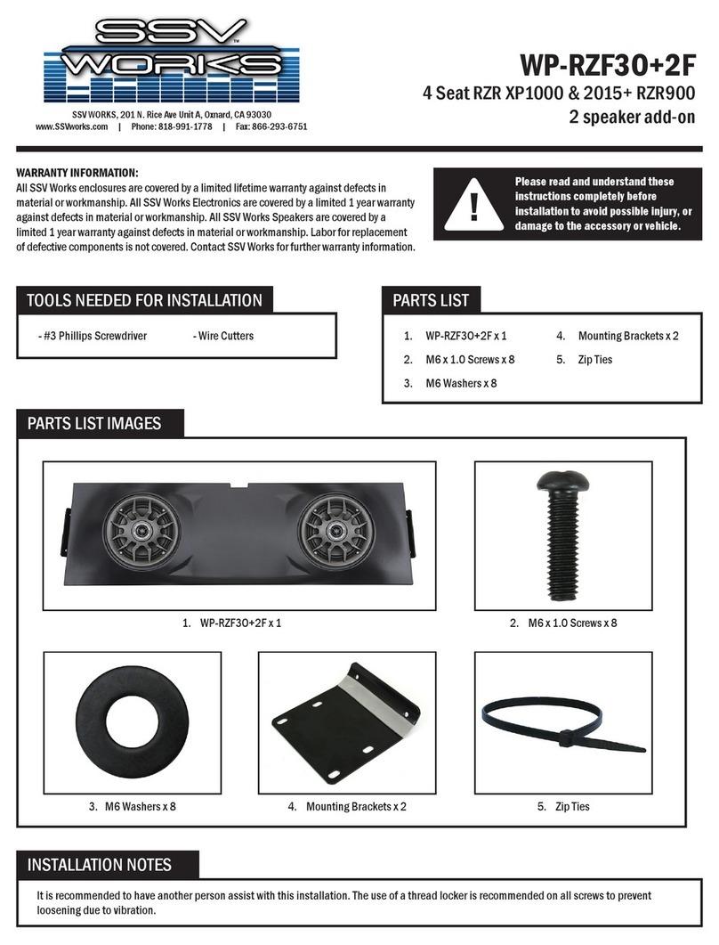
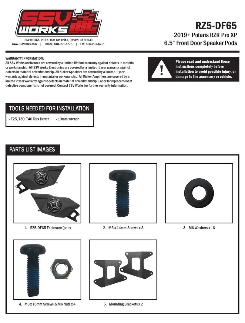
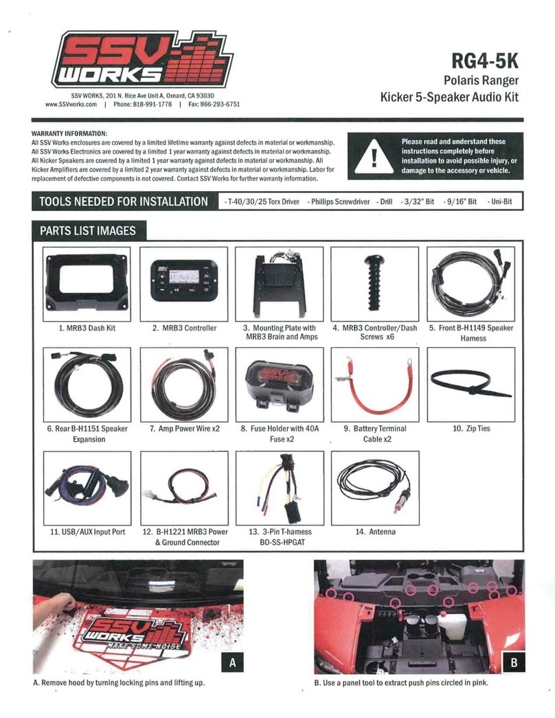
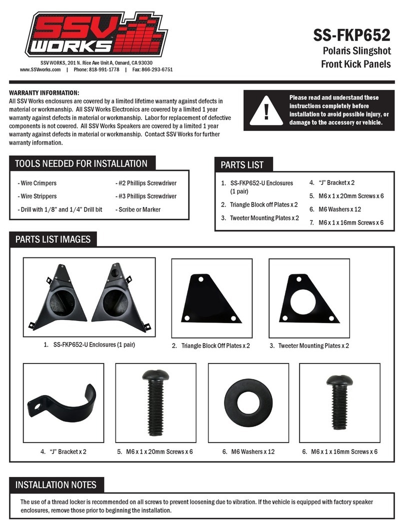
2. M6 x 16mm Screws x 6
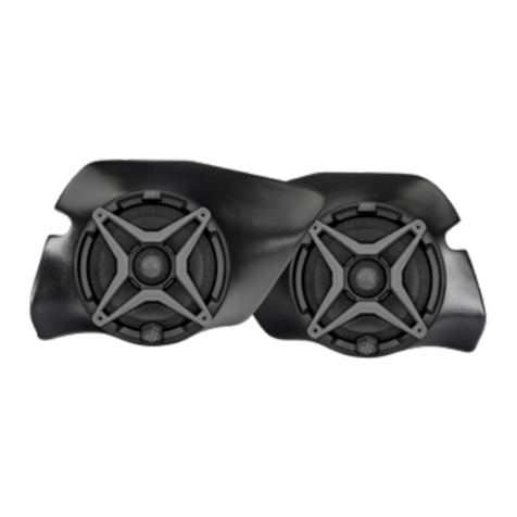
1. GN-F65 Enclosures
(1 pair)
4. Drll Template
3. M6 Washers x 6
- T-30 Torx Driver - Drill with 1/4” Drill bit - Scribe or Punch tool
Polaris General
6.5” Speaker Front Kick Panels
!
Please read and understand these
instructions completely before
installation to avoid possible injury, or
damage to the accessory or vehicle.
WARRANTY INFORMATION:
All SSV Works enclosures are covered by a limited lifetime warranty against defects
in material or workmanship. All SSV Works Electronics are covered by a limited 1
year warranty against defects in material or workmanship. All Kicker Speakers are
covered by a limited 1 year warranty against defects in material or workmanship. All
Kicker Ampli ers are covered by a limited 2 year warranty against defects in material
or workmanship. Labor for replacement of defective components is not covered.
Contact SSV Works for further warranty information.
TOOLS NEEDED FOR INSTALLATION
PARTS LIST IMAGES
CREASELINE
CREASELINE
PASSENGER SIDE
CREASELINE
CREASELINE
2. M6 x 16mm Screws x 6
1. GN-F65 Enclosures
(1 pair)
4. Drll Template
3. M6 Washers x 6
- T-30 Torx Driver - Drill with 1/4” Drill bit - Scribe or Punch tool
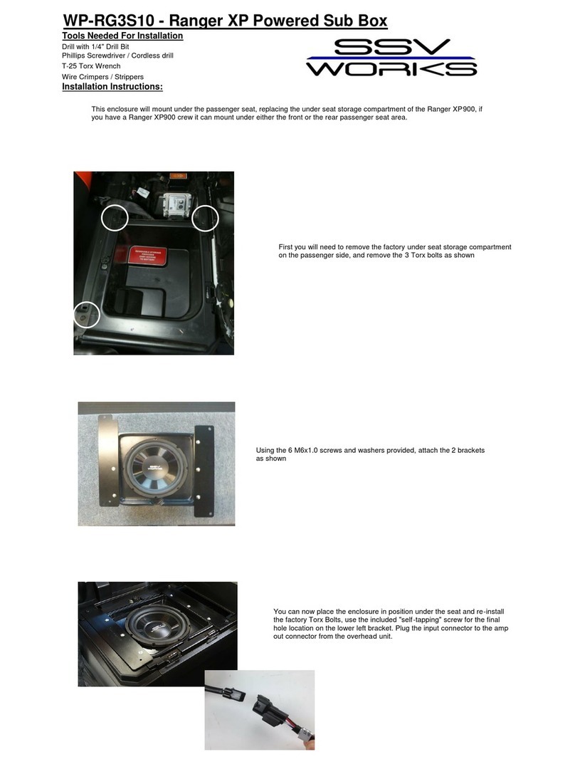
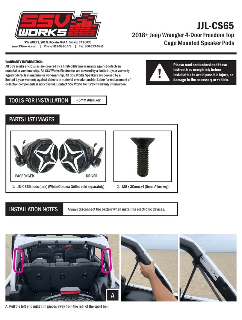
C. Using a ¼ drill bit, drill holes for mounting of kick Pods .
E. Use the provided M6 screws and washers and loosely tighten
the pod in place through the drilled holes. Once all screws
have been loosely installed, tighten down by hand.
F. Route the speaker wire away from any moving parts and any
sharp metal, then connect to the ampli er.
C
E F
D. Place enclosure in location for mounting.
D
A. Cut out the INSIDE template (Driver/Passenger) along the cut
line. Position the template on kick panel above the foot rest
making sure to line up arrows on template to the curves of the
panel as seen on image A.
B. Using a scribing tool, mark the center of the 3 drill points
illustrated on the template as shown on image B.
AB
SSV WORKS, 201 N. Rice Ave Unit A, Oxnard, CA 93030
www.SSVworks.com | Phone: 818-991-1778 | Fax: 866-293-6751


