ST X-NUCLEO-LPM01A User manual

March 2018 UM2243 Rev 2 1/41
1
UM2243
User manual
STM32 Nucleo expansion board
for power consumption measurement
Introduction
The X-NUCLEO-LPM01A expansion board is a programmable power supply source (from
1.8 V to 3.3 V) with advanced power consumption measurement capability.
It performs consumption averaging (static measurement up to 200 mA) as well as real-time
analysis (dynamic measurement up to 50 mA with 100 kHz bandwidth).
The X-NUCLEO-LPM01A operates either in standalone mode (using its LCD, joystick and
button to display static measurements), or in controlled mode connected to a host PC via
USB (using the STM32CubeMonitor-Power software tool with its comprehensive graphical
user interface).
It can be used to supply and measure the consumption of STM32 Nucleo-32, Nucleo-64 or
Nucleo-144 boards using Arduino™ connectors. Alternatively, it supplies and measures the
consumption of any target connected by wires via the basic connector.
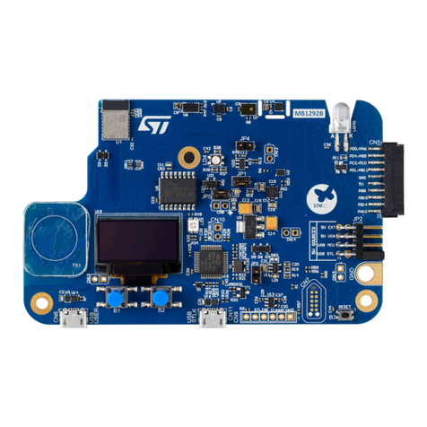
Figure 1. X-NUCLEO-LPM01A
1. Picture is not contractual.
www.st.com

Contents UM2243
2/41 UM2243 Rev 2
Contents
1 Features . . . . . . . . . . . . . . . . . . . . . . . . . . . . . . . . . . . . . . . . . . . . . . . . . . . 7
2 Product marking . . . . . . . . . . . . . . . . . . . . . . . . . . . . . . . . . . . . . . . . . . . . 8
3 System requirements . . . . . . . . . . . . . . . . . . . . . . . . . . . . . . . . . . . . . . . . 8
4 Software tool and embedded software . . . . . . . . . . . . . . . . . . . . . . . . . . 9
4.1 Embedded software . . . . . . . . . . . . . . . . . . . . . . . . . . . . . . . . . . . . . . . . . . 9
4.2 PC software tool . . . . . . . . . . . . . . . . . . . . . . . . . . . . . . . . . . . . . . . . . . . . . 9
5 Ordering information . . . . . . . . . . . . . . . . . . . . . . . . . . . . . . . . . . . . . . . . 9
6 Hardware layout and configuration . . . . . . . . . . . . . . . . . . . . . . . . . . . . 10
6.1 X-NUCLEO-LPM01A layout . . . . . . . . . . . . . . . . . . . . . . . . . . . . . . . . . . . .11
7 Supplying power to the X-NUCLEO-LPM01A . . . . . . . . . . . . . . . . . . . . 13
7.1 Power source from an USB host port (default setting) . . . . . . . . . . . . . . . 13
7.2 Power source from a USB charger . . . . . . . . . . . . . . . . . . . . . . . . . . . . . . 14
7.3 Power source from an external DC power supply. . . . . . . . . . . . . . . . . . . 15
7.4 Power source from the 5 V pin of the Arduino Uno or Arduino
Nano connectors . . . . . . . . . . . . . . . . . . . . . . . . . . . . . . . . . . . . . . . . . . . 16
7.5 X-NUCLEO-LPM01A power consumption . . . . . . . . . . . . . . . . . . . . . . . . 16
8 Power supply connections of a target board . . . . . . . . . . . . . . . . . . . . 17
8.1 Settings for use of the Arduino Uno connectors with
Nucleo64 and Nucleo144 use cases . . . . . . . . . . . . . . . . . . . . . . . . . . . . 19
8.2 Settings for use of the Arduino Nano connectors in a
Nucleo32 use case . . . . . . . . . . . . . . . . . . . . . . . . . . . . . . . . . . . . . . . . . . 20
8.3 Power supply connections of a target board with basic
connector CN14 . . . . . . . . . . . . . . . . . . . . . . . . . . . . . . . . . . . . . . . . . . . . 22
9 Static current measurement principle . . . . . . . . . . . . . . . . . . . . . . . . . . 23
10 Dynamic current measurement principle . . . . . . . . . . . . . . . . . . . . . . . 24
10.1 Dynamic current block diagram description . . . . . . . . . . . . . . . . . . . . . . . 25

UM2243 Rev 2 3/41
UM2243 Contents
4
10.2 Behavior for dynamic current measurements . . . . . . . . . . . . . . . . . . . . . . 25
10.3 Dynamic current measurements special care . . . . . . . . . . . . . . . . . . . . . 26
11 Standalone mode using embedded user interface . . . . . . . . . . . . . . . 27
12 Host-controlled mode with a PC . . . . . . . . . . . . . . . . . . . . . . . . . . . . . . 28
13 Trigger signals between the X-NUCLEO-LPM01A
and the target board . . . . . . . . . . . . . . . . . . . . . . . . . . . . . . . . . . . . . . . . 29
13.1 Trigger signal from the target board to the
X-NUCLEO-LPM01A . . . . . . . . . . . . . . . . . . . . . . . . . . . . . . . . . . . . . . . . 29
13.2 Trigger signal from X-NUCLEO-LPM01A to target board . . . . . . . . . . . . . 31
14 Extension connector CN11 . . . . . . . . . . . . . . . . . . . . . . . . . . . . . . . . . . . 33
14.1 Extension connector used with Arduino Uno connectors . . . . . . . . . . . . . 33
14.2 Extension connector used with Arduino Nano connectors . . . . . . . . . . . . 34
14.3 Switch to select the type of daughterboard . . . . . . . . . . . . . . . . . . . . . . . 34
15 How to adapt an STM32L432 Nucleo-32/Nucleo-64/
Nucleo-144 to power the MCU from the Arduino
AREF pin . . . . . . . . . . . . . . . . . . . . . . . . . . . . . . . . . . . . . . . . . . . . . . . . . 35
15.1 How to adapt an STM32L432 Nucleo-32
to power the MCU from the Arduino AREF pin . . . . . . . . . . . . . . . . . . . . 35
15.2 How to adapt an STM32L476 Nucleo-64
to power the MCU from the Arduino AREF pin . . . . . . . . . . . . . . . . . . . . 35
15.3 How to adapt an STM32L496 Nucleo-144
to power the MCU from the Arduino AREF pin . . . . . . . . . . . . . . . . . . . . 36
16 Statement of compliance to local legislation . . . . . . . . . . . . . . . . . . . . 37
16.1 FCC Compliance Statement . . . . . . . . . . . . . . . . . . . . . . . . . . . . . . . . . . . 37
16.1.1 Part 15.19 . . . . . . . . . . . . . . . . . . . . . . . . . . . . . . . . . . . . . . . . . . . . . . . 37
16.1.2 Part 15.105 . . . . . . . . . . . . . . . . . . . . . . . . . . . . . . . . . . . . . . . . . . . . . . 37
16.1.3 Part 15.21 . . . . . . . . . . . . . . . . . . . . . . . . . . . . . . . . . . . . . . . . . . . . . . . 37
16.2 IC Compliance Statement . . . . . . . . . . . . . . . . . . . . . . . . . . . . . . . . . . . . . 37
16.2.1 Compliance Statement . . . . . . . . . . . . . . . . . . . . . . . . . . . . . . . . . . . . . . 37
16.2.2 Déclaration de conformité . . . . . . . . . . . . . . . . . . . . . . . . . . . . . . . . . . . 38
16.3 CE Compliance Statement . . . . . . . . . . . . . . . . . . . . . . . . . . . . . . . . . . . . 38

UM2243 Rev 2 5/41
UM2243 List of tables
5
List of tables
Table 1. Ordering Information . . . . . . . . . . . . . . . . . . . . . . . . . . . . . . . . . . . . . . . . . . . . . . . . . . . . . . . 9
Table 2. Power input source setting summary . . . . . . . . . . . . . . . . . . . . . . . . . . . . . . . . . . . . . . . . . 13
Table 3. Power output related jumper and connector settings . . . . . . . . . . . . . . . . . . . . . . . . . . . . . 17
Table 4. Pin description of the basic connector CN14 . . . . . . . . . . . . . . . . . . . . . . . . . . . . . . . . . . . 22
Table 5. Reference documents. . . . . . . . . . . . . . . . . . . . . . . . . . . . . . . . . . . . . . . . . . . . . . . . . . . . . 39
Table 6. Document revision history . . . . . . . . . . . . . . . . . . . . . . . . . . . . . . . . . . . . . . . . . . . . . . . . . 40

List of figures UM2243
6/41 UM2243 Rev 2
List of figures
Figure 1. X-NUCLEO-LPM01A . . . . . . . . . . . . . . . . . . . . . . . . . . . . . . . . . . . . . . . . . . . . . . . . . . . . . . 1
Figure 2. Hardware block diagram . . . . . . . . . . . . . . . . . . . . . . . . . . . . . . . . . . . . . . . . . . . . . . . . . . . 10
Figure 3. X-NUCLEO-LPM01A layout top view . . . . . . . . . . . . . . . . . . . . . . . . . . . . . . . . . . . . . . . . . 11
Figure 4. X-NUCLEO-LPM01A layout bottom view . . . . . . . . . . . . . . . . . . . . . . . . . . . . . . . . . . . . . . 12
Figure 5. JP3 (USB setting) . . . . . . . . . . . . . . . . . . . . . . . . . . . . . . . . . . . . . . . . . . . . . . . . . . . . . . . . 14
Figure 6. JP3 and JP2 (USB charger setting) . . . . . . . . . . . . . . . . . . . . . . . . . . . . . . . . . . . . . . . . . . 14
Figure 7. JP3 and CN7 (Ext Pwr setting) . . . . . . . . . . . . . . . . . . . . . . . . . . . . . . . . . . . . . . . . . . . . . . 15
Figure 8. JP3 (power from Arduino setting) . . . . . . . . . . . . . . . . . . . . . . . . . . . . . . . . . . . . . . . . . . . . 16
Figure 9. CN4 and CN13 +5V pin assignment. . . . . . . . . . . . . . . . . . . . . . . . . . . . . . . . . . . . . . . . . . 16
Figure 10. Pins AREF and 3V3 of Arduino Uno connectors CN4 and CN3 . . . . . . . . . . . . . . . . . . . . . 18
Figure 11. Pins AREF and 3V3 of Arduino Nano connectors, output connector CN14 and
jumpers JP1, JP9, JP10, JP4 . . . . . . . . . . . . . . . . . . . . . . . . . . . . . . . . . . . . . . . . . . . . . . . 18
Figure 12. Jumper setting for Arduino with Nucleo target board . . . . . . . . . . . . . . . . . . . . . . . . . . . . . 19
Figure 13. STM32 Nucleo64 target board plugged into the X-NUCLEO-LPM01A. . . . . . . . . . . . . . . . 20
Figure 14. STM32 Nucleo32 target board plugged into the X-NUCLEO-LPM01A. . . . . . . . . . . . . . . . 21
Figure 15. Basic connector CN14 . . . . . . . . . . . . . . . . . . . . . . . . . . . . . . . . . . . . . . . . . . . . . . . . . . . . 22
Figure 16. Static current measurement principle . . . . . . . . . . . . . . . . . . . . . . . . . . . . . . . . . . . . . . . . . 23
Figure 17. Dynamic current block diagram . . . . . . . . . . . . . . . . . . . . . . . . . . . . . . . . . . . . . . . . . . . . . 24
Figure 18. Embedded user interfaces elements . . . . . . . . . . . . . . . . . . . . . . . . . . . . . . . . . . . . . . . . . 27
Figure 19. Arduino D7 trigger signal from target schematics. . . . . . . . . . . . . . . . . . . . . . . . . . . . . . . . 29
Figure 20. Arduino Uno D7 trigger signal from target and solder bridges SB26 . . . . . . . . . . . . . . . . . 30
Figure 21. Arduino Nano D7 trigger signal from target . . . . . . . . . . . . . . . . . . . . . . . . . . . . . . . . . . . . 30
Figure 22. Arduino D2, D3 trigger signal to target schematics . . . . . . . . . . . . . . . . . . . . . . . . . . . . . . 31
Figure 23. Arduino Uno D2, D3 trigger signal to target and solder bridges SB3, SB5. . . . . . . . . . . . . 31
Figure 24. Arduino Nano D2, D3 trigger signal to target . . . . . . . . . . . . . . . . . . . . . . . . . . . . . . . . . . . 32
Figure 25. Extension connector CN11 with Arduino Uno. . . . . . . . . . . . . . . . . . . . . . . . . . . . . . . . . . . 33
Figure 26. Extension connector CN11 with Arduino Nano. . . . . . . . . . . . . . . . . . . . . . . . . . . . . . . . . . 34
UM2243 Rev 2 7/41
UM2243 Features
40
1 Features
The X-NUCLEO-LPM01A expansion board has the following features:
•Data acquisition and data treatment unit: STM32L496VGT6 Ultra-low-power MCU with
80 MHz/100 DMIPS Arm®Cortex®-M4 core, 1 Mbyte of Flash memory, 320 Kbytes of
SRAM, 3x 12-bit ADC at 5 Msamples/s, 2 x comparators
•Programmable voltage source from 1.8 V to 3.3 V
•Static current measurement from 1 nA to 200 mA
•Dynamic measurements:
– 100 kHz bandwidth, 3.2 Msamples/s sampling rate
– Current from 100 nA to 50 mA
– Power measurement from 180 nW to 165 mW
– Energy measurement computation by power measurement time integration
•Target board connections:
– Arduino™ Nano connector (for example to connect a Nucleo-32)
– Arduino™ Uno connector (for example to connect a Nucleo-64 or a Nucleo-144)
– Basic connector for wire connection to any target board
•Expansion board power supply input sources (selectable via jumper) through:
– USB micro-B
– External power (Ext Pwr) connector: from 7 V to 10 V
– Arduino Uno or Arduino Nano: pin 5 V
•Standalone mode:
– Monochrome LCD, 2 lines of 16 characters with back light
– 4-direction joystick with selection button
– Enter and Reset push-buttons
•Host-controlled mode:
– Connection to a PC through USB FS micro-B receptacle
– Command line (Virtual COM port) or STM32CubeMonitor-Power PC tool.

Product marking UM2243
8/41 UM2243 Rev 2
2 Product marking
Evaluation tools marked as ‘ES’ or ‘E’ are not yet qualified and are therefore not ready to be
used as reference designs or in production. Any consequences arising from such usage will
not be at ST's charge. In no event will ST be liable for any customer usage of these
engineering sample tools as reference designs or in production.
Example ‘E’ or ‘ES’ marking locations:
•On the targeted STM32 that is soldered on the board (for illustrations of STM32
marking, refer to the applicable STM32 datasheet at www.st.com).
•Next to the evaluation tool ordering part number. This is stuck to, or silkscreen printed
on the board.
This board features a specific STM32 device version which allows the operation of any
stack or library. This STM32 device shows a ‘U’ marking option at the end of the standard
part number and is not available for sales.
3 System requirements
•Windows®OS (XP, 7, 8, 10), Linux® 64-bit or macOS®
•USB Type-A to Micro-B cable

UM2243 Rev 2 9/41
UM2243 Software tool and embedded software
40
4 Software tool and embedded software
4.1 Embedded software
The X-NUCLEO-LPM01A expansion board firmware is preloaded.
The latest firmware version (order code: STM32-LPM01-XN) can be downloaded from the
following web page: www.st.com/stm32softwaretools.
The firmware controls the board and provides a plug-and-play solution for current
measurement. It can be used in two main modes:
•Standalone mode: supply power to the board by a USB cable or an external +5 V
source, then follow the instructions on the LCD screen.
•Controlled by host mode: refer to Section 4.2: PC software tool.
For more information on embedded software and the FW upgrade procedure, refer to the
Getting started with PowerShield firmware user manual (UM2269) [1].
4.2 PC software tool
The X-NUCLEO-LPM01A expansion board can be controlled by a computer through a USB
port.
A computer driver for the USB virtual COM port (VCP) is required. The STM32 Virtual COM
Port Driver (reference code: STSW-STM32102) can be downloaded from www.st.com.
The board can be controlled either:
•Via a COM port terminal with commands. Type the command ‘help’ for a list of
commands available. For more information on commands, please refer to the
X-NUCLEO-LPM01A PowerShield firmware user manual [1].
•Via a graphical user interface using the STM32CubeMonitor-Power software tool (order
code: STM32CubeMonPwr) available at www.st.com/stm32softwaretools. For more
information on STM32CubeMonitor-Power, please refer to the STM32CubeMonitor-Power
software tool for power and ultra-low-power measurements user manual (UM2202) [2].
5 Ordering information
To order the STM32 Nucleo expansion board for power consumption measurement, refer to
Table 1.
Table 1. Ordering Information
Order Code Description
X-NUCLEO-LPM01A STM32 Nucleo expansion board for power consumption measurement

Hardware layout and configuration UM2243
10/41 UM2243 Rev 2
6 Hardware layout and configuration
The X-NUCLEO-LPM01A STM32 Nucleo expansion board is designed around the
STM32L496VGT6 (100-pin in LQFP100 package). Figure 2: Hardware block diagram
illustrates the connection between STM32L496 and peripherals. The Figure 3: X-NUCLEO-
LPM01A layout top view and Figure 4: X-NUCLEO-LPM01A layout bottom view help to
locate these features on the X-NUCLEO-LPM01A board.
Figure 2. Hardware block diagram
06Y9
h^Kd'ϮϬĨƵůůͲ
ƐƉĞĞĚ
'W/KƐ
'W/KƐ
>^
h^ŵŝĐƌŽͲ
ĐŽŶŶĞĐƚŽƌ
ϯϮŬ,njƌLJƐƚĂů
670/9*7
ƐƚĂƚŝĐĐƵƌƌĞŶƚ
ŵĞĂƐƵƌĞŵĞŶƚ
Ͳ
н
,/ƐŚƵŶƚ
>KƐŚƵŶƚ
ϭŶʹϮϬϬŵ
ϭϮͲďŝƚ
E>K'DhyͲWdž
ϭϮͲďŝƚ
ϭϮͲďŝƚ
ϭϮͲďŝƚ
ƉƌŽŐƌĂŵŵĂďůĞ
ϭϴsƚŽϯϯs
ƌĞŐƵůĂƚŽƌ
ϱsͺsh^
'W/KƐ
ĚĞĐŽƵƉ
:Wϰ
:Wϭ
ŶŽƌŵĂů
ƚĞƐƚ
:Wϯ
Eϳ
džƚWǁƌ
ϯϯs
ƌĞŐƵůĂƚŽƌ
Z
h^
džƚ
нͲ
9
$UGXLQR
8QR1DQR
ϱsͺĂƉƉůŝ
ϱs
ƌĞŐƵůĂƚŽƌ
h^ͺWtZͺE
s
ϯϯs
ƌĞŐƵůĂƚŽƌ ϯϯsͺĂƉƉůŝ
:WϮ
h^ͺ,Z'Z
KKdϬ
^ϯ
ƐǁŝƚĐŚ
^LJƐƚ
&ůĂƐŚ
8/&'
OLQHVRIFKDUDFWHUV
ZLWKEDFNOLJKW
'W/KƐ
н^W/
ϭũŽLJƐƚŝĐŬ
ϰEdZďƵƚƚŽŶ 'W/KƐ
/('
/'EOXHFXUUHQWWULJJHUUHDFKHG
/'UHGHUURU
/'RUDQJH2XWSXW2Q
/'JUHHQDFTXLVLWLRQRQJRLQJ
'W/KƐ
EZ^d
Ϯ
Z^dďƵƚƚŽŶ
ƉƌŽŐƌĂŵŵĂďůĞůŽĂĚ
:Wϵ
:WϭϬ
sKhd
Eϭϰ
s
ϱsͺZ
ϯsϯͺZ
Z&ͺZ
ϭϰϮϯ
ZͺϮ
Zͺϯ
Zͺϳ
^Ϯϲ
^ϱ
^ϯ
ϭ
Ϭ
EZ^d
'E
Ϯ
ϯ
ϰ
ϱ
ϲ
ϳ
ϴ
ϵ
ϭϬ
ϭϭ
ϭϮ
s/E
'E
EZ^d
нϱs
ϳ
ϲ
ϱ
ϰ
ϯ
Ϯ
ϭ
Ϭ
Z&
ϯsϯ
ϭϯ
EϭϮ Eϭϯ
$UGXLQR1DQR
ϱsͺZ
Z&ͺZ
ϯsϯͺZ
ƌĞƐĞƌǀĞĚ
ƌĞƐĞƌǀĞĚ
ƌĞƐĞƌǀĞĚ
ZͺϮ
Zͺϯ
Zͺϳ
ƌĞƐĞƌǀĞĚ
ƌĞƐĞƌǀĞĚ
ƌĞƐĞƌǀĞĚ
ƌĞƐĞƌǀĞĚ
ϮϮђ&
'W/KƐ
'E
^<ϭϯ
D/^KϭϮ
WtDDK^/ϭϭ
WtD^ϭϬ
WtDϵ
ϴ
ϳ
WtDϲ
WtDϱ
ϰ
WtDϯ
Ϯ
dyϭ
ZyϬ
Eϴ
^>ϭϱ
^ϭϰ
Z&
/KZ&
EZ^d
ϯsϯ
ϱs
'E
'E
s/E
Ϭ
ϭ
Ϯ
ϯ
ϰ
ϱ
Eϯ
Eϰ
Eϵ
$UGXLQR8QR
/E WKtZ
ϱsͺZ
Z&ͺZ
ϯsϯͺZ
ƌĞƐĞƌǀĞĚ
ƌĞƐĞƌǀĞĚ
ƌĞƐĞƌǀĞĚ
Zͺϳ
Zͺϯ
ZͺϮ
ƌĞƐĞƌǀĞĚ
ƌĞƐĞƌǀĞĚ
ƌĞƐĞƌǀĞĚ
/Ϯ
hϭϳƚĞŵƉĞƌĂƚƵƌĞƐĞŶƐŽƌ
ŽƵƚƉƵƚǀŽůƚĂŐĞ
ĐŽŵƉĞŶƐĂƚŝŽŶůŽŽƉ
Ͳ
н
,/ƐŚƵŶƚ >KƐŚƵŶƚ s
9''
WtZ
ĂŵƉůŝ
н
Ͳ
Ͳ
н
G\QDPLFFXUUHQW
PHDVXUHPHQW
SDWHQWSHQGLQJ
ϭϬϬŶʹϱϬŵ
ϭϬϬ<,njďĂŶĚǁŝĚƚŚ
Ͳ
н
ĐŽŵƉ
Ͳ
н
ĐŽŵƉ
ƚƌŝŐƐƌĐ
ĐƵƌƌƚŚƌĞ

UM2243 Rev 2 11/41
UM2243 Hardware layout and configuration
40
6.1 X-NUCLEO-LPM01A layout
Figure 3. X-NUCLEO-LPM01A layout top view
06Y9
ƌĚƵŝŶŽhŶŽ;EϯEϰEϴEϵͿ
ƌĚƵŝŶŽEĂŶŽ;EϭϮEϭϯͿ EdZďƵƚƚŽŶ;ϰͿ
:ŽLJƐƚŝĐŬ;ϭͿ
h^&^DŝĐƌŽͲ;EϱͿ
DhKKdϬŵŽĚĞ;^ϯͿ
h^ĐŚĂƌŐĞƌƐĞůĞĐƚŝŽŶ;:WϮͿ
ƉŽǁĞƌƐŽƵƌĐĞƐĞůĞĐƚŝŽŶ;:WϯͿ
/('LQGLFDWRU
%OXH5HG2UDQJH*UHHQ
Z^dďƵƚƚŽŶ;ϮͿ
ƌĞƐĞƌǀĞĚ;EϭϬͿ
džƚĞƌŶĂůƉŽǁĞƌƐŽƵƌĐĞŝŶƉƵƚ
ϳsƚŽϭϬs;EϳͿ
ĂƐŝĐĐŽŶŶĞĐƚŽƌŽƵƚƉƵƚ
ǀŽůƚĂŐĞƐŽƵƌĐĞ;EϭϰͿ
ĚĚŝƚŝŽŶĂůŽƵƚƉƵƚ
ĚĞĐŽƵƉůŝŶŐĐĂƉĂĐŝƚŽƌ
;:WϰͿ
ƚĞƐƚŶŽƌŵĂůŵŽĚĞ;:WϭͿ
2XWSXWYROWDJHVRXUFH
VHOHFWLRQ
WR$UGXLQRSLQ$5()-3
WR$UGXLQRSLQ9-3
>ϮůŝŶĞƐŽĨϭϲĐŚĂƌĂĐƚĞƌƐ
;hϭϴͿ
ƌĞƐĞƌǀĞĚ;^ϭ^ϮEϭϭͿ
ƌĞƐĞƌǀĞĚ;EϮͿ
ƌĞƐĞƌǀĞĚ;EϭͿ
ƚĞŵƉĞƌĂƚƵƌĞƐĞŶƐŽƌ;hϭϳͿ
86%)6RYHUFXUUHQW
/('/'
1. Picture is not contractual.

UM2243 Rev 2 13/41
UM2243 Supplying power to the X-NUCLEO-LPM01A
40
7 Supplying power to the X-NUCLEO-LPM01A
The X-NUCLEO-LPM01A board is designed to be powered from one of the three following
power sources:
•USB FS micro-B connector (either USB host port or USB charger) via CN5
•External DC power supply via CN7
•Arduino Uno (CN4) connector or Arduino Nano (CN13) connector via the 5V pin
See Figure 2: Hardware block diagram for details regarding the power tree, and
Figure 3: X-NUCLEO-LPM01A layout top view for connector locations.
Table 2. Power input source setting summary
Power source
from Power connection
JP3 setting JP2
setting
ARD USB Ext
USB host CN5: USB Type micro-B connector open closed open open
USB charger CN5: USB Type micro-B connector open closed open closed
Ext power supply CN7: 7 V to 10 V DC pin +
CN7: GND pin - open open closed open
Arduino Uno
connectors
CN4: pin 5V
CN4: pin GND closed open open open
Arduino Nano
connectors
CN13: pin +5V
CN13: pin GND closed open open open
Note: Regardless of the power supply input source, the X-NUCLEO-LPM01A board must be
powered by a power supply unit or by an auxiliary equipment complying with the standard
EN-60950-1: 2006+A11/2009, and must be Safety Extra Low Voltage (SELV) with limited
power capability.
7.1 Power source from an USB host port (default setting)
A jumper should be inserted in the ‘USB’ position of JP3 as shown in Figure 5: JP3 (USB
setting). No jumper should be inserted in JP2.
A USB Type-A to USB Type micro-B cable is required to supply the X-NUCLEO-LPM01A
board (CN5: USB FS micro-B connector) to a PC host USB port.
When the USB cable is connected, 5 V DC is provided by VBUS from the USB host port of
the PC. At this step, only the embedded MCU of X-NUCLEO-LPM01A is supplied. A USB
enumeration is performed between the embedded MCU and the host PC to negotiate
500 mA on VBUS. If USB enumeration succeeds, X-NUCLEO-LPM01A peripherals are
supplied and the target board supply can be enabled. Otherwise (if USB enumeration fails),
the X-NUCLEO-LPM01A peripherals are not supplied, the red LED (LD2) is turned ON and
a message is displayed on the LCD display.
If an abnormal current higher than 600 mA is drawn from the USB connector (CN5) by the
X-NUCLEO-LPM01A, an embedded current protection clamps the current and LED LD5

Supplying power to the X-NUCLEO-LPM01A UM2243
14/41 UM2243 Rev 2
(USB FS over-current LED) lights up until the over current disappears (see Figure 3: X-
NUCLEO-LPM01A layout top view to locate LD5).
Figure 5. JP3 (USB setting)
06Y9
h^
7.2 Power source from a USB charger
A jumper should be inserted in the 'USB' position of JP3 and an additional jumper should be
inserted in JP2 as shown in Figure 6: JP3 and JP2 (USB charger setting).
A USB charger (5 V DC 500 mA minimum) should be connected to the USB FS micro-B
connector, CN5. As JP2 is closed, X-NUCLEO-LPM01A peripherals are supplied (and the
target board can be supplied) from USB connector, CN5, regardless of whether or not USB
enumeration succeed.
If an abnormal current higher than 600 mA is drawn by the X-NUCLEO-LPM01A from USB
connector CN5, an embedded current protection clamps the current and an LED (LD5, USB
FS over-current LED) lights up until the over current is removed. (See Figure 3: X-NUCLEO-
LPM01A layout top view to locate LD5).
Figure 6. JP3 and JP2 (USB charger setting)
06Y9
h^
н
,'
Note: It is not recommended to connect a USB host port from a PC when JP2 is closed, as the X-
NUCLEO-LPM01A supplies power to its peripherals regardless of whether or not the USB
port of the PC is able to provide 500 mA on VBUS as the USB enumeration result is
ignored.

UM2243 Rev 2 15/41
UM2243 Supplying power to the X-NUCLEO-LPM01A
40
7.3 Power source from an external DC power supply.
A jumper should be inserted in the 'EXT' position of JP3 as shown in Figure 7: JP3 and CN7
(Ext Pwr setting). An external DC power supply with an output voltage of 7 to 10 V with
500 mA minimum current capability is connected to connector CN7. Take care about the
positive and negative polarities of the CN7 connector pins, as shown in Figure 7.
Nevertheless, the X-NUCLEO-LPM01A has a series-connected reverse-polarity protection
diode to prevent damage in the event of an inadvertent reversed polarity connection (see
Figure 2: Hardware block diagram).
Figure 7.
06Y9
džƚ
н
ϳͲϭϬsϱϬϬŵŵŝŶ
нͲ
JP3 and CN7 (Ext Pwr setting)
Note: The X-NUCLEO-LPM01A external voltage range has been limited to 10 V maximum to limit
self-heating of the board, and so limit measurement variations. Nevertheless, a standard
L7805 voltage regulator is used to convert the DC voltage from CN7 to 5 V. Thus the input
voltage can be extended to 16 V without risk of damaging the board.

Supplying power to the X-NUCLEO-LPM01A UM2243
16/41 UM2243 Rev 2
7.4 Power source from the 5 V pin of the Arduino Uno or Arduino
Nano connectors
A jumper should be inserted in the 'ARD' position of JP3 as shown in Figure 9: CN4 and
CN13 +5V pin assignment. The X-NUCLEO-LPM01A is supplied by a 5 V DC source from
either the Arduino Uno connector (CN4) or the Arduino Nano connector (CN13). See
Figure 3: X-NUCLEO-LPM01A layout top view for the CN4 and CN13 placements.
Figure 8. JP3 (power from Arduino setting)
06Y9
Z
Figure 9. CN4 and CN13 +5V pin assignment
06Y9
ϭ
Ϭ
EZ^d
'E
Ϯ
ϯ
ϰ
ϱ
ϲ
ϳ
ϴ
ϵ
ϭϬ
ϭϭ
ϭϮ
s/E
'E
EZ^d
нϱs
ϳ
ϲ
ϱ
ϰ
ϯ
Ϯ
ϭ
Ϭ
Z&
ϯsϯ
ϭϯ
EϭϮ Eϭϯ
$UGXLQR1DQR
ϱsͺZ
Z&ͺZ
ϯsϯͺZ
ƌĞƐĞƌǀĞĚ
ƌĞƐĞƌǀĞĚ
ƌĞƐĞƌǀĞĚ
ZͺϮ
Zͺϯ
Zͺϳ
ƌĞƐĞƌǀĞĚ
ƌĞƐĞƌǀĞĚ
ƌĞƐĞƌǀĞĚ
ƌĞƐĞƌǀĞĚ
'E
^<ϭϯ
D/^KϭϮ
WtDDK^/ϭϭ
WtD^ϭϬ
WtDϵ
ϴ
ϳ
WtDϲ
WtDϱ
ϰ
WtDϯ
Ϯ
dyϭ
ZyϬ
Eϴ
^>ϭϱ
^ϭϰ
Z&
/KZ&
EZ^d
ϯsϯ
ϱs
'E
'E
s/E
Ϭ
ϭ
Ϯ
ϯ
ϰ
ϱ
Eϯ
Eϰ
Eϵ
$UGXLQR8QR
/E WKtZ
ϱsͺZ
Z&ͺZ
ϯsϯͺZ
ƌĞƐĞƌǀĞĚ
ƌĞƐĞƌǀĞĚ
ƌĞƐĞƌǀĞĚ
Zͺϳ
Zͺϯ
ZͺϮ
ƌĞƐĞƌǀĞĚ
ƌĞƐĞƌǀĞĚ
ƌĞƐĞƌǀĞĚ
EϰĂŶĚEϭϯ
ϱsƉŽǁĞƌŝŶƉƵƚƉŝŶ
7.5 X-NUCLEO-LPM01A power consumption
•140 mA max (700 mW with 5 V power source); static or dynamic mode during
acquisition, no target board load.
•340 mA max (1700 mW with 5 V power source); static measurement mode during
acquisition, target board at full load (200 mA)
•190 mA max (950 mW with 5 V power source); static measurement mode during
acquisition, target board at full load (50 mA)
Note: Current consumptions are the same regardless power supply input source (USB, Ext Pwr,
Arduino 5 V pin).

UM2243 Rev 2 17/41
UM2243 Power supply connections of a target board
40
8 Power supply connections of a target board
The X-NUCLEO-LPM01A can power supply a target board from 1.8 V to 3.3 V and measure
its consumption (current, power, energy) using one of the following connections:
•Arduino Uno connector (CN3, CN4, CN8, CN9) either:
– by the pin 3.3 V
– by the pin AREF
•Arduino Nano connector (CN12, CN13) either:
– by the pin 3.3 V
– by the pin AREF
•Basic connector (CN14) for wire connection to any target.
See Figure 2: Hardware block diagram for an overview of the power output distribution on
the Arduino 3.3V pin or Arduino AREF or generic connector (CN14), and the related jumper
connection. See Figure 3: X-NUCLEO-LPM01A layout top view for connector and jumper
locations.
Note: Power supply to a target board though Arduino Uno, or Nano connectors via the AREF
power pin is not common but is specifically suitable for STM32 Nucleo32, Nucleo64 and
Nucleo144 boards. It allows, after a few modifications to the Nucleo target board, to power
supply only the STM32 MCU. In other words, it allows the removal of quiescent or leakage
current of board peripherals (like the on board ST-LINK debugger, voltage regulator, and so
on) without removing peripheral ICs from the target board.
Reciprocally, power supplied to a target board through Arduino Uno, or Nano via the +3.3 V
power pin supplies the complete target board and its peripherals.'
Table 3. Power output related jumper and connector settings
Power output on Output connectors and
pins
JP9
AREF_ARD
jumper
JP10
3V3_ARD
jumper
JP4
Additional decoupling capacitor
jumper
Arduino Uno
connector,
pin 3V3
3V3: CN4 pin4
GND: CN4 pin6 or pin7 open closed
Open: no decoupling capacitor
Closed: 2.2 µF decoupling capacitor
Arduino Uno
connector,
pin AREF
AREF: CN3 pin8
GND: CN4 pin6 or pin7 closed open
Open: no decoupling capacitor
Closed: 2.2 µF decoupling capacitor
Arduino Nano
connector,
pin 3V3
3V3: CN13 pin14
GND: CN13 pin2 open closed
Open: no decoupling capacitor
Closed: 2.2 µF decoupling capacitor
Arduino Nano
connector,
pin AREF
AREF: CN13 pin13
GND: CN13 pin2 closed open
Open: no decoupling capacitor
Closed: 2.2 µF decoupling capacitor
Basic connector
CN14
Vout: CN14 pin3
GND: CN14 pin1 open open
Open: no decoupling capacitor
Closed: 2.2 µF decoupling capacitor

Power supply connections of a target board UM2243
18/41 UM2243 Rev 2
Note: For measurements, jumper JP1 should be always in the ‘normal’, and not in the ‘test’
position. Otherwise it may impact the current measurements results.
Note: As shown in Figure 2: Hardware block diagram, inserting a jumper in the JP4 ‘decoup’
position adds a 2.2 µF decoupling capacitance on the power output voltage (VOUT). It is
recommended to keep JP4 jumper inserted most of the time to avoid X-NUCLEO-LPM01A
dynamic measurement oscillation, especially when the target board has a decoupling
capacitance of less than 1 µF on its input power supply path.
Figure 10. Pins AREF and 3V3 of Arduino Uno connectors CN4 and CN3
06Y9
Z&ŽƵƚƉƵƚ
ϯsϯŽƵƚƉƵƚ
Figure 11. Pins AREF and 3V3 of Arduino Nano connectors, output connector CN14
and
jumpers JP1, JP9, JP10, JP4
06Y9
ĂƐŝĐĐŽŶŶĞĐƚŽƌ
Eϭϰ
ϯsϯŽƵƚƉƵƚ
ϭϮϯϰ
:Wϰ
:Wϭ
:Wϵ
:WϭϬ
Z&ŽƵƚƉƵƚ

UM2243 Rev 2 19/41
UM2243 Power supply connections of a target board
40
8.1 Settings for use of the Arduino Uno connectors with
Nucleo64 and Nucleo144 use cases
The STM32 Nucleo64 or Nucleo144 target board should be adapted to be powered via the
AREF pin of the Arduino Uno connector (CN3 pin8) prior to connection to the X-NUCLEO-
LPM01A. This adaptation is needed to power supply the STM32 MCU only, so that only the
MCU consumption is measured. In other words, this adaptation removes the consumption of
peripherals such as ST-LINK.
Please refer to the targeted Nucleo board User Manual to adapt the board to be supplied
from AREF. See example in 15.1: How to adapt an STM32L432 Nucleo-32 to power the
MCU from the Arduino AREF pin.
The power sources and the USB connector of the X-NUCLEO-LPM01A must first be
disconnected to avoid any electrical conflict or damage.
Then apply the correct X-NUCLEO-LPM01A jumper settings for JP9, JP10 and JP4,
following Table 3: Power output related jumper and connector settings, as shown in
Figure 12.
Figure 12. Jumper setting for Arduino with Nucleo target board
06Y9
ĚĞĐ
Z&
ŶŽƌŵ
Finally, the male pins of connectors CN3, CN4, CN8, CN9 protruding from the bottom side of
the X-NUCLEO-LPM01A board are plugged into the connectors of the Nucleo64 or
Nucleo144 board.

Power supply connections of a target board UM2243
20/41 UM2243 Rev 2
Figure 13. STM32 Nucleo64 target board plugged into the X-NUCLEO-LPM01A
8.2 Settings for use of the Arduino Nano connectors in a
Nucleo32 use case
The STM32 Nucleo32 target board should be adapted to be powered via the AREF pin of
the Arduino Nano connector (CN13, pin13) instead of the 3.3 V pin, prior to connection to
the X-NUCLEO-LPM01A board.
Please refer to the targeted Nucleo board User Manual to adapt the board to be supplied
from AREF. See the example in 15.2: How to adapt an STM32L476 Nucleo-64 to power the
MCU from the Arduino AREF pin. This adaptation is needed to supply power to the STM32
MCU only, so that only the MCU consumption is measured. In other words, this adaptation
removes the consumption of peripherals such as ST-LINK.
The power sources and the USB connector of the X-NUCLEO-LPM01A must first be
disconnected to avoid any electrical conflict or damage.
Then apply the correct X-NUCLEO-LPM01A jumper settings for JP9, JP10 and JP4,
following Table 3: Power output related jumper and connector settings. As shown in
Figure 12.
Finally, the STM32 Nucleo32 is plugged into the X-NUCLEO-LPM01A using connectors
CN12 and CN13. Please check the orientation of the Nucleo32 using the silkscreen printed
names on the X-NUCLEO-LPM01A board or by referring to Figure 14.
Table of contents
Other ST Control Unit manuals

ST
ST UM0993 User manual

ST
ST SPC58XXADPT100S User manual

ST
ST Teseo-LIV4F User manual

ST
ST AN4070 Installation and operating instructions

ST
ST PC58 Series Instruction Manual

ST
ST X-NUCLEO-IDB05A1 User manual

ST
ST SPSGRF User manual

ST
ST ACEPACK DMT-32 User guide

ST
ST SPLML-868 Instruction Manual

ST
ST STM32WB5MM-DK User manual
Popular Control Unit manuals by other brands

E-T-A
E-T-A ControlPlex EM12D-TIO user manual

Astronics
Astronics Vertical Power Installation and operating manual

Control Techniques
Control Techniques USB user guide

Zurn Wilkins
Zurn Wilkins 6-ZW209HP Installation, Troubleshooting, Maintenance Instructions

Access
Access OCR310 product manual

Emerson
Emerson Anderson Greenwood M4TL manual