ST AEK-SNS-2TOFM1 User manual

Introduction
The AEK-SNS-2TOFM1 evaluation board offers an innovative approach based on Time-of-Flight (ToF) sensors for car power
liftgate applications.
This board represents a more cost-effective and reliable solution compared to the standard "kick under the bumper" solution.
The distance among the on-board sensors has been specifically designed for placement under the car bumper.
The kick gesture is replaced with a more unequivocal foot gesture interpreted by a finite state machine built in the
microcontroller firmware.
The board is designed as a small sensor hub ECU able to retrieve and process real-time sensor data to detect a gesture
performed under the two sensors. Moreover, you can control the board through an external domain controller via a CAN or a
serial interface.
Figure 1. AEK-SNS-2TOFM1 evaluation board
Warning: The AEK-SNS-2TOFM1 is an evaluation tool for R&D laboratory use only. It is not intended to be used
inside a vehicle.
Getting started with the AEK-SNS-2TOFM1 evaluation board for car power
liftgate applications
UM3006
User manual
UM3006 - Rev 1 - May 2022
For further information contact your local STMicroelectronics sales office. www.st.com

1Getting started
1.1 Hardware overview
The following figure shows the AEK-SNS-2TOFM1 top components:
1. 12 V DC-DC connector
2. SPC582B60E1 Chorus 1M automotive-grade microcontroller
3. Successful detection LEDs
4. JTAG connector for microcontroller programming
5. CAN connector
6. Serial connector
Figure 2. AEK-SNS-2TOFM1 components (top view)
3
1
4
25
6
3
The following figure shows the AEK-SNS-2TOFM1 bottom components:
1. VL53L1X Time-of-Flight ranging sensor based on ST FlightSense technology
Figure 3. AEK-SNS-2TOFM1 components (bottom view)
11
The board hosts the SPC582B60E1 automotive microcontroller that belongs to the Chorus family, with a high
performance e200z2 single core 32-bit CPU running at 80 MHz clock, a 1088 KB flash memory, and a 96 KB
SRAM in a compact eTQFP64 package. The microcontroller monitors and controls the two ToF sensors to detect
the foot gesture.
The communication between the microcontroller and the ToF sensors is implemented via SPI. The microcontroller
controls the LEDs on the board top side through two dedicated GPIOs.
The AEK-SNS-2TOFM1 can be remotely controlled through a central ECU via a CAN or a serial interface. For this
reason, a CAN connector and a serial connector are present on the board.
UM3006
Getting started
UM3006 - Rev 1 page 2/38

1.2 Software overview
The AEK-SNS-2TOFM1 board contains a preloaded demonstration firmware. It is ready to be tested.
If you have modified the flash memory code and you want to reinstall the original version, use the SPC5-UDESTK
programmer plugged on the JTAG connector. The source code is included in AutoDevKit 1.6.1 (or higher). Among
other demos, you can find one called “SPC582Bxx_RLA AEK_SNS_2TOFM1_1M_with_CAN_for_footdetection-
Trunk System Control”.
For the detailed upload procedure, refer to Section 3.7
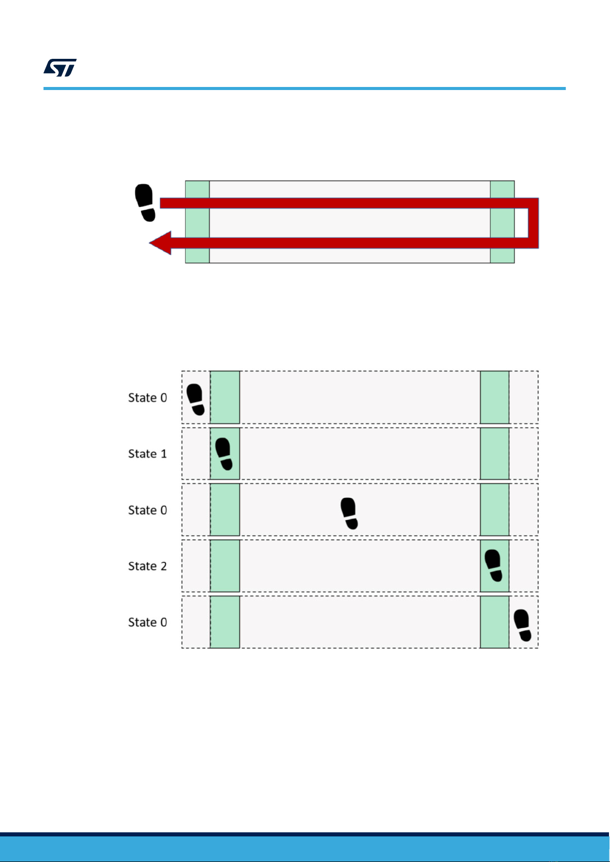
The above-mentioned demo purpose is to detect a specific foot/hand gesture and to inform a domain controller
via a CAN message that the successful detection event has occurred.
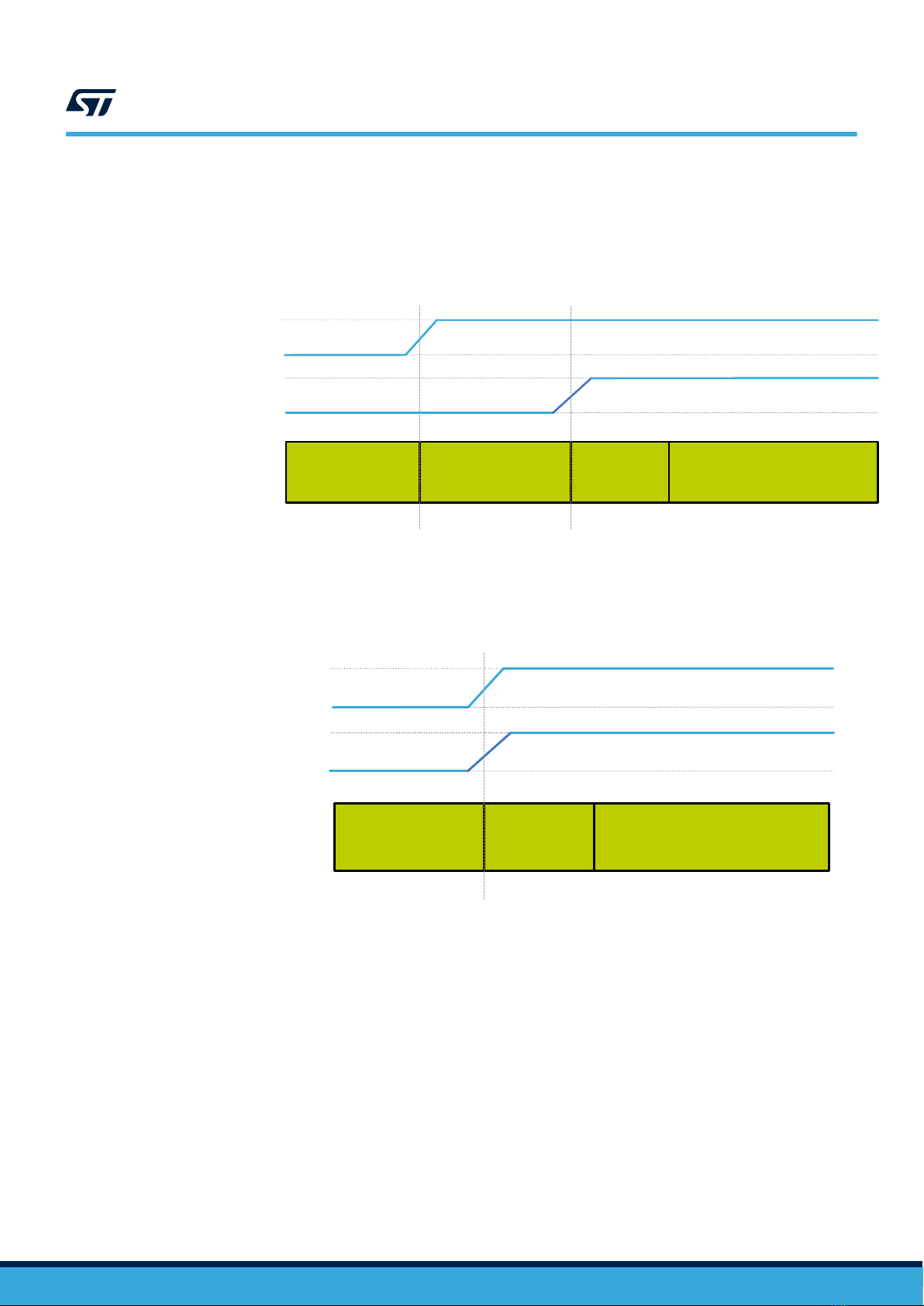
The gesture consists in a foot/hand movement from the left to the right and vice versa.
Figure 4. Gesture recognition pattern
The recognition process starts when the gesture crosses at least one of the photon beams emitted by the two ToF
sensors.
The algorithm implemented requires that the gesture has to be performed in one second maximum. If the gesture
is not detected, wait one second before repeating it. When the correct movement is detected, the two on-board
LEDs blink three times.
To work correctly, the demo requires the board to be placed at 132 mm height. Otherwise, the two sensors are
not properly configured during the power-up calibration phase. As soon as the board is turned on, and the system
is correctly initialized, the two on-board LEDs turn on. The two sensors detect the movement of the foot/hand for
distances between 0 and 120 mm. The demo can also receive external CAN messages to turn the ToF sensors
on/off. The detected_foot() is used to implement the gesture algorithm.
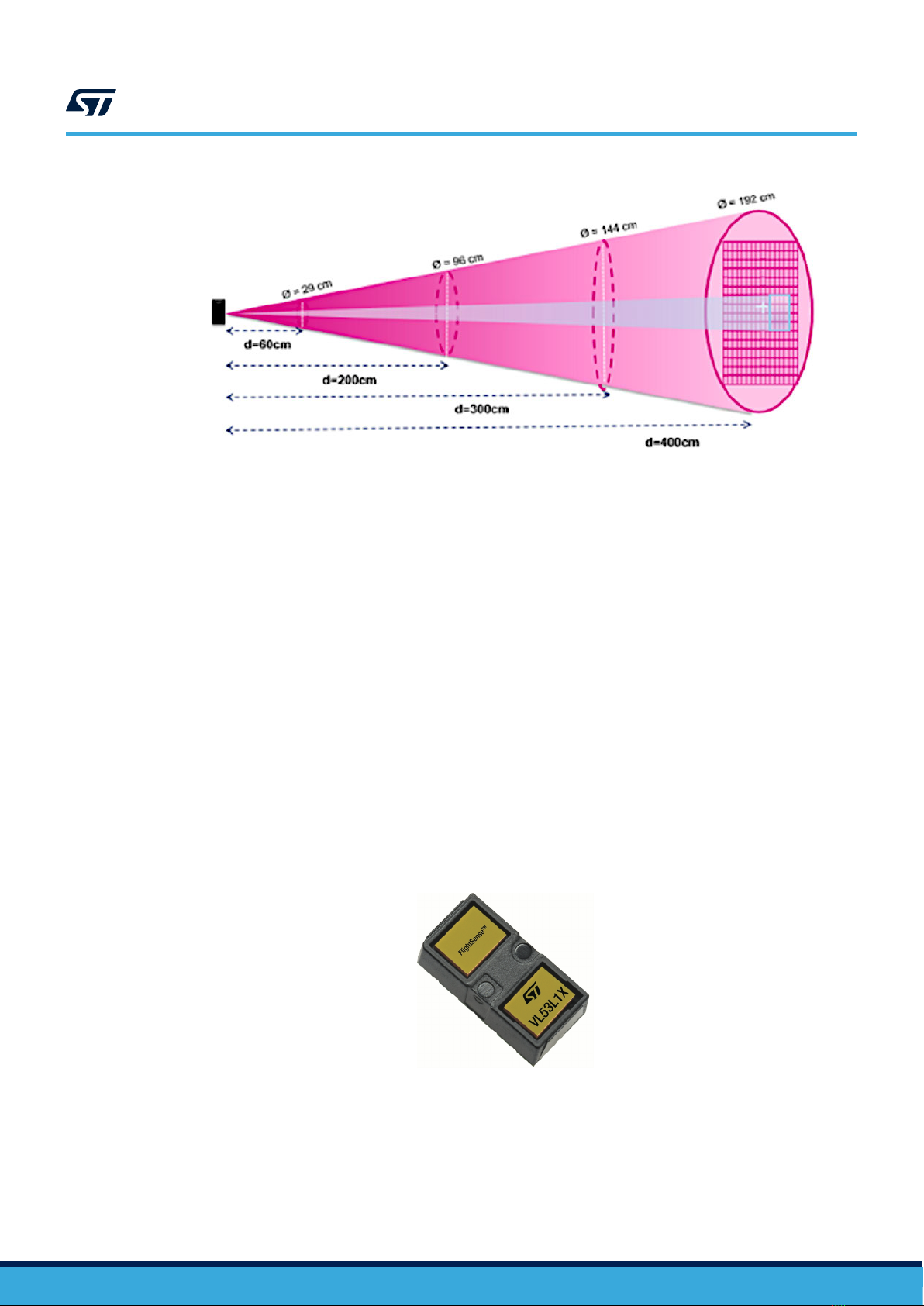
When performing the tests outdoor, ensure placing the AEK-SNS-2TOFM1 board as shown in the following figure,
to make the sensor photon beams fall within the car shadow cone.
Figure 5. Board placement
ToF
Car shadow
UM3006
Software overview
UM3006 - Rev 1 page 3/38

1.2.1 Gesture recognition
The gesture consists in crossing the detection base (that is, the distance between the two ToF sensors) in both
directions, as shown in the figure below.
Figure 6. Gesture on the detection base
The algorithm is based on the idea that the foot detection state can have one of the following values:
•0: not detected
• 1: detected by sensor 1 (left-hand side)
• 2: detected by sensor 2 (right-hand side)
Figure 7. Detection system states
A gesture can be represented through a sequence of states. The sequence that represents the gesture of the
figure above is: 0,1,0,2,0,2,0,1,0. The sequence 0,2,0,1,0,1,0,2,0 is also admitted as we want the gesture to start
in the opposite direction, too. The central zeros in the sequence are necessary because a complete crossing of
the detection base is desired. For example, the first admitted sequence is shown in the figure below.
UM3006
Software overview
UM3006 - Rev 1 page 4/38

Figure 8. Accepted sequence
The detect_foot () function, cyclically called by the microcontroller, implements the algorithm.
The foot detection functions can be divided in:
1. System State Detect that detects the state of the system:
– if sensor 1 detects an object, the state becomes 1
– if sensor 2 detects an object, the state becomes 2
– if there is no detection, the state becomes 0
– if both sensors detect something, the state becomes 3
The last value means that there is a fixed object under the trunk (for example, a stone).
2. State Sequence Update that updates the gesture sequence if the state changes.
3. State Sequence Check that compares the detected sequence with those admitted as soon as the
detected pattern reaches a length equal to the SEQ LEN. If there is a match, the function sets a, which is a
global variable representing the achieved foot detection, to 1.
4. System Reset: if the sequence reaches a length equal to the SEQ LEN and there is no match, or a RESET
TIME has elapsed, the system resets and restarts the detection mode.
UM3006
Software overview
UM3006 - Rev 1 page 5/38

2Basic concepts on FlightSense ToF sensors and their usage in
AutoDevKit
2.1 Overview of the FlightSense ToF sensor principle
The Time-of-Flight is a method for measuring the distance between a sensor and an object. It is based on the
time difference between the emission of a light signal and its return to the sensor, after being reflected by the
object.
Figure 9. ToF principle
According to the ToF principle, the sensors used in the AEK-SNS-2TOFM1 embed:
• an emitter that is a vertical cavity surface emitting laser (VCSEL);
• a receiver that is an array of single photon avalanche diodes (SPADs). The photons emitted by the laser
reflect on the target and trigger avalanches when coming back to the SPAD.
The ToF sensor also features a region of interest (ROI) that can be selected. It can be reduced from its nominal
27° field of view (FoV) to 15° with the only condition of having an array of at least 4x4 SPADs.
UM3006
Basic concepts on FlightSense ToF sensors and their usage in AutoDevKit
UM3006 - Rev 1 page 6/38

Figure 10. ToF sensor system FoV: receiver cone at 27°
The ROI selection is used to position the reduced sensing area at a selected place on the SPAD array to detect
and measure the distance of the specified area of interest of the external scene. Instead, the reduced FoV uses a
reduced number of SPADs for the ROI sensing area to limit the viewing angle of the sensor device.
For more information on the VL53L1X, refer to the datasheet, whereas, for more information about the
programmable region of interest (ROI), refer to AN5191.
2.2 VL53L1X
The VL53L1X is a state-of-the-art, Time-of-Flight (ToF), laser-ranging sensor, enhancing the ST FlightSense
product family. It is the fastest miniature ToF sensor on the market. It features an accurate ranging up to 4 m and
fast ranging frequency up to 50 Hz.
Housed in a miniature and reflowable package, it integrates:
• a SPAD receiving array;
• a 940 nm invisible Class1 laser emitter;
• physical infrared filters;
• optics to achieve the best ranging performance in various ambient lighting conditions with a range of cover
glass options.
Unlike conventional IR sensors, the VL53L1X uses ST latest generation ToF technology, which allows absolute
distance measurement independently of the target color and reflectance.
You can also program the size of the ROI on the receiving array, allowing the sensor FoV to be reduced.
Figure 11. VL53L1X ToF
UM3006
VL53L1X
UM3006 - Rev 1 page 7/38

2.2.1 ToF sensor characteristics
The AEK-SNS-2TOFM1 sensor characteristics are:
• a laser wavelength of 950 nm ± 30 nm;
• invisible laser (Class 1);
• invisible laser radiation;
• a maximum laser power emission of 25 mW.
2.2.2 Laser safety considerations
The AEK-SNS-2TOFM1 ToF sensors contain a laser emitter and the corresponding drive circuitry.
The laser output is designed to remain within Class 1 laser safety limits under all reasonable foreseeable
conditions, including single faults, in compliance with the IEC 60825-1:2014 (third edition).
The laser output remains within Class 1 limits as long as you use the STMicroelectronics recommended device
settings and respect the operating conditions specified in the data sheet.
The laser output power must not be increased and no optics should be used with the intention of focusing the
laser beam.
Figure 12. Class 1 laser product label
2.2.3 VL53L1X-SATEL industrial-grade ToF evaluation board
The AEK-SNS-2TOFM1 development is based on the hardware and software provided to evaluate the ToF
sensors. The evaluation board used is the VL53L1X-SATEL. For this board, we have already implemented an
AutoDevKit component named AEK_SNS_VL53L1X.
The demo software for the AEK-SNS-2TOFM1 has been developed by reusing the APIs already available for
the VL53L1X-SATEL. In turn, the VL53L1X-SATEL drivers have been imported from the STM32 drivers just by
customizing the hardware abstraction layer (HAL) calls for the SPC58 family microcontrollers.
The VL53L1X-SATEL breakout compact board can be used for easy integration.
Thanks to the voltage regulator and level shifters, this board can be used in any application with a 2.8 V to 5 V
supply.
UM3006
VL53L1X
UM3006 - Rev 1 page 8/38

Figure 13. VL53L1X-SATEL top and bottom views
The embedded VL53L1X ToF sensor uses the I²C protocol for communication.
The I²C bus on the VL53L1X has a maximum speed of 400 kbits/s and uses a default device address (0x52).
You can connect the VL53L1X-SATEL to an MCU board through different connection types, as shown in the figure
below.
Figure 14. VL53L1X-SATEL connection types
UM3006
VL53L1X
UM3006 - Rev 1 page 9/38

2.2.4 Power up and boot sequence
The ToF sensor has two different options for the power-up and boot sequence:
•Option 1: the XSHUT pin is connected and controlled from the host. This option optimizes the power
consumption as the sensor can be completely powered off when not used, and then woken-up again. The
hardware standby mode is defined as the period when the power supply is present and the XSHUT is low.
Figure 15. Power up and boot sequence
XShut
System state Power off HW standby SW standbyBoot
Power supply
•Option 2: the host does not control the XSHUT pin, which is tied to the power supply through a pull-up
resistor. When the XSHUT pin is not controlled, the power-up sequence starts as shown in the figure below.
In this case, the device goes automatically to software standby after boot, without entering the hardware
standby mode.
Figure 16. Power up and boot sequence with a pull-up resistor
XShut
System state Power off SW standbyBoot
Power supply
Note: The AEK_SNS_VL53L1X component uses option 1. This means that when more than one sensor is
used, each sensor XSHUT pin has to be connected. Then, the host turns the sensor on by using the
AEK_TOF_CONFIG procedure.
UM3006
VL53L1X
UM3006 - Rev 1 page 10/38

2.2.5 Ranging sequence
The following figure shows the combination of the driver commands and the system states.
Figure 17. Ranging sequence
Ranging
Power supply
Driver command Start
System state
SW standby Ranging
Ranging 1 Ranging 2
Init
Timing budget
Inter. measurement
XShut
GPIO1 (interrupt)
ranging
Get
rang. 1 Clear
int. Get
rang. 2
Stop
rang.
Inter. measurement SW standby
Timing budget
Inter. measurement period
The user can set the timing budget and the inter measurement period, using a dedicated driver function. The
timing budget is the ranging duration time, whereas the inter measurement period is the delay between two
ranging operations.
For more information on the VL53L1X industrial-grade ToF sensor, refer to the datasheet.
2.3 AutoDevKit software library for ToF sensors
The AEK_SNS_VL53L1X, which is a component that belongs to the AutoDevKit software version 1.6.1 (STSW-
AUTODEVKIT), supports all the drivers related to the VL53L1X.
The library is written in C and the target software is generated automatically according to the code generation and
pin allocation paradigm included in the AutoDevKit design flow.
Note: The AEK_SNS_VL53L1X has two different API options: ULD and FULL. These APIs have been adapted to be
used with the SPC58 line MCUs (SPC582Bxx, SPC584Bxx, SPC58ECxx).
The full driver (FULL) API includes the advanced sensor control functions. It is very complex and occupies a large
memory portion. For detailed information on the FULL library, refer to Full documentation.
The ultra-light drivers (ULD) API is user friendly and includes the basic functionalities. It is recommended for most
of the users. For detailed information on the ULD library, refer to ULD documentation..
Table 1. Main differences between VL53L1X FULL API and VL53L1X ULD API
Parameter VL53L1X FULL API VL53L1X ULD API
Code footprint in the flash memory 9 KB 2.3 KB
Number of files 35 4
Timing budget (ms) [20-500] [15, 20, 33, 50, 100, 200, 500]
Fast ranging (100 Hz) Yes No (66 Hz maximum)
Dynamic SPAD selection No Yes
As mentioned, the goal of the ToF sensors is to measure the distance. According to the library selected, the
measurement can be performed through different functions.
The figure below show the FULL and ULD library flowcharts, which describe the logic flow required to perform a
ranging.
UM3006
AutoDevKit software library for ToF sensors
UM3006 - Rev 1 page 11/38

Figure 18. FULL ranging flow
Figure 19. ULD ranging flow
UM3006
AutoDevKit software library for ToF sensors
UM3006 - Rev 1 page 12/38

ULD API functions:
1. VL53L1X_BootState
2. VL53L1X_SensorInit
3. Examples:
VL53L1X_SetTimingBudget
VL53L1X_SetOffset
4. VL53L1X_StartRanging
5. VL53L1X_CheckForDataReady
6. Trigger GPIO1 pin
7. VL53L1X_GetDistance
8. VL53L1X_ClearInterrupt
9. VL53L1X_StopRanging
2.4 How to access the AEK_SNS_VL53L1X1 API
To simplify API access, a struct(AEK_TOF_METHODS) method has been implemented in the AEK-SNS-
VL53L1X1 component developed in the AutoDevKit.
This struct is the key portion of the component. Its fields are function pointers to the selected API.
To implement this strategy, call the AEK_TOF_CONFIG function in the main function of the initialization section, as
follows:
int main(void)
{
componentsInit();
irqIsrEnable();
AEK_TOF_CONFIG();
.
.
The AEK_TOF_CONFIG function initializes the AEK_TOF_METHODS structure and the I²C addresses of the sensors
used.
Note: The AEK_TOF_DEV is an enumerator that identifies the sensor boards.
Once the AEK_SNS_VL53L1X1 component has been initialized, to access any function of the selected library, call
the AEK_TOF_METHODS function with the dot at the end. This makes the IDE show the list of the possible API
functions that can be used.
Figure 20. AEK_TOF_METHODS ULD
UM3006
How to access the AEK_SNS_VL53L1X1 API
UM3006 - Rev 1 page 13/38

Figure 21. AEK_TOF_METHODS FULL
UM3006
How to access the AEK_SNS_VL53L1X1 API
UM3006 - Rev 1 page 14/38

3AutoDevKit ecosystem
3.1 AutoDevKit overview
The application development employing the VL53L1X-SATEL industrial-grade ToF sensor board takes full
advantage of the AutoDevKit ecosystem, whose basic components are:
•SPC5-STUDIO integrated development environment (IDE)
•SPC5-UDESTK debugger
•STSW-AUTODEVKIT AutoDevKit software library
• AEK_SNS_VL53L1X driver
Refer to UM2623 for more information regarding SPC5-STUDIO and STSW-AUTODEVKIT.
3.2 SPC5-STUDIO
SPC5-STUDIO is an integrated development environment (IDE) based on Eclipse designed to assist the
development of embedded applications based on SPC5 Power Architecture 32-bit microcontrollers.
The package includes an application wizard to initiate projects with all the relevant components and key elements
required to generate the final application source code. It also contains straightforward software examples for each
MCU peripheral.
SPC5-STUDIO also features:
•the possibility of integrating other software products from the standard Eclipse marketplace
• free license GCC GNU C Compiler component
• support for industry-standard compilers
• support for multi-core microcontrollers
• PinMap editor to facilitate MCU pin configuration
Download the SPC5-UDESTK software to run and debug applications created with SPC5-STUDIO.
3.3 STSW-AUTODEVKIT
The STSW-AUTODEVKIT plug-in for Eclipse extends SPC5-STUDIO for automotive and transportation
applications.
STSW-AUTODEVKIT features:
• integrated hardware and software components, component compatibility checking, and MCU and peripheral
configuration tools
• the possibility of creating new system solutions from existing ones by adding or removing compatible
function boards
• new code can be generated immediately for any compatible MCU
• high-level application APIs to control each functional component, including the ones for the VL53L1X-SATEL
board
The GUI helps configure interfaces, including SPI, and can automatically manage all relevant pin allocation and
deallocation operations.
3.4 AEK_SNS_VL53L1X1 component
The STSW-AUTODEVKIT installation provides the AEK_SNS_VL53L1X drivers to facilitate the programming
phase. The AEK_SNS_VL53L1X component is supported starting from version 1.6.1. Thus, you need to update
your AutoDevKit installation if you have a previous version installed. After the proper installation, you can select
the component named [AEK-SNS-VL53L1X Component RLA].
Go to the configuration portion of the component, add an entry on the [Board List], selecting the sensor family,
I²C, and GPIO. Then, press the allocation button to make the AutoDevKit allocate all the needed pins on the MCU
board included in the project.
To check whether all the needed pins have been allocated, verify the PinMap editor. The pins allocated must be
two for the I²C protocol, several GPIO pins corresponding to the number of sensors selected, and an optional
interrupt dedicated GPIO pin if you have configured the interrupt option.
Through the [Board Viewer editor] you receive information on the sensor pins connected to the selected MCU
board.
UM3006
AutoDevKit ecosystem
UM3006 - Rev 1 page 15/38

Finally, fill the main() function and build the target application.
3.5 How to create a simple AEK-SNS-VL53L1X1 application
This example allows you to create an application with one sensor. The goal is to detect an object when it is within
a threshold that it is set between 50 and 150 millimeters. When the sensor detects the object, an interrupt is
triggered to inform the MCU that the measured data is ready to be processed.
We assume linking the sensor with the VL53L1X-SATEL and using the AEK-MCU-C4MLIT1 board.
Step 1. Create a new SPC5-STUDIO application for the SPC58EC series microcontroller and add the following
components:
– [SPC58ECxx Init Package Component RLA]
– [SPC58ECxx Low Level Drivers Component RLA]
–Note: Add these components immediately. Otherwise, the remaining components are not visible.
Step 2. Add the following additional components:
– [AutoDevKit Init Package Component]
– [AEK-SNS-VL53L1X1 Component RLA]
Figure 22. Adding [AEK_SNS_VL53L1X1 Component] in an SPC5-STUDIO project
1. SPC58ECxx Platform Component RLA
2. Open available component
3. AEK-SNS-VL53L1X1 Component RLA
Step 3. Select [AEK_SNS_VL53L1X1 Component RLA] to open the [Application Configuration] window.
Step 4. Select the option to configure all the features (I²C type, number of the sensors, library option, and
operating mode) from the drop-down menu.
UM3006
How to create a simple AEK-SNS-VL53L1X1 application
UM3006 - Rev 1 page 16/38

Step 5. Click on the [Allocation] button below the AEK-SNS-VL53L1X1 list. Then, click [OK] in the
confirmation window.
This operation delegates automatic pin allocation to the AutoDevKit.
Figure 23. AEK_SNS_VL53L1X1 component configuration
1. Selecting the [AEK_SNS_VL53L1X1 Component RLA]
2. Setting all the features
3. Clicking on the [Allocation] button
Step 6. Click on the PinMap editor icon to check that the required pins have been properly allocated:
–I²C SCL
– I²C SDA
– XSHUT GPIO
– EIRQ pin for the interrupt
Figure 24. AEK_SNS_VL53L1X1 PinMap window
Step 7. Close the PinMap editor and save the application.
Step 8. Generate and build the application using the appropriate icons in SPC5-STUDIO.
The project folder is then populated with the new files, including the main.c file and the components
folder with the AEK_SNS_VL53L1X1 drivers.
Step 9. Open the main.c file and include the AEK-SNS-VL53L1X1.h file.
UM3006
How to create a simple AEK-SNS-VL53L1X1 application
UM3006 - Rev 1 page 17/38

Step 10. Place the previous source code inside the main() function.
#include “components.h”
#include “AEK_SNS_VL53L1X1.h”
int main(void) {
VL53L1X_Result_t result;
volatile uint8_t irq_state;
/* Initialization of all the imported components in the order specified in the
application wizard. The function is generated automatically. */
componentsInit();
irqIsrEnable();
AEK_TOF_CONFIG();
/*Sensor set-up*/
AEK_TOF_METHODS.SensorInit(AEK_TOF_DEV0);
AEK_TOF_METHODS.SetDistanceMode(AEK_TOF_DEV0,2);
AEK_TOF_METHODS.SetTimingBudgetInMs(AEK_TOF_DEV0,20);
AEK_TOF_METHODS.SetInterMeasurementInMs(AEK_TOF_DEV0,54);
AEK_TOF_METHODS.SetDistanceThreshold(AEK_TOF_DEV0,50,150,3,1);
AEK_TOF_METHODS.StartRanging(AEK_TOF_DEV0);
/* Application main loop. */
for( ; ; )
{
AEK_TOF_METHODS.GetIRQSensorState(AEK_TOF_DEV0,&irq_state);
if(irq_state == 1)
{
AEK_TOF_METHODS.SetIRQSensorState(AEK_TOF_DEV0);
AEK_TOF_METHODS.GetResult(AEK_TOF_DEV0,&result);
AEK_TOF_METHODS.ClearInterrupt(AEK_TOF_DEV0);
}
}
}
Step 11. Save, generate, and compile the application.
Step 12. Open the [Board View Editor] provided by the AutoDevKit.
This editor provides a graphical point-to-point guide on how to wire the boards.
Step 13. Connect the AEK-MCU-C4MLIT1 to a USB port on your PC using a mini-USB to USB cable.
Step 14. Launch SPC5-UDESTK, open the debug folder, and select the debug.wsx file in the "AEK-MCU
C4MLIT1– Application/UDE" folder.
Step 15. Run and debug your code.
Note: The AEK-MCU-C4MLIT1 has several jumpers to activate specific peripherals. These jumpers
influence the behavior of the connected pins. AutoDevKit automatic allocation is not able to
understand if a specific pin has been allocated through a jumper configuration. In case of conflicts,
force a different pin from the PinMap editor. Ensure naming the pin with the same name defined
through the AutoDevKit automatic allocation.
3.6 Available demos for AEK-SNS-VL53L1X1
There are four different demos with specific features provided with the AEK-SNS-VL53L1X1 component:
1. SPC584Bxx_RLA AEK_SNS_VL53L1X1 - ULD Threshold Demo - Test Application
2. SPC58ECxx_RLA AEK_SNS_VL53L1X1 - FULL Demo I2C SW - Test Application
3. SPC58ECxx_RLA AEK_SNS_VL53L1X1 - FULL Demo Double Sensor Ranging - Test Application
4. SPC58ECxx_RLA AEK_SNS_VL53L1X1 – ULD Demo Set Threshold - Test Application
3.6.1 SPC584Bxx_RLA AEK_SNS_VL53L1X1 - ULD Threshold Demo - Test Application
In this demo, we use the ULD API.
We set the threshold in a range between 50 and 150 millimeters, so the sensor can detect all the objects in this
range.
The main APIs used are:
•AEK_TOF_CONFIG(): this function must be called first. It configures one or more XSHUT pins, turns the
sensors on, and configures the sensors I²C slave address.
UM3006
Available demos for AEK-SNS-VL53L1X1
UM3006 - Rev 1 page 18/38

•SensorInit: loads the 135 bytes default values to initialize the sensor.
•SetDistanceMode: programs the distance mode (1 = short, 2 = long (default)).
•SetTimingBudgetInMs: sets the timing budget.
•SetInterMeasurementInMs: sets the intermeasurement period.
•SetDistanceThreshold: programs the threshold detection mode.
•StartRanging(AEK_TOF_DEV0): starts the ranging distance operation.
•GetIRQSensorState(AEK_TOF_DEV0,&irq_state): returns the interrupt state.
•SetIRQSensorState(AEK_TOF_DEV0): sets the interrupt state to 0.
•GetResult(AEK_TOF_DEV0,&result): returns ranging data.
•ClearInterrupt(AEK_TOF_DEV0): clears the interrupt to enable the next ranging.
Note: The SPC58ECxx_RLA AEK_SNS_VL53L1X1–ULD Demo Set Threshold - Test Application has the same
settings but uses the SPC58EC Chorus 4 MB flash memory board.
3.6.2 SPC58ECxx_RLA AEK_SNS_VL53L1X1 - FULL Demo Double Sensor Ranging - Test Application
In this demo, we use two AEK-SNS-2TOFM1 boards in polling mode with the FULL library.
The boards have both the same settings. In this way, we can detect the objects in two different areas.
The main APIs used are:
•AEK_TOF_CONFIG(): this function must be called first. It configures one or more XSHUT pins, turns the
sensors on, and configures the sensors I²C slave address.
•DataInit(AEK_TOF_DEV0): performs device initialization.
•StaticInit(AEK_TOF_DEV0): loads the specific device settings.
•SetDistanceMode(AEK_TOF_DEV0,VL53L1_DISTANCEMODE_SHORT): sets the distance mode to be
used for the next ranging.
•SetMeasurementTimingBudgetMicroSeconds(AEK_TOF_DEV0,50000): sets the timing budget, that
is, the time required by the sensor to measure a range.
•SetInterMeasurementPeriodMilliSeconds(AEK_TOF_DEV0,500): sets the intermeasurement
period, that is, the period time before resuming the next ranging measurement.
•StartMeasurement(AEK_TOF_DEV0): this function must be called to start a measurement.
•WaitMeasurementDataReady(i): polls on the device interrupt status until ranging data are ready.
•GetRangingMeasurementData(i,&result): returns the ranging data.
•ClearInterruptAndStartMeasurement(i): starts a new measurement.
Note: The SPC58ECxx_RLA AEK_SNS_VL53L1X1 - FULL Demo I2C SW - Test Application has the same settings but
uses the I²C software version.
UM3006
Available demos for AEK-SNS-VL53L1X1
UM3006 - Rev 1 page 19/38

3.7 How to upload the demos for AEK-SNS-2TOFM1
Follow the procedure below to import the demos into SPC5-STUDIO.
Step 1. Select [Import samples from application library] from the [Common tasks] panel.
An import application wizard appears.
Step 2. Insert the appropriate product MCU family details.
Figure 25. Demo upload
Step 3. Select the desired application from the library.
Step 4. Click on the [Finish] button.
UM3006
How to upload the demos for AEK-SNS-2TOFM1
UM3006 - Rev 1 page 20/38
Table of contents
Other ST Motherboard manuals

ST
ST UM2711 User manual

ST
ST STEVAL-L99615C User manual

ST
ST STEVAL-MKI109V2 User manual

ST
ST SPC58NHADPT386S User manual

ST
ST SPC572LADPT80S User manual

ST
ST NUCLEO-F207ZG User manual

ST
ST STA333ML Installation and operating instructions

ST
ST ST7LIT15BY0 User manual

ST
ST STEVAL-SP1ML915 User manual

ST
ST STEVAL-ILL059V1 User manual