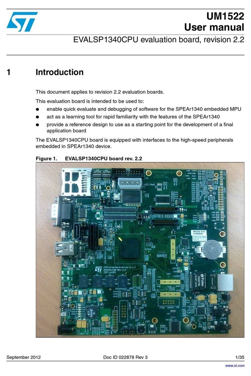
ST STM32100E-EVAL User manual

March 2011 Doc ID 018466 Rev 1 1/49
UM1055
User manual
STM32100E-EVAL evaluation board
Introduction
The STM32100E-EVAL evaluation board is designed as a complete development platform
for the STMicroelectronics ARM®Cortex-M3 core-based STM32F100 microcontroller with
HDMI CEC connection, FSMC (Flexible Static Memory Controller), two I2C, three SPI, five
USART, 32 Kbytes of internal SRAM, 512 Kbytes of internal Flash memory and JTAG and
SWD debugging/programming support.
The full range of hardware features on the board helps you evaluate all peripherals
(HDMI CEC, SRAM, motor control, LCD, MicroSD card, serial Flash, EEPROM, temperature
sensor, speaker, IrDA, RS-232, RS-485… etc.) and develop your own applications.
Extension headers facilitate the connection of a daughterboard or wrapping board for your
specific applications.
A ST-LINK/V2 is integrated on the board as an embedded debugger and programmer for the
STM32F100 MCU.
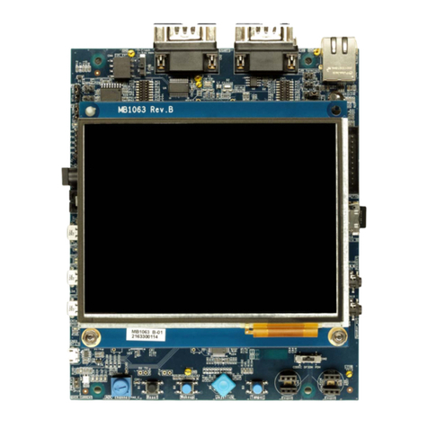
Figure 1. STM32100E-EVAL evaluation board
www.st.com
This datasheet has been downloaded fromhttp://www.digchip.com at this page

Contents UM1055
2/49 Doc ID 018466 Rev 1
Contents
1 Overview . . . . . . . . . . . . . . . . . . . . . . . . . . . . . . . . . . . . . . . . . . . . . . . . . . 4
1.1 Features . . . . . . . . . . . . . . . . . . . . . . . . . . . . . . . . . . . . . . . . . . . . . . . . . . . 4
1.2 Demonstration software . . . . . . . . . . . . . . . . . . . . . . . . . . . . . . . . . . . . . . . 4
1.3 Order code . . . . . . . . . . . . . . . . . . . . . . . . . . . . . . . . . . . . . . . . . . . . . . . . . 4
2 Hardware layout and configuration . . . . . . . . . . . . . . . . . . . . . . . . . . . . . 5
2.1 Development and debug support . . . . . . . . . . . . . . . . . . . . . . . . . . . . . . . . 7
2.2 Power supply . . . . . . . . . . . . . . . . . . . . . . . . . . . . . . . . . . . . . . . . . . . . . . . 7
2.3 Boot option . . . . . . . . . . . . . . . . . . . . . . . . . . . . . . . . . . . . . . . . . . . . . . . . . 8
2.4 Clock source . . . . . . . . . . . . . . . . . . . . . . . . . . . . . . . . . . . . . . . . . . . . . . . . 9
2.5 Reset source . . . . . . . . . . . . . . . . . . . . . . . . . . . . . . . . . . . . . . . . . . . . . . . 9
2.6 Audio . . . . . . . . . . . . . . . . . . . . . . . . . . . . . . . . . . . . . . . . . . . . . . . . . . . . 10
2.7 EEPROM . . . . . . . . . . . . . . . . . . . . . . . . . . . . . . . . . . . . . . . . . . . . . . . . . 10
2.8 IrDA . . . . . . . . . . . . . . . . . . . . . . . . . . . . . . . . . . . . . . . . . . . . . . . . . . . . . 10
2.9 Motor control . . . . . . . . . . . . . . . . . . . . . . . . . . . . . . . . . . . . . . . . . . . . . . 11
2.10 MicroSD card . . . . . . . . . . . . . . . . . . . . . . . . . . . . . . . . . . . . . . . . . . . . . . 12
2.11 Analog input . . . . . . . . . . . . . . . . . . . . . . . . . . . . . . . . . . . . . . . . . . . . . . . 12
2.12 SRAM . . . . . . . . . . . . . . . . . . . . . . . . . . . . . . . . . . . . . . . . . . . . . . . . . . . . 12
2.13 Serial Flash . . . . . . . . . . . . . . . . . . . . . . . . . . . . . . . . . . . . . . . . . . . . . . . 12
2.14 Temperature sensor . . . . . . . . . . . . . . . . . . . . . . . . . . . . . . . . . . . . . . . . . 12
2.15 Display and input devices . . . . . . . . . . . . . . . . . . . . . . . . . . . . . . . . . . . . . 13
2.16 HDMI CEC . . . . . . . . . . . . . . . . . . . . . . . . . . . . . . . . . . . . . . . . . . . . . . . . 13
2.17 IR receiver . . . . . . . . . . . . . . . . . . . . . . . . . . . . . . . . . . . . . . . . . . . . . . . . 13
2.18 RS-232 communication . . . . . . . . . . . . . . . . . . . . . . . . . . . . . . . . . . . . . . 13
2.19 RS-485 communication . . . . . . . . . . . . . . . . . . . . . . . . . . . . . . . . . . . . . . 14
3 Connectors . . . . . . . . . . . . . . . . . . . . . . . . . . . . . . . . . . . . . . . . . . . . . . . 15
3.1 Motor control connector CN1 . . . . . . . . . . . . . . . . . . . . . . . . . . . . . . . . . . 15
3.2 HDMI connectors CN2 and CN3 . . . . . . . . . . . . . . . . . . . . . . . . . . . . . . . 16
3.3 Analog input connector CN4 . . . . . . . . . . . . . . . . . . . . . . . . . . . . . . . . . . 16
3.4 RS-232 connector CN5 with RTS/CTS handshake support . . . . . . . . . . . 17

UM1055 Contents
Doc ID 018466 Rev 1 3/49
3.5 RS-232 with ISP support and RS-485 connector CN10 . . . . . . . . . . . . . . 17
3.6 MicroSD connector CN6 . . . . . . . . . . . . . . . . . . . . . . . . . . . . . . . . . . . . . . 18
3.7 JTAG debugging connector CN7 . . . . . . . . . . . . . . . . . . . . . . . . . . . . . . . 18
3.8 Daughterboard extension connectors CN8 and CN9 . . . . . . . . . . . . . . . . 19
3.9 Audio jack CN11 . . . . . . . . . . . . . . . . . . . . . . . . . . . . . . . . . . . . . . . . . . . . 24
3.10 ST-LINK/V2 connector CN13 (USB connector) . . . . . . . . . . . . . . . . . . . . 24
3.11 ST-LINK/V2 programming connector CN12 (reserved connector) . . . . . . 24
3.12 Power connector CN14 . . . . . . . . . . . . . . . . . . . . . . . . . . . . . . . . . . . . . . 25
4 Schematics . . . . . . . . . . . . . . . . . . . . . . . . . . . . . . . . . . . . . . . . . . . . . . . 26
Appendix A STM32100E-EVAL pinout . . . . . . . . . . . . . . . . . . . . . . . . . . . . . . . . . 43
5 Revision history . . . . . . . . . . . . . . . . . . . . . . . . . . . . . . . . . . . . . . . . . . . 48

Overview UM1055
4/49 Doc ID 018466 Rev 1
1 Overview
1.1 Features
●Three 5V power supply options:
–Powerjack
– ST-LINK/V2 connector
– Daughterboard
●Boot from user Flash, system memory or SRAM
●1 Gbyte (or more) MicroSD card
●16 Mbytes of serial Flash memory
●2 Mbytes of SRAM
●8 Kbytes of EEPROM
●I2C/SMBus compatible serial interface temperature sensor
●2-channel RS-232 communication interface with RTS/CTS handshake support on one
channel
●1-channel RS-485 communication interface sharing the USART1 connector
●IrDA transceiver
●IR receiver
●Inductor motor control connector
●JTAG and SWD debug support
●3.2" TFT color LCD with touch screen
●Joystick with 4-direction control and selector
●Reset, wakeup, tamper and user buttons
●Speaker
●4 LEDs
●RTC with backup battery
●Extension connector for daughterboard or wrapping board
●Embedded ST-LINK/V2 debugger and programmer
●HDMI (High-Definition Multimedia Interface) with Consumer Electronics Control (CEC)
connection
1.2 Demonstration software
Demonstration software is preloaded on board Flash memory for easy demonstration of the
device peripherals in standalone mode. For more information and to download the latest
version available, please refer to STM32100E-EVAL demonstration software available on
the web: www.st.com/mcu.
1.3 Order code
To order the STM32F100ZET6 MCU evaluation board, use the order code
STM32100E-EVAL.

UM1055 Hardware layout and configuration
Doc ID 018466 Rev 1 5/49
2 Hardware layout and configuration
The STM32100E-EVAL evaluation board is designed around the STM32F100ZET6 (144-pin
LQFP package). The hardware block diagram Figure 2 illustrates the connection between
STM32F100ZET6 and peripherals (LCD, SRAM, IR receiver, SPI Flash, USART, IrDA,
speaker, HDMI CEC, temperature sensor, MicroSD card, motor control and embedded
ST-LINK/V2) and Figure 3 will help you locate these features on the actual evaluation board.
Figure 2. Hardware block diagram
34-&:%4
23
TRANSCEIVER
)R$!
TRANSCEIVER
-ICRO3$
CARD
3PEAKER
!MPLIFIER
".#
CONNECTOR
,%$S
0OTENTIOMETER
53!24
$"CONNECTOR
$!#
'0)/
)#
53!24
4EMPERATURE
3ENSOR
*4!'
*OYSTICK
!$#
%MBEDDED
34 ,).+6
53"4YPE"
CONNECTOR
"UTTONS
-OTOR#ONTROL
CONNECTOR -# *4!'4RACE
CONNECTOR
53!24
$"CONNECTOR
30)
53!24
23
TRANSCEIVER
53!24
3ERIAL&LASH
#%#
)#
($-)
CONNECTOR
($-)
CONNECTOR
%%02/-
,#$4OUCH
SCREEN
53!24 23
TRANSCEIVER
)2RECEIVER 4)-?#(
&3-#
-"YTE
32!-
4&4
,#$
34-&:%4
TRANSCEIVER
)R$!
TRANSCEIVER
-ICRO3$
CARD
3PEAKER
!MPLIFIER
".#
CONNECTOR
,%$S
0OTENTIOMETER
53!24
$"CONNECTOR
$!#
'0)/
)#
*4!'
*OYSTICK
!$#
%MBEDDED
34 ,).+6
53"4YPE"
CONNECTOR
"UTTONS
-OTOR#ONTROL
CONNECTOR -# *4!'4RACE
CONNECTOR
53!24
$"CONNECTOR
30)
53!24
TRANSCEIVER
3ERIAL&LASH
#%#
)#
($-)
CONNECTOR
($-)
CONNECTOR
%%02/-
,#$4OUCH
SCREEN
53!24 TRANSCEIVER
)2RECEIVER 4)-?#(
&3-#
-"YTE
32!-
4&4
,#$
6REGULATOR
%XTENSION
CONNECTORFOR
'0)/S
23
23
23
-36
30)

Hardware layout and configuration UM1055
6/49 Doc ID 018466 Rev 1
Figure 3. STM32100E-EVAL Evaluation board layout
#.#.
%XTENSIONHEADER
5
)2RECEIVER
#.
-ICRO3$CARD
5
34-&:%4
#.
#.
53!2423
#.
!UDIO*ACK
#.
0OWERJACK
"
2ESET "
7AKEUP
"
4AMPER 5
*OYSTICK
"
+EY
5
)R$!
26
0OTENTIOMETER
#.
4&4,#$
#.
*4!'
34,).+6
#.
".#
#.
($-)CONNECTOR
#.
($-)CONNECTOR
#.
-OTORCONTROL
5
32!-
-36
53!24
#.
,%$
#/-

UM1055 Hardware layout and configuration
Doc ID 018466 Rev 1 7/49
2.1 Development and debug support
Version 2 of the ST-LINK, known as ST-LINK/V2, is embedded on the board. This tool allows
program loading and debugging of the STM32F using the JTAG or SWD interface
Third-party debug tools are also supported by using the JTAG connector (CN7).
A specific driver needs to be installed on your PC for communication with the embedded
ST-LINK/V2. The InstallShield package ST-LINK_V2_USBdriver.exe is available from the ST
website. To download and install this driver, please refer to Software and development
tools page for STM32F family available on www.st.com.
Connect the embedded ST-LINK/V2 to the PC via a standard USB cable from connector
CN13. The bi-color LED LD5 (COM in Figure 3) indicates the status of the communication
as follows:
●Slow blinking Red/Off: At power-on before USB initialization
●Fast blinking Red/Off: After the first correct communication between PC and STLink/V2
(enumeration)
●Red LED On: When initialization between PC and ST-LINK/V2 is successfully finished
●Green LED On: After successful target communication initialization
●Blinking Red/Green: During communication with target
●Green On: Communication finished and OK
●Orange On: Communication failure
Note: Note: It is possible to power the board via CN13 (embedded ST-LINK/V2 USB connector)
even if an external tool is connected to CN7 (external JTAG and SWD).
2.2 Power supply
STM32100E-EVAL evaluation board is designed to be powered by a 5 V DC power supply
and to be protected by PolyZen U18 from damage caused by overvoltage and overcurrent
fault conditions. It is possible to configure the evaluation board to use any of following three
power supply sources:
●5V DC power adapter connected to CN14, the Power Jack on the board (Power Supply
Unit (PSU) in Figure 3, JP13 jumper description in Ta bl e 1 ).
●5V DC power with 500mA limitation from CN13, the ST-LINK/V2 type-B USB connector
(STlk in Figure 3, JP13 jumper description in Table 1).
●5V DC power from both CN8 and CN9, the extension connector for daughterboard
(DTB for Daughterboard in Figure 3, JP13 jumper description in Ta bl e 1 ).
The power supply is configured by setting the related jumpers JP13, JP1 and JP10 as
described in Ta b l e 1 .
Hardware layout and configuration UM1055
8/49 Doc ID 018466 Rev 1
The LED LD6 is lit when the STM32100E-EVAL evaluation board is powered by the 5 V
correctly.
Note: The recommended AC220V to DC5V power adapter is the PSU-5V2A. It is not included with
the board but can be ordered from ST as a separate item. You can also use another
equivalent 5V power adapter (polarity compatible with CN14) to power STM32100E-EVAL
board via the CN14 power jack on the board. To order the recommended power supply, use
the order code: PSU-5V2A.
2.3 Boot option
The STM32100E-EVAL evaluation board is able to boot from:
●Embedded user Flash
●System memory with boot loader for ISP
●Embedded SRAM for debugging
Table 1. Power related jumpers
Jumper Description Jumper setting
JP13
(selects one of
the three possible
power supply
resources)
For power supply jack (CN14) to the STM32100E-EVAL only,
JP13 is set as shown to the right:
For power supply from the daughterboard connectors (CN8
and CN9) to STM32100E-EVAL only, JP13 is set as shown to
the right:
For power supply from ST-LINK/V2 USB connector (CN13) to
STM32100E-EVAL only, JP13 is set as shown to the right:
(Default setting)
For power supply from power supply jack (CN14) to both
STM32100E-EVAL and daughterboard connected on CN8 and
CN9, JP13 is set as shown to the right:
(daughter board must have not its own powersupply
connected)
JP1
Vbat is connected to +3.3V power when JP1 is set as shown to
the right:
(Default setting)
Vbat is connected to battery when JP1 is set as shown to the
right:
JP10 Enables consumption measurements of both VDD and VDDA.
Default setting: Fitted
035
$4"
53"
035
$4"
34LK
035
$4"
53"
035
$4"
34LK
035
$4"
53"
035
$4"
34LK
035
$4"
53"
035
$4"
34LK
321
321

UM1055 Hardware layout and configuration
Doc ID 018466 Rev 1 9/49
The boot option is configured by setting switch SW1 and SW2.
2.4 Clock source
Two clock sources are available on STM32100E-EVAL evaluation board for
STM32F100ZET6 microcontroller:
●X2, 32 kHz crystal for embedded RTC
●X1, 8 MHz Crystal with socket for STM32F100ZET6 Microcontroller, it can be removed
from its socket when internal RC clock is used.
2.5 Reset source
The reset signal of STM32100E-EVAL evaluation board is active low and the reset sources
include:
●Reset button B1
●Debugging tools from JTAG connector CN7
●Daughterboard from CN9
●Embedded ST-LINK/V2
●Bootloader_Reset from RS-232 connector CN10
Table 2. Boot related switches and jumper
Switch Boot source Switch
configuration
SW1
SW2
STM32100E-EVAL boot from User Flash when BOOT0 is set as shown
to the right:
BOOT1 is don’t care in this configuration.
(Default setting)
STM32100E-EVAL boot from Embedded SRAM when BOOT0 and
BOOT1 are set as shown to the right:
STM32100E-EVAL boot from System Memory when BOOT0 and
BOOT1 are set as shown to the right:
JP8
The BOOT0 pin of STM32F100ZET6 is connected to RS-232 connector
CN10 pin 6 (DSR) for ISP support when JP8 is closed. This
configuration is used for bootloader application only.
(Default Setting: Not fitted)
Table 3. RTC related solder bridges
Solder bridge Description
SB5, SB6
PC14 and PC15 are connected to extension connector CN8 when solder
bridges SB5 and SB6 are closed.
Default Setting: Not fitted

Hardware layout and configuration UM1055
10/49 Doc ID 018466 Rev 1
2.6 Audio
STM32100E-EVAL evaluation board supports playback based on a speaker on the board.
Two channels DAC of STM32F100ZET6 are connected to audio amplifier TS4956EIJT
which drive both speaker and stereo audio jack output. The audio volume can be adjusted
by configuration of audio amplifier through I2C interface.
Note: Channel DAC1 is shared by audio and BNC while channel DAC2 is shared by audio and
serial Flash on the board.
2.7 EEPROM
The EEPROM M24C64-WMN6TP connected to I2C2 of STM32F100ZET6 is available on
the board. Its address can be changed by setting solder bridge SB10.
2.8 IrDA
IrDA communication is supported by IrDA transceiver U16 connected to USART4 of
STM32F100ZET6. IrDA can be enabled or disabled by setting PA11.
Table 4. Reset related jumpers
Jumper Description
JP7
Bootloader_Reset signal from RS-232 connector CN10 pin 1 (DCD) is
connected to RESET# of STM32F100ZET6 when JP7 is closed. This
configuration is used for bootloader application only.
Default Setting: Not fitted.
Table 5. Audio related jumpers
Jumper Description
JP15
The I/O pin PA5 is connected to Audio DAC as DAC2 when JP15 is closed.
JP15 must be kept open for connection to serial flash as Flash_SCK.
Default setting: Not fitted
Table 6. EEPROM related jumper and solder bridge
Jumper Description
JP14 The EEPROM write operations are disabled when JP14 is open.
Default Setting: Fitted
SB10
The device address of EEPROM is 0xA0 when SB10 is open and 0xA2
when SB10 is closed.
Default Setting: Not fitted

UM1055 Hardware layout and configuration
Doc ID 018466 Rev 1 11/49
2.9 Motor control
The STM32100E-EVAL evaluation board supports an induction motor control via a 34-pin
connector. Connector CN1 provides all required control and feedback signals to and from
the motor power driving board. Available signals on this connector include emergency stop,
motor speed, 3-phase motor current, bus voltage, heatsink temperature coming from the
motor driving board and 6 channels of PWM control signal going to the motor driving circuit.
Special motor current sampling operation is enabled by setting jumper JP12.
Table 7. Motor control related jumpers
Jumper Description
JP12
The special motor current sampling operation is enabled when
JP12 is fitted (PD2 connected to PB4). The I/O pins PD2 and PB4
are disconnected and can be used by daughterboard when JP12
is NOT fitted.
Default setting: Not fitted
JP2
JP2 must be open when encoder signal is from pin 31 of motor
control connector CN1. JP2 must be closed when the analog
signal is from pin31 of CN1 for special motor.
Default setting: Not fitted
JP3
PA6 is connected to motor control connector CN1 as
MC_EmergencySTOP when JP3 is closed. JP3 must be kept on
open for serial Flash operation.
Default setting: Not fitted
JP4
PA0 is connected to RS-232 transceiver U5 as USART2_CTS
when JP4 is set as shown to the right:
(Default setting)
PA0 is connected to motor control connector CN1 as MC_EnA
when JP4 is set as shown to the right:
JP5
PA10 is connected to motor control connector CN1 as MC_WH
when JP5 is set as shown to the right:
PA10 is connected to USART1_RX when JP4 JP5 is set as shown
to the right: (Default setting)
JP9
PD2 is used as MC_PFCsync2 output on motor control connector
CN1 when JP9 is open. PD2 is used as USART5_RX input when
JP9 is closed.
Default setting: Fitted
JP11
PB12 is used as MC_NTC on motor control connector CN1 when
JP11 is open. PB12 is used as temperature interrupt input when
JP11 is closed. JP11 must be kept closed for
TemperatureSensor_INT operation.
Default setting: Fitted
321
321
321
321

Hardware layout and configuration UM1055
12/49 Doc ID 018466 Rev 1
2.10 MicroSD card
The 1 Gbyte (or more) MicroSD card connected to SPI2 of STM32F100ZET6 is available on
the board. MicroSD card chip select is managed by standard I/O port PG6 while MicroSD
card detect signal is managed by I/O port PF11.
2.11 Analog input
One BNC connector CN4 is connected to PA4 of STM32F100ZET6 as external analog input
or DAC output. The 50 ohm terminal resister can be enabled by closing of solder bridge
SB2. A low pass filter can be implemented for BNC connector by replacing of R49 and C45
by ADC input or replacing R48 and C45 for DAC output with the right value of the resister
and capacitor as presented in the end user’s application.
There are also 2 analog signals available on the board:
●10K ohm potentiometer RV1 connected to PC4.
●External ADC input which can be connected to TP1 (AIN+) and TP2 (AIN-), R51 should
be removed to avoid noise.
2.12 SRAM
The 2 Mbyte SRAM (IS61WV102416BLL-10MLI) is connected to Bank 2 of FSMC of
STM32F100ZET6 on the board.
2.13 Serial Flash
A 128 Mbit serial Flash memory connected to SPI1 of STM32F100ZET6, serial Flash chip
select is managed by standard I/O port PE6.
Note: JP3 must be kept open for serial Flash operation. Please refer to Table 7 for details.
2.14 Temperature sensor
One I2C interface temperature sensor STLM75 (–55°C to +125°C) connected to I2C2 of
STM32F100ZET6 is available on the board. Its address can be changed by setting of solder
bridge SB8.
Note: JP11 must be closed for temperatureSensor_INT operation. Please refer to Ta b l e 7 for details.
Table 8. Temperature Sensor Related Solder bridges
Jumper Description
SB8
Temperature sensor device address is 0x90 when SB8 is open and 0x92
when SB8 is closed.
Default Setting: Not fitted

UM1055 Hardware layout and configuration
Doc ID 018466 Rev 1 13/49
2.15 Display and input devices
The 3.2” TFT color LCD connected to Bank 3 (FSMC) of STM32F100ZET6 and 4 general
purpose LEDs (LD1,2,3,4) are available as display devices. The touch screen is supported
on the TFT LCD by I/O port expander STMPE811QTR which is connected via I2C bus to the
microcontroller. A 4-direction joystick with selection key, general purpose button (B4),
wakeup button (B2) and tamper detection button (B3) are available as input devices.
2.16 HDMI CEC
Two HDMI connectors CN2 and CN3 are available on STM32100E-EVAL board. The signals
CEC, SCL, SDA and HPD are supported and connected to STM32F100ZET6 through
HDMI2C1-5DIJ, the ST full integrated ESD protection, level-shifting device and signal
booster for control links of HDMI 1.3 transmitter.
2.17 IR receiver
The IR receiver TSOP34836 is connected to PC6 of STM32F100ZET6 on the board.
2.18 RS-232 communication
Two D-type 9-pin connectors are available on STM32100E-EVAL evaluation board:
●CN10 (USART1) connector is connected to RS-232 transceiver U7 with
Bootloader_Reset and Bootloader_BOOT0 support for ISP
●CN5 (USART2) connector with RTS/CTS handshake signal support is connected to
RS-232 transceiver U5
Table 9. Touch screen related solder bridge and jumper
Jumper Description
SB9
The device address of I/O expander U19 is 0x82 when SB9 is open and
0x88 when SB9 is closed.
Default Setting: Not fitted
Table 10. HDMI CEC Related solder bridge and Jumper
Jumper Description
SB1
The +5V power pin of HDMI connectors CN2 and CN3 is
connected to 5V power on STM32100E-EVAL board when SB1 is
closed.
Defult Status: Open
JP6
PB7 is connected to HDMI level shifter U2 as I2C1_SDA when JP6
is set as shown to the right:
(Default setting)
Configuration not used:
321
321

Hardware layout and configuration UM1055
14/49 Doc ID 018466 Rev 1
Note: Jumper JP4 must be fitted on pins 2-3 for USART2 operations and jumper JP5 must be
fitted on pins 1-2 for for USART1 operations. Please refer to Ta bl e 7 for more details.
2.19 RS-485 communication
The RS-485 communication on USART5 is supported by RS-485 transceiver ST485ABDR
and connected to pin4 and pin 9 of D-type 9-pin connector CN10 (shared with USART1).
Note: Jumper JP9 must be fitted for RS-485 operations. Please refer to Ta b l e 7 for more details.
Table 11. RS-485 related solder bridges
Solder bridge Description
SB3, SB4
The external fail-safe biasing are enabled when solder bridges SB3 and
SB4 are closed.
Default Setting: Not fitted
SB7 The bus termination is enabled when solder bridge SB7 is closed.
Default Setting: Not fitted

UM1055 Connectors
Doc ID 018466 Rev 1 15/49
3 Connectors
3.1 Motor control connector CN1
Figure 4. Motor control connector CN1
M
-36
6IEWEDFROMABOVE0#"
Table 12. Motor control connector CN1 pin assignments
Description
Pin of
STM32F100
ZET6
Pin number
of CN1
Pin number
of CN1
Pin of
STM32F100
ZET6
Description
EMERGENCY STOP PA6 1 2 GND
PWM-UH PA8 3 4 GND
PWM-UL PA7 5 6 GND
PWM-VH PA9 7 8 GND
PWM-VL PB0 9 10 GND
PWM-WH PA10 11 12 GND
PWM-WL PB1 13 14 PC0 BUS VOLTAGE
PHASE A CURRENT PC1 15 16 GND
PHASE B CURRENT PC2 17 18 GND
PHASE C CURRENT PC3 19 20 GND
NTC BYPASS RELAY PB12 21 22 GND
DISSIPATIVE BRAKE
PWM PC8 23 24 GND
+5 V power 25 26 PC5 Heatsink
temperature
PFC SYNC PD2 and PB4 27 28 3.3V power
(VDD MCU)
PFC PWM PB5 29 30 GND
Encoder A PA0 31 32 GND
Encoder B PA1 33 34 PA2 Encoder Index

Connectors UM1055
16/49 Doc ID 018466 Rev 1
3.2 HDMI connectors CN2 and CN3
Figure 5. HDMI connectors CN2 & CN3
3.3 Analog input connector CN4
Figure 6. Analog input connector CN4
Table 14. Analog input connector CN4
.47
Table 13. HDMI connectors CN2 & CN3
Pin number Description Pin number Description
1-12 NC 16 SDA (PB7)
13 CEC (PB8) 17 GND
14 NC 18 NC
15 SCL (PB6) 19 HPD (PB9)
MS19142V1
12
34
5
Bottom view
Table 15. HDMI connectors CN2 & CN3
Pin number Description Pin number Description
1GND 4GND
2 GND 5 Analog input/PA4
3GND

UM1055 Connectors
Doc ID 018466 Rev 1 17/49
3.4 RS-232 connector CN5 with RTS/CTS handshake support
3.5 RS-232 with ISP support and RS-485 connector CN10
6 7 8 9
1 2 3 4 5
Front view
MS19140V2
Table 16. RS-232 connector CN5 with full modem control support
Pin number Description Pin number Description
1 NC 6 Connect to Pin 4
2 USART2_RX 7 USART2_RTS
3 USART2_TX 8 USART2_CTS
4 Connect to Pin 6 9 NC
5GND
6 7 8 9
1 2 3 4 5
Front view
MS19140V2
Table 17. RS-232/RS-485 connector CN10
Pin number Description Pin number Description
1 NC 6 BOOTLOADER_BOOT0
2 USART1_RX 7 NC
3 USART1_TX 8 BOOTLOADER_RESET
4 RS485_A 9 RS485_B
5GND

Connectors UM1055
18/49 Doc ID 018466 Rev 1
3.6 MicroSD connector CN6
3.7 JTAG debugging connector CN7
-36
'SPOUWJFX
Table 18. MicroSD connector CN6
Pin number Description Pin number Description
1 Reserved 5 SCLK/PB13
2 CS/PG6 6 Vss/GND
3 DI/PB15 7 DO/PB14
4 VDD 10 Card Detect (PF11)
MS19143V2
19 17 15 13 11 9 7 5 3 1
20 18 16 14 12 10 8 6 4 2
11 9
Viewed from above PCB
Table 19. JTAG debugging connector CN7
Pin number Description Pin number Description
1 3.3V power 2 3.3V power
3TRST 4GND
5TDI 6GND
7 TMS/SWDIO 8 GND
9 TCK/SWCLK 10 GND

UM1055 Connectors
Doc ID 018466 Rev 1 19/49
3.8 Daughterboard extension connectors CN8 and CN9
Two 70-pinmale header connectors CN8 and CN9 can be used to connect with
daughterboard or standard wrapping board to STM32100E-EVAL evaluation board. All
GPI/Os are available on it. The space between these two connectors and position of power,
GND and RESET pins are defined as a standard which allows to develop common
daughterboards for several evaluations boards.
The standard width between CN8 pin1 and CN9 pin1 is 2700 mils (68.58mm). The standard
was implemented on the majority of evaluation boards. Each pin on CN8 and CN9 can be
used by a daughterboard after disconnecting it from the corresponding function block on
STM32100E-EVAL evaluation board. Please refer to Ta b l e 2 0 and Ta b l e 2 1 for more details.
11 RTCK 12 GND
13 TDO/SWO 14 GND
15 RESET# 16 GND
17 Pull-Down 18 GND
19 Pull-Down 20 GND
Table 19. JTAG debugging connector CN7 (continued)
Pin number Description Pin number Description
Table 20. Daughterboard extension connector CN8
Pin Description Alternative function How to disconnect from function block
on STM3210E-EVAL board
1 GND - -
3 PC7 LCD_backlight -
5 PC9 RS485_DIR -
7PA9 MC_VH
Disconnect STM3210E-EVAL evaluation
board from motor.
9PA 0 MC/Wakeup/
USART2_CTS Keep JP4 on open.
11 - - -
13 PA12 IO_Expandor_INT Remove R99
15 PA14 Debug_TCK -
17 PC10 IrDA_TX -
19 GND - -
21 PD0 FSMC_D2 -
23 PE2 - -
25 PD2 MC/RS485
Disconnect STM3210E-EVAL evaluation
board from motor power drive board.
Keep JP9 on open.
27 PD4 FSMC_NOE -

Connectors UM1055
20/49 Doc ID 018466 Rev 1
29 PD6 FSMC_MWAIT Remove R36
31 PD7 FSMC_NE0 Remove R22
33 PG10 FSMC_NE2 Remove R18
35 PG12 FSMC_NE3 Remove R85
37 PG14 Joystick_Left Remove R106
39 GND - -
41 PB4 Debug_TRST/MC
Disconnect STM3210E-EVAL evaluation
board from motor power drive board or
remove JP12.
43 PB6 I2C1_SCL Remove R38
45 PB8 HDMI_CEC Remove R37
47 PE0 FSMC_BLN0 -
49 D5V - -
51 PE4 FSMC_A20 -
53 PE6 Flash_CS Remove R44
55 PC14 OSC32_IN Remove R59.
Keep solder bridge SB5 on close.
57 PF0 FSMC_A0 -
59 GND - -
61 PF2 FSMC_A2 -
63 PF4 FSMC_A4 -
65 PF6 LD1 Remove R76
67 PF8 LD3 Remove R74
69 +3V3 - -
2 PC6 IR_receiver Remove R1
4PC8 MC Disconnect STM3210E-EVAL evaluation
board from motor power drive board.
6 PA8 MCO/MC_UH -
8 PA10 USART1_RX/MC_WH Keep JP5 on open
10 GND - -
12 PA11 IrDA_SD -
14 PA13 Debug TMS -
16 PA15 Debug TDI -
18 PC11 IrDA_RX Remove R110
20 PC12 RS485_TX -
Table 20. Daughterboard extension connector CN8 (continued)
Pin Description Alternative function How to disconnect from function block
on STM3210E-EVAL board
Table of contents
Other ST Motherboard manuals

ST
ST STM32 Nucleo-64 User manual

ST
ST AN3959 Installation and operating instructions

ST
ST STM3210E-EVAL User manual

ST
ST STEVAL-LVLP01 User manual

ST
ST UM1932 User manual

ST
ST STFPC311 User manual

ST
ST EVAL-L99H02QF User manual

ST
ST STM32756G-EVAL User manual

ST
ST STA304 User manual

ST
ST STM32H743I-EVAL User manual

ST
ST STEVAL-ISB68RX User manual

ST
ST STM32100B-EVAL User manual

ST
ST SPC560P-DISP User manual

ST
ST ST25RU3993 User manual

ST
ST MB1367 User manual

ST
ST UM2711 User manual

ST
ST UM1935 User manual

ST
ST STM32F103RET6 User manual

ST
ST EVAL-IBD002-35W User manual

ST
ST STM32L152-EVAL Installation and operating instructions