Stahl ispac 9163 User manual

Typ/Type 9163
Trennübertrager HART Eingang
Isolating Repeater HART Input
Betriebsanleitung
Operating Instructions

2
Inhaltsverzeichnis
1Sicherheitshinweise.......................................................................................................3
2Normenkonformität........................................................................................................3
3Funktion.........................................................................................................................4
4Kennzeichnung und technische Daten.........................................................................4
5Projektierung..................................................................................................................5
5.1 Maximal zulässige Umgebungstemperaturen..........................................................5
5.2 Verlustleistung...........................................................................................................5
5.3 Projektierung der Verlustleistung in Schaltschränken..............................................6
6Anordnung und Montage...............................................................................................7
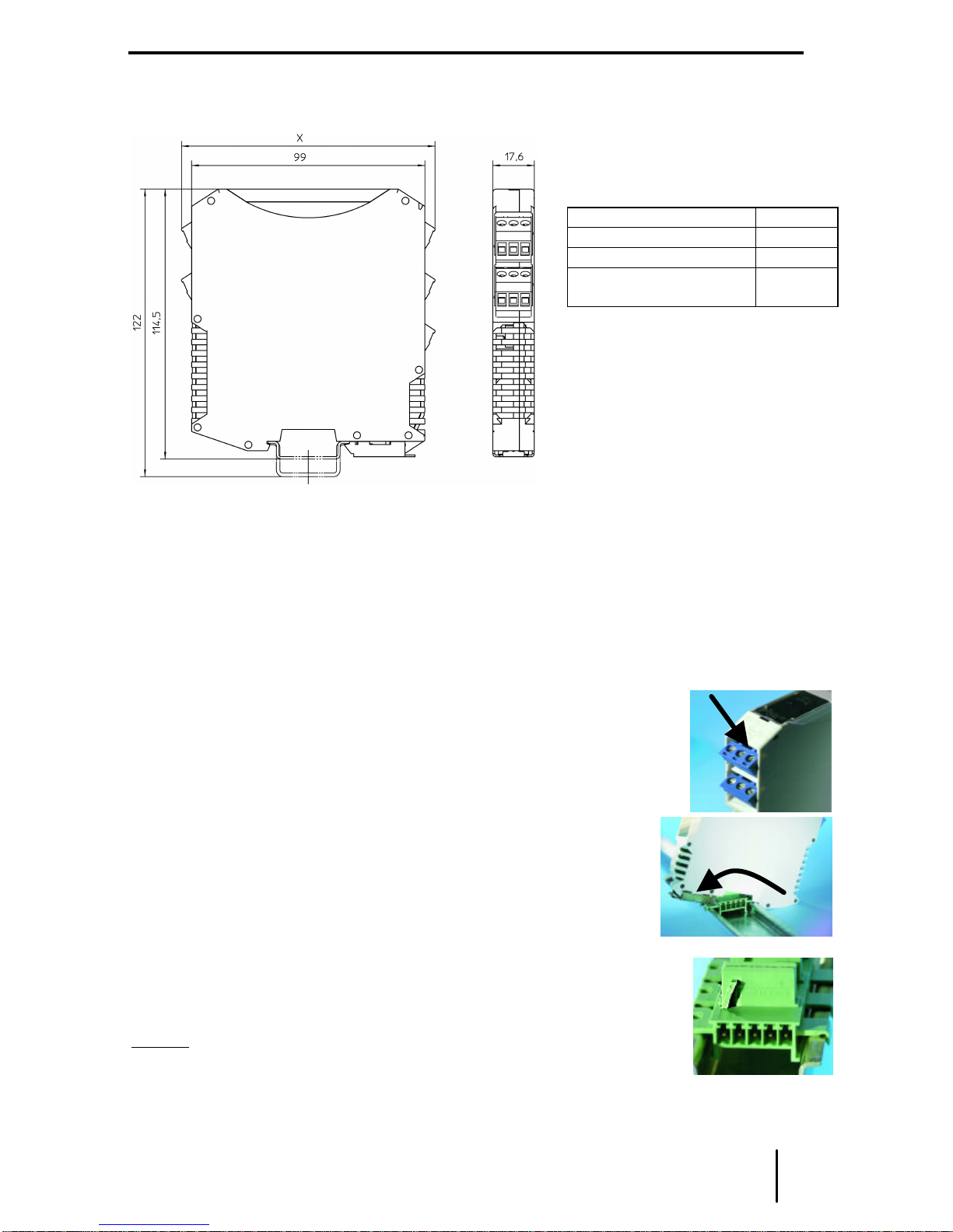
6.1 Maßzeichnung...........................................................................................................7
6.2 Installation..................................................................................................................7
6.3 Montage und Demontage..........................................................................................7
7Inbetriebnahme..............................................................................................................8
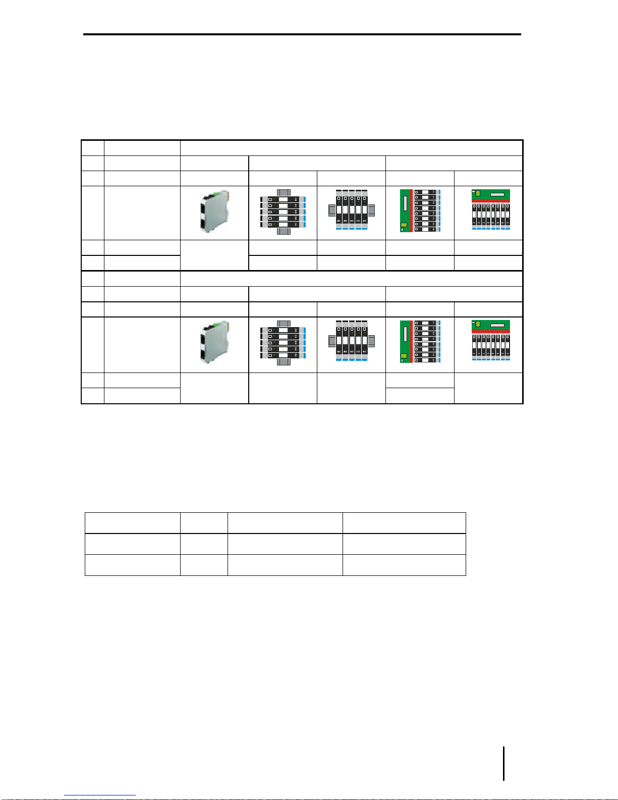
7.1 Anschlüsse.................................................................................................................8
7.2 Einstellungen .............................................................................................................8
8Betrieb-und Betriebszustände......................................................................................9
9Reparatur und Instandhaltung ......................................................................................9
10 Zubehör und Ersatzteile................................................................................................9
Contents
1Safety instructions.......................................................................................................10
2Conformity to standards..............................................................................................10
3Function.......................................................................................................................11
4Marking and technical data.........................................................................................11
5Engineering..................................................................................................................12
5.1 Max. ambient temperatures.....................................................................................12
5.2 Power dissipation.....................................................................................................12
5.3 Engineering of the power dissipation in cabinets ...................................................13
6Arrangement and fitting...............................................................................................14
6.1 Dimensions ..............................................................................................................14
6.2 Installation................................................................................................................14
6.3 Mounting and dismounting......................................................................................14
7Commissioning............................................................................................................15
7.1 Connections.............................................................................................................15
7.2 Settings ....................................................................................................................15
8Operation and operational states................................................................................16
9Maintenance and repair ..............................................................................................16
10 Accessories and spare parts.......................................................................................16
EG-Konformitätserklärung / EC-Declaration of Conformity ..................................................17
EG-Baumusterprüfbescheinigung..........................................................................................18
EC-Type Examination Certificate...........................................................................................19

deutsch Betriebsanleitung
Trennübertrager HART Eingang Typ 9163 3
1Sicherheitshinweise
In diesem Kapitel sind die wichtigsten Sicherheitsmaßnahmen zusammengefasst. Es
ergänzt die entsprechenden Vorschriften, zu deren Studium das verantwortliche Personal
verpflichtet ist.
Bei Arbeiten in explosionsgefährdeten Bereichen hängt die Sicherheit von Personen und
Anlagen von der Einhaltung aller relevanten Sicherheitsvorschriften ab. Das Montage-und
Wartungspersonal trägt deshalb eine besondere Verantwortung. Die Voraussetzung dafür
ist die genaue Kenntnis der geltenden Vorschriften und Bestimmungen.
Bei Errichtung und Betrieb ist Folgendes zu beachten:
•Es gelten die nationalen Montage-und Errichtungsvorschriften (z.B. EN 60079-14).
•Der Trennübertrager ist in Zone 2, Zone 22 oder außerhalb explosionsgefährdeter
Bereiche zu installieren.
•Bei Einsatz in Zone 2 ist der Trennübertrager in ein Gehäuse einzubauen, das den
Anforderungen der EN 50 021 genügt.
•Bei Einsatz in Zone 22 ist der Trennübertrager in ein Gehäuse einzubauen, das den
Anforderungen der EN 50 281 genügt.
•Bei Einsatz in Zone 2 oder Zone 22 dürfen an die eigensicheren Eingangsstromkreise
eigensichere Geräte der Zonen 1, 0, 21 und 20 angeschlossen werden.
•Der Trennübertrager darf nur an Geräte angeschlossen werden, in denen keine höheren
Spannungen als AC 250 V (50 Hz) auftreten können.
•Die sicherheitstechnischen Werte der / des angeschlossenen Feldgeräte/s müssen mit
den Angaben des Datenblattes bzw. der EG-Baumusterprüfbescheinigung
übereinstimmen.
•Bei Zusammenschaltungen mehrerer aktiver Betriebsmittel in einem eigensicheren
Stromkreis können sich andere sicherheitstechnische Werte ergeben. Hierbei kann die
Eigensicherheit gefährdet werden!
•Die nationalen Sicherheits-und Unfallverhütungsvorschriften
•Die allgemein anerkannten Regeln der Technik
•Die Sicherheitshinweise dieser Betriebsanleitung
•Beschädigungen können den Explosionsschutz aufheben..
Verwenden Sie das Gerät bestimmungsgemäß, nur für den zugelassenen Einsatzzweck
(siehe „Funktion“).
Fehlerhafter oder unzulässiger Einsatz sowie das Nichtbeachten der Hinweise dieser
Betriebsanleitung schließen eine Gewährleistung unsererseits aus.
Umbauten und Veränderungen am Gerät, die den Explosionsschutz beeinträchtigen, sind
nicht gestattet.
Das Gerät darf nur in unbeschädigtem, trockenem und sauberem Zustand eingebaut und
betrieben werden
2Normenkonformität
Die Trennübertrager Typen 9163 entsprechen den folgenden Normen bzw. der folgenden
Richtlinie:
•Richtlinie 94/9/EG
•EN 50 014, EN 50 020
•EN 50 021

Betriebsanleitung deutsch
4 Trennübertrager HART Eingang Typ 9163
3Funktion
Die Trennübertrager werden zum eigensicheren Betrieb von 3-oder 4-Leiter
Messumformern eingesetzt.
Die Geräte übertragen ein überlagertes HART-Kommunikationssignal bidirektional.
4Kennzeichnung und technische Daten
Hersteller
Typbezeichnung
CE-Kennzeichnung
Ex-Kennzeichnung
Kennzeichnung Explosionsschutz
und
Prüfstelle und Bescheinigungsnummer
Umgebungstemperaturbereich
R. STAHL
9163/*3-11-11
c0102
e
II (1) GD [EEx ia] IIC/IIB
II 3 G EEx nAC II T4
BVS 04 ATEX E 127 X
-20 °C … +60°C / 70 °C
Sicherheitstechnische Daten
Max. Ausgangsspannung Uo / Ausgangsstrom Io
max. Spannung, Ui
max. Strom, Ii
max. Leistung, Pi
innere Kapazität, Ci/ Induktivität, Li
Isolationsspannung Um
vernachlässigbar
30 V
150 mA
1 W
vernachlässigbar
253 V AC
Weitere Angaben und Wertekombinationen siehe EG-Baumusterprüfbescheinigung
Technische Daten (Auszug aus dem Datenblatt)
Hilfsenergie
Nennspannung UN24 V DC
Nennstrom (bei UNund IAmax) 1/2 Kanäle 60 / 80 mA
Leistungsaufnahme (bei UNund IAmax) 1/2 Kanäle 1,5 W / 1,9 W
Ex i Eingang
Signalbereich (ohne/mit HART)
Funktionsbereich
Eingangswiderstand (ohne/mit HART)
0…20 mA / 4…20 mA
0…24 mA
150 Ω/ 300 Ω
Ausgang
Bereich für Lastwiderstand (Bürde) 0…600 Ω
Umgebungsbedingungen
Betriebstemperatur -20...+60 °C / +70 °C
Lagertemperatur -40...+80 °C
relative Feuchte (keine Betauung) < 95 %
Weitere technische Daten sind dem aktuellen Datenblatt zu entnehmen.
Bei anderen vom Standard abweichenden Betriebsbedingungen nehmen Sie
bitte Rücksprache mit dem Hersteller.

deutsch Betriebsanleitung
Trennübertrager HART Eingang Typ 9163 5
5Projektierung
5.1 Maximal zulässige Umgebungstemperaturen
Die Geräte der Reihe IS pac sind über einen weiten Temperaturbereich einsetzbar. Je
nach Geräteausführung und Einbaubedingung ergeben sich unterschiedliche, maximal
zulässige Umgebungstemperaturen.
Belüftung:
Ohne Umluft
Installation:
Einzelgerät DIN-Schiene pac-Träger
Einbaulage:
beliebig vertikal horizontal vertikal horizontal
Kanäle
Typ:
19163/13-11-11 60 °C 70 °C 55 °C 65 °C
29163/23-11-11 70 °C 50 °C 60 °C 45 °C 60 °C
Belüftung:
Mit Umluft
Installation:
Einzelgerät DIN-Schiene pac-Träger
Einbaulage:
beliebig vertikal horizontal vertikal horizontal
Kanäle
Typ:
19163/13-11-11 70 °C
29163/23-11-11 70 °C 70 °C 70 °C 60 °C 70 °C
5.2 Verlustleistung
In den Datenblättern wird die max. Verlustleistung im Nennbetrieb (Ausgang 20 mA;
Hilfsenergie 24 V DC; Last = 250 Ω) angegeben. Da in der Praxis nicht alle Geräte
gleichzeitig unter Volllast betrieben werden, erfolgt die Projektierung üblicherweise mit
einer durchschnittlichen Verlustleistung von 70 %. (P70%).
Typ Kanäle max. Verlustleistung
70 % Verlustleistung
9163/13-11-11 11,4 W 1,0 W
9163/23-11-11 21,7 W 1,2 W

Betriebsanleitung deutsch
6 Trennübertrager HART Eingang Typ 9163
5.3 Projektierung der Verlustleistung in Schaltschränken
Beim Einbau von Geräten innerhalb von Schaltschränken wird der freie Luftstrom begrenzt
und die Temperatur steigt. Um die Temperaturerhöhung zu minimieren, ist es wichtig, die
Verlustleistung sowie die produzierte Wärme innerhalb des Schrankes zu optimieren.
a) Natürliche Konvektion in geschlossenen Schränken
•Anwendung: bei geringer Verlustleistung und wenn das System in einer staubigen oder
rauen Umgebung installiert ist
•Berechnung der maximal zulässigen Verlustleistung:
Pmax = ∆t * S * K
Pmax [W] max. zulässige Verlustleistung im Schaltschrank
∆t [°C] max. zulässige Temperaturerhöhung
S [m²] freie, wärme-emittierende Oberfläche des Schaltschrankes
K [(W/m²*°C)] thermischer Leitfähigkeitskoeffizient (lackierter Stahl: K = 5,5)
Der errechnete Wert Pmax muss kleiner als die Summe der durchschnittlichen Verlust-
leistungen (70 % der max. Verlustleistung) der eingebauten Geräte sein: Pmax < ∑P70%
b) Natürliche Konvektion in offenen Schränken
•Funktion: die Wärme wird mittels kühler Luftströme zwischen den Geräten verdrängt
•Voraussetzungen:
-Luftein und –auslassöffnungen an den unteren und oberen Enden des Schrankes
-der Weg des Luftstroms muss frei von Hindernissen gehalten werden
•Ergebnis: Je nach Ausführung kann die doppelte zulässige Verlustleistung wie unter a)
erreicht werden.
c) Erzwungene Belüftung mit Wärmetauscher in geschlossenen Schränken
•Anwendung: wenn entweder die Umgebung oder die hohe Verlustleistung keine
natürliche Konvektion erlauben
•Funktion: ein Wärmetauscher mit Lüfter saugt Luft in den Schrank und drückt sie in die
Wärmetauscherplatten, die durch einen zweiten Lüfter mit Umgebungsluft gekühlt
werden
•Ergebnis: Je nach Ausführung kann die 5-bis 6-fache zulässige Verlustleistung wie
unter a) erreicht werden.
d) Erzwungene Belüftung in offenen Schränken
•Funktion: Ein oder mehrere Lüfter erzeugen einen Luftstrom von der unteren
Schranköffnung an den Geräten vorbei durch die obere Schranköffnung hinaus.
•Berechnung des notwendigen Luftstroms:
Q = (3,1 * P70%) / ∆t
Q [m³/h] notwendiger Luftstrom
P70% [W] entstehende Verlustleistung (70 % der max. Verlustleistung)
∆t [°C] zulässige Temperaturerhöhung im Schaltschrank
e) Klimaanlage
•Anwendung: bei heißem Klima –eine Schranktemperatur gleich groß oder geringer als
die Umgebungstemperatur ist erreichbar.
•Funktion: Nutzung eines spezifisches Kältemaschinen-Systems oder des existierenden
Klimasystems für die Schrankkühlung.

deutsch Betriebsanleitung
Trennübertrager HART Eingang Typ 9163 7
6Anordnung und Montage
6.1 Maßzeichnung
6.2 Installation
Der Trennübertrager ist in der Zone 2, Zone 22 oder außerhalb explosionsgefährdeter
Bereiche zu installieren.
Bei Betrieb in Zone 2 bzw. Zone 22 ist der Trennübertrager in ein Gehäuse einzubauen,
das den Anforderungen der EN 50 021 bzw. EN 50 281 genügt (z.B. in ein Gehäuse Typ
8146 der Fa. R. STAHL Schaltgeräte GmbH).
6.3 Montage und Demontage
a) Die abziehbaren Klemmen
Alle Geräte sind mit abziehbaren Klemmen versehen. Zum Abziehen die
Klemmen mit z.B. einem Schraubendreher wie im Bild dargestellt lösen.
b) Montage auf DIN-Schienen nach EN 50 022
Geräte wie im Foto dargestellt ansetzen und auf die DIN-Schiene
aufschwenken. Dabei nicht verkanten. Zur Demontage den Fußriegel
mit einem Schraubendreher etwas herausziehen und das Modul
entnehmen.
c) Montage auf Hutschienen mit installiertem pac-Bus
Geräte wie im Foto oben dargestellt ansetzen und auf die DIN-Schiene
mit dem pac-Bus aufschwenken.
Dabei nicht verkanten.
Hinweis: um eine Verpolung bei der Installation zu Verhindern, sind die
pac-Bus-Elemente mit einer Codierleiste (siehe Foto) und die Module mit
dem entsprechendem Codierschlitz versehen.
Demontage wie unter b) beschrieben.
Maß X
Schraubklemmen 108 mm
Federzugklemmen 128 mm
Schneid-Klemm
Technik 131 mm

Betriebsanleitung deutsch
8 Trennübertrager HART Eingang Typ 9163
d) Montage im pac-Träger
Schwarze und grüne Klemmen entfernen.
Die IS pac Module wie unter a) und b) beschrieben ansetzen und
in den pac-Träger vollständig einschwenken.
Den roten Rasthebel mit leichtem Druck schließen. Der Rasthebel
muss vollständig eingerastet sein.
Zur Demontage den Rastmechanismus mit einem
Schraubendreher wie im Bild dargestellt öffnen. Das Modul wird
aus dem Steckplatz geschoben und kann entnommen werden.
7Inbetriebnahme
7.1 Anschlüsse
Hinweis: Für eine funktionierende HART-Kommunikation im Ausgangsstromkreis ist ein
Lastwiderstand (z.B. Eingangswiderstand der Eingangsbaugruppe) von mindestens 250 Ω
notwendig. Steht dieser nicht zur Verfügung, kann zusätzlich der interne 221 ΩWiderstand
verwendet werden. Der Anschluss muss dann an den Klemmen 3+/2-bzw. 4+/6-erfolgen.
Die maximale Ausgangslast verringert sich auf 479 Ω.
7.2 Einstellungen
Leitungsfehlererkennung LF
Deaktiviert *) Aktiviert
Kanal 1
Kanal 2
*) Standardeinstellung bei Auslieferung
Die Änderung der DIP-Schalter-Einstellungen ist im Betrieb auch in der Zone 2 und bei
angeschlossenen, eigensicheren Eingangssignalen zulässig.
LF1
LF2
ON
OFF
1
2
LF1
LF2
ON
OFF
1
2
1
3
4
6
+
-
24 V
pac-bus
5
2
7+
9-
8 LF
LF
24 V DC
+
-
10+
11-
Hazardousarea
1
2
1
2
Sicherer Bereich
Safearea
14+
15-
Ex-Bereich
HHT
+
-
R
L
221
Ω
221
Ω
HHT
+
-
R
L
HHT
HHT

deutsch Betriebsanleitung
Trennübertrager HART Eingang Typ 9163 9
8Betrieb-und Betriebszustände
Bevor Sie das Gerät in Betrieb nehmen, stellen Sie sicher, dass
•das Gerät vorschriftsmäßig installiert wurde
•das Gerät nicht beschädigt ist
•die Kabel ordnungsgemäß angeschlossen sind
9Reparatur und Instandhaltung
Es wird empfohlen, Reparaturen an unseren Geräten ausschließlich durch uns durchführen
zu lassen. In Ausnahmefällen kann die Reparatur auch durch eine andere, zugelassene
Stelle erfolgen.
Die Geräte sind wartungsfrei.
Fehlersuchplan:
Fehlererkennung Fehlerursache Fehlerbehebung
LED „PWR“ erloschen Hilfsenergie ausgefallen oder
Gerätesicherung defekt Hilfsenergieversorgung kontrollieren.
Bei defekter Sicherung das Gerät zur Reparatur
geben.
Führen die beschriebenen Vorgehensweisen nicht zum gewünschten Erfolg, wenden Sie
sich bitte an unsere nächste Vertriebsniederlassung. Zur schnellen Bearbeitung benötigt
diese von Ihnen folgende Angaben:
•Typ und Seriennummer,
•Kaufdaten,
•Fehlerbeschreibung,
•Einsatzzweck (insbesondere Eingangs-/Ausgangsbeschaltung)
10 Zubehör und Ersatzteile
Verwenden Sie nur Original-Zubehör sowie Original-Ersatzteile der R. STAHL
Schaltgeräte GmbH.

Operating Instructions english
10 Isolating Repeater HART Input Type 9163
1Safety instructions
The most important safety instructions are summarised in this chapter. It is intended to
supplement the relevant regulations which must be studied by the personnel responsible.
When working in hazardous areas, the safety of personnel and plant depends on
complying with all relevant safety regulations. Assembly and maintenance staff working on
installations therefore have a particular responsibility. The precondition for this is an
accurate knowledge of the applicable regulations and provisions.
When installing and operating the device, the following are to be observed:
•The national installation and assembly regulations (e.g. EN 60079-14) apply.
•The isolating repeater may be installed in Zone 2, Zone 22 or outside the explosion
hazard areas.
•If installed in Zone 2, the isolating repeater is to be fitted in an enclosure that meets the
requirements of EN 50 021.
•If installed in Zone 22, the isolating repeater is to be fitted in an enclosure that meets the
requirements of EN 50 281.
•When used in Zone 2 or Zone 22, intrinsically safe devices of Zones 1, 0, 21 and 20 may
be connected to the intrinsically safe input circuits.
•The isolating repeater may only be connected which will not be subjected to voltages
higher than AC 250 V (50 Hz).
•The safe maximum values of the connected field device(s) must correspond to the values
of the data sheet or the EC-type examination certificate.
•Interconnecting several active devices in an intrinsic safety circuit may result in other
safe maximum values. This could endanger the intrinsic safety!
•National safety and accident prevention regulations
•The generally recognised technical regulations
•The safety guidelines in these operating instructions
•Any damage can invalidate the explosion protection.
Use the device in accordance with the regulations and for its intended purpose only (see
“Function”).
Incorrect or impermissible use or non-compliance with these instructions invalidates our
warranty provision.
No changes to the devices or components impairing their explosion protection are
permitted.
The device may only be fitted and used if it is in an undamaged, dry and clean state.
2Conformity to standards
The Type 9163 isolating repeaters comply with the following standards and directives:
•Directive 94/9/EC
•EN 50 014, EN 50 020
•EN 50 021

english Operating Instructions
Isolating Repeater HART Input Type 9163 11
3Function
The isolating repeaters are used for intrinsically safe operation of 3-and 4-wire
transmitters.
The devices bidirectionally transfer a superimposed HART communications signal.
4Marking and technical data
Manufacturer
Type designation
CE marking
Ex-marking
Explosion protection marking
and
Testing authority and certificate number
Ambient temperature range
R. STAHL
9163/*6-11-11
c0102
e
II (1) GD [EEx ia] IIC/IIB
II 3 G EEx nAC II T4
BVS 04 ATEX E 127 X
-20 °C … +60°C / 70 °C
Safety data
Max. output voltage Uo/ output current Io
Max. voltage Ui
Max. current Ii
Max. power Pi
internal capacitance, Ci/ inductance, Li
Insulation voltage Um
negligible
30 V
150 mA
1 W
negligible
253 V AC
See EC-type examination certificate for further information and value combinations
Technical data (extract from the data sheet)
Power supply
Nominal voltage UN24 VDC
Nominal current (at UNand IAmax)100 mA
Power consumption (at UNand IAmax)2.4 W
I.S. Input
Signal range (without/with HART)
Functional range
Input resistance (without/with HART)
0…20 mA / 4…20 mA
0…24 mA
150 Ω/ 300 Ω
Output
Range for load resistance 0…600 Ω
Ambient conditions
Operating temperature -20...+60 °C / +70 °C
Storage temperature -40...+80 °C
Relative humidity (no condensation) < 95 %
Additional technical data can be found in the current data sheet.
Please consult with the manufacturer before operating under conditions which
deviate from the standard operating conditions.

Operating Instructions english
12 Isolating Repeater HART Input Type 9163
5Engineering
5.1 Max. ambient temperatures
The IS pac isolators can be used over a wide temperature range. Depending on the
isolator version and installation method different maximum ambient temperatures may
result.
Ventilation:
without ventilation
Installation:
Single unit DIN-rail pac-Carrier
Orientation:
any vertical horizontal vertical horizontal
Channels
Type:
19163/13-11-11 60 °C 70 °C 55 °C 65 °C
29163/23-11-11 70 °C 50 °C 60 °C 45 °C 60 °C
Ventilation:
with ventilation
Installation:
Single unit DIN-Schiene pac-Carrier
Orientation:
any vertical horizontal vertical horizontal
Channels
Type:
19163/13-11-11 70 °C
29163/23-11-11 70 °C 70 °C 70 °C 60 °C 70 °C
5.2 Power dissipation
Data sheets are describing the maximum power dissipation in standard operation (output
20 mA; power supply 24 V DC; load = 250 Ω). In practice not all isolators are working with
full load. Therefore engineering is done typically with an average power dissipation of 70 %
(P70%).
Type Channels max. power dissipation 70 % power dissipation
9163/13-11-11 11,4 W 1,0 W
9163/23-11-11 21,7 W 1,2 W

english Operating Instructions
Isolating Repeater HART Input Type 9163 13
5.3 Engineering of the power dissipation in cabinets
When electronic devices are integrated in cabinets free air movement is restricted and the
temperature rises. To minimise the temperature rise it is important to optimise the power
dissipation as well as the elimination of the produced heat inside a cabinet.
a) Natural Convection in closed cabinets
•Application: when the dissipated power is moderate and when the system operates in a
dusty or harsh environment
•Calculation of the maximum allowed power dissipation:
Pmax = ∆t * S * K
Pmax [W] max. allowed power dissipation in the cabinet
∆t [°C] max. allowed temperature rise
S [m²] free, heat emitting surface of the cabinet
K [(W/m²*°C)] thermal emitting coefficient (K=5.5 for painted steel sheets)
The calculated value for Pmax has to be smaller than the total average power dissipation
(70 % of max. power dissipation) of the installed isolators: Pmax < ∑P70%
b) Natural convection in open cabinets
•Function: the heat is removed by cool air flowing through the devices
•Requirements:
-inlet and outlet ports in the lower and upper ends of the cabinet
-the air flow path must be kept free from obstacles.
•Result: Depending on the engineering the improvement can reach a two times higher
power dissipation as with a)
c) Forced ventilation with heat exchanger in closed cabinets
•Application: when either the harsh environment or the high dissipated power do not
allow natural convection
•Function: a heat exchanger with a fan pulls the air into the cabinet and pushes it into the
heat exchanger plates that are cooled by the external ambient air moved by a second
fan.
•Result: Depending on the engineering the improvement can reach a 5 or 6 times
higher power dissipation as with a)
d) Forced ventilation in open cabinets
•Function: the filtered air is taken from the bottom cabinet openings by one or more fans,
flows through the devices, and finally exits at the top of the cabinet.
•Calculation of the required air flow:
Q = (3.1 * P70%) / ∆t
Q [m³/h] required air flow
P70% [W] dissipated power (70 % of max. power dissipation)
∆t [°C] allowed temperature rise in the cabinet
e) Air conditioned cabinets
•Application: for hot climates -it is possible to reach a cabinet temperature equal or even
lower than the ambient temperature
•Function: a specific refrigerating system or the existing air conditioning system can be
used for cabinet conditioning

Operating Instructions english
14 Isolating Repeater HART Input Type 9163
6Arrangement and fitting
6.1 Dimensions
6.2 Installation
The isolating repeater may be installed in Zone 2 or outside hazardous areas.
In the case of operation in Zone 2 the isolating repeater must be fitted in an enclosure
which complies with the requirements of EN 50 021 (e.g. in an enclosure type 8146 from
the R. STAHL Schaltgeräte GmbH company).
6.3 Mounting and dismounting
a) Detachable terminals
All devices are provided with detachable terminals. A screwdriver is
needed to remove the terminals (as shown in the picture).
b) Mounting on DIN rails in accordance with EN 50 022
Set the device on the DIN rail and tilt/snap onto the rail as depicted.
Do not set at an angle. For removal, pull the base latch out a little
with a screwdriver and remove the module.
c) Mounting on DIN rails with an already-installed pac-Bus
As depicted in the photo, set the device in position on the pac-Bus (already mounted on the
DIN rail) and tilt/snap until it locks in.
Do not tilt at an angle to either side when snapping onto the pac-Bus.
Note:In order to prevent pole reversal during installation, the pac-Bus
elements have been equipped with a keyed connection plug (see photo).
The module is fitted with a matching slot.
Dismount as described below in b).
Size X
Screw terminals 108 mm
Spring clamp terminals 128 mm
Insulation cutting 131 mm

english Operating Instructions
Isolating Repeater HART Input Type 9163 15
d) Mounting in the pac-Carrier
Remove the black and green terminals.
Set the IS pac modules in place as described in a) and b) and
completely tilt/snap into the pac-Carrier.
Close the red latching lever using gentle pressure. The latching
lever must engage completely.
To dismount, use a screwdriver to open the latching mechanism as
shown in the picture. The module is nudged out of the slot and can
be removed.
7Commissioning
7.1 Connections
Note: A working HART communication requires a minimum load resistance (e.g. input
resistance of input card) of 250 Ωin the output circuit. Is this not available the internal 221
Ωresistance can be used. Then the connection has to be done on terminals 3+/2-or 4+/6-.
The maximum output load is reduced to 479 Ω.
7.2 Settings
Line Fault detection LF
Deactivated *) Activated
Channel 1
Channel 2
*) Default factory setting
The DIP switch settings may be changed during operation in Zone 2 as well and in the
case of connected, intrinsically safe input signals.
LF1
LF2
ON
OFF
1
2
LF1
LI1
LF2
LI2
ON
OFF
1
2
1
3
4
6
+
-
24 V
pac-bus
5
2
7+
9-
8 LF
LF
24 V DC
+
-
10+
11-
Hazardousarea
1
2
1
2
Sicherer Bereich
Safearea
14+
15-
Ex-Bereich
HHT
+
-
R
L
221
Ω
221
Ω
HHT
+
-
R
L
HHT
HHT

Operating Instructions english
16 Isolating Repeater HART Input Type 9163
8Operation and operational states
Before commissioning the device, please ensure that:
•the device has been installed in accordance with the standards
•the device is not damaged
•the cables are properly connected
9Maintenance and repair
It is recommended that all repairs to our devices be carried out by R. Stahl. In exceptional
cases, repair may be performed by approved third-parties.
The devices are maintenance-free.
Troubleshooting chart:
Error detection Cause of error Corrective action
“PWR” LED not lit Power supply failure or device fuse is
defective Check power supply.
If device fuse is defective, send device in for
repair.
If the procedure described above does not obtain the desired result, please contact your
local R.STAHL sales and service representative. In order to quickly process your request,
please provide us with the following information:
•Type and serial number,
•Purchase date(s),
•Description of the error,
•Application description (particularly the configuration of the
input/output circuitry)
10 Accessories and spare parts
Use only original accessories and spare parts from R. STAHL Schaltgeräte GmbH.

17
EG-Konformitätserklärung / EC-Declaration of Conformity

18
EG-Baumusterprüfbescheinigung

19
EC-Type Examination Certificate

R. STAHL Schaltgeräte GmbH
Am Bahnhof 30
74638 Waldenburg (Württ.) –Germany
www.stahl.de ID-Nr. 91 636 01 31 0 S-BA-9163-001-de/en-09/2004
Table of contents
Languages:
Other Stahl Repeater manuals

Stahl
Stahl 9163 Series User manual

Stahl
Stahl Ispac 9170 1 Series User manual

Stahl
Stahl 9163 Series User manual

Stahl
Stahl ispac 9186/12 User manual

Stahl
Stahl ispac 9170/0 Series User manual

Stahl
Stahl 9170/11-11-61 User manual

Stahl
Stahl 9170/12-12-13 User manual

Stahl
Stahl 9186 5-12-11 Series User manual

Stahl
Stahl 9185 Series User manual

Stahl
Stahl ISpac 9170/21-30-10 User manual