Stahl 8491/1 User manual

BETRIEBSANLEITUNG
OPERATING INSTRUCTIONS
INSTRUCTIONS DE SERVICE
Signalhupe
Signal horn
Trompe Sonore
Typ/Type 8491/1

INHALT
1 Symbole ............................................................................................................................1
2 Sicherheitshinweise ...........................................................................................................1
3 Normenkonformität ............................................................................................................1
4 Funktion..............................................................................................................................2
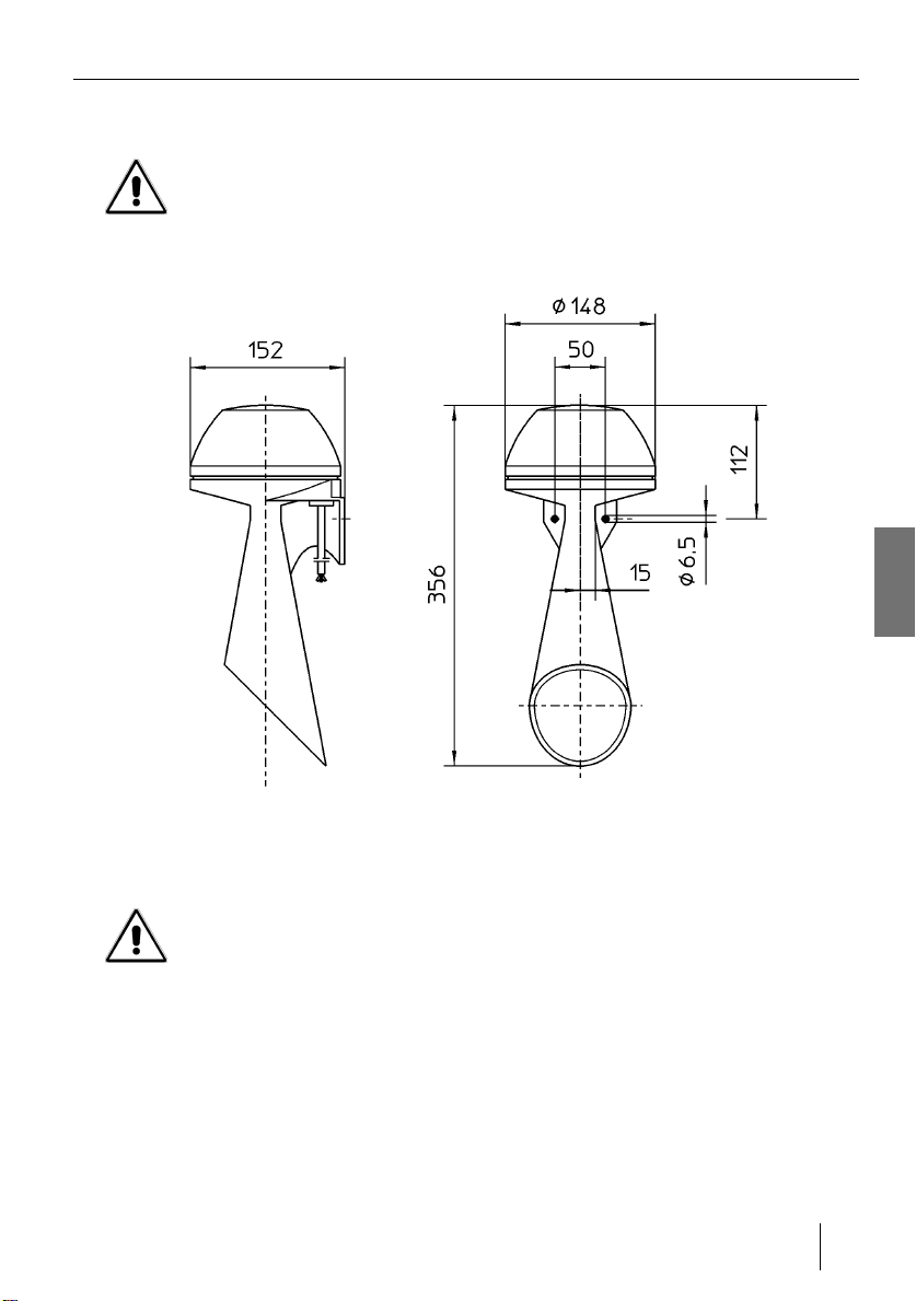
5 Technische Daten .............................................................................................................2
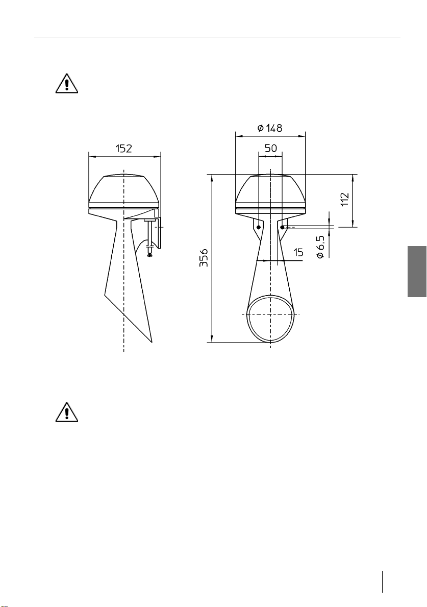
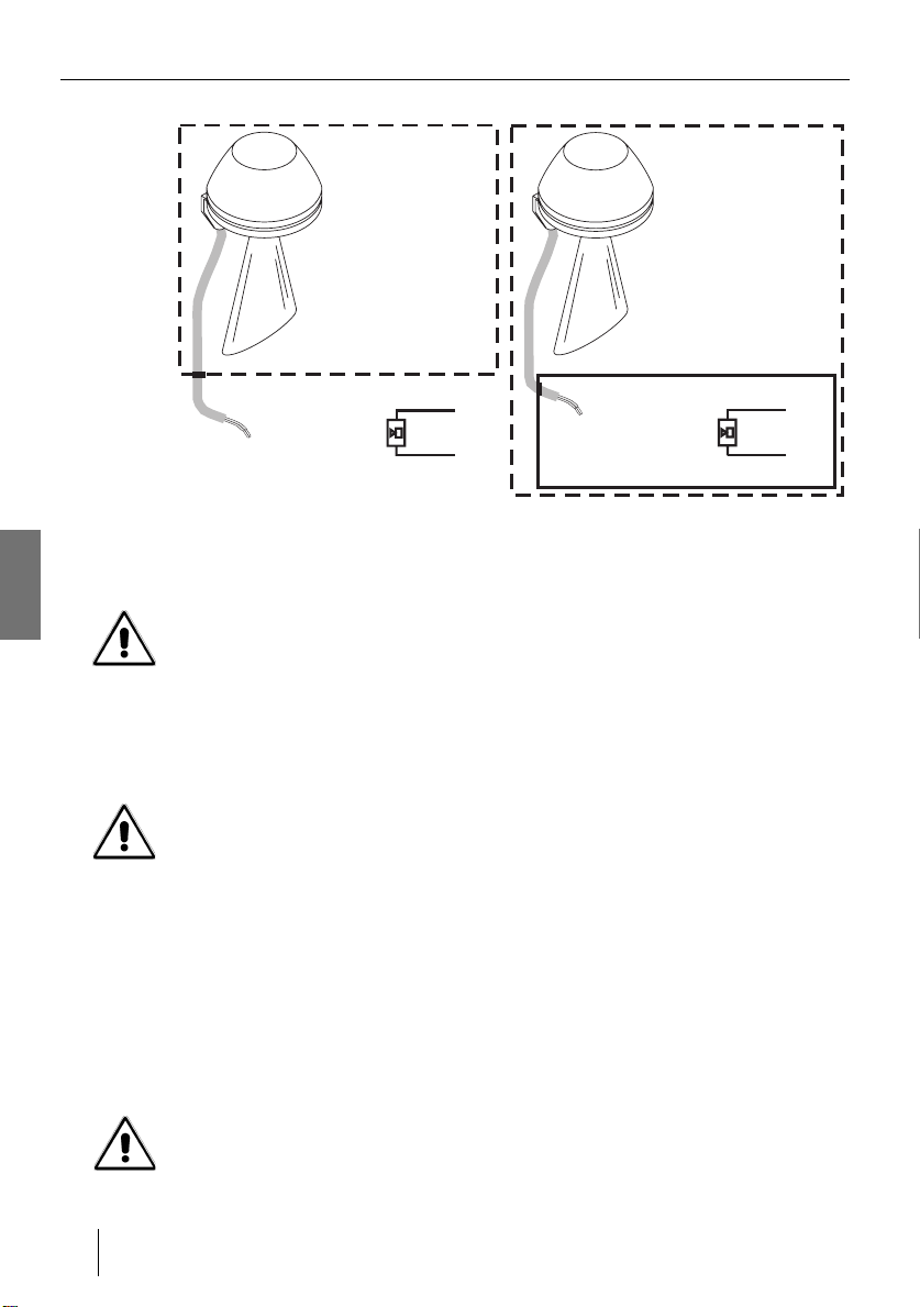
6 Anordnung und Montage ...................................................................................................3
7 Installation ..........................................................................................................................3
8 Inbetriebnahme .................................................................................................................4
9 Instandhaltung ...................................................................................................................4
10 Transport und Lagerung ....................................................................................................4
11 Entsorgung.........................................................................................................................4
CONTENTS
1 Symbols .............................................................................................................................5
2 Safety instructions .............................................................................................................5
3 Conformity to standards ....................................................................................................5
4 Function..............................................................................................................................6
5 Technical data ...................................................................................................................6
6 Arrangement and Fitting ....................................................................................................7
7 Installation ..........................................................................................................................7
8 Commissioning ..................................................................................................................8
9 Servicing ............................................................................................................................8
10 Transportation and storage ...............................................................................................8
11 Disposal..............................................................................................................................8
SOMMAIRE
1 Symboles ...........................................................................................................................9
2 Consignes de sécurité .......................................................................................................9
3 Conformité aux normes .....................................................................................................9
4 Fonction............................................................................................................................10
5 Caractéristiques techniques .............................................................................................10
6 Disposition et montage ....................................................................................................11
7 Installation ........................................................................................................................11
8 Mise en service ...............................................................................................................12
9 Maintenance.....................................................................................................................12
10 Transport et stockage ......................................................................................................12
11 Réglementation concernant les déchets ..........................................................................12
Anhang / Appendix / Annexes .................................................................................... A1
Technische Änderungen vorbehalten.
We reserve the right to make technical changes without notice.
Sous resérve de modification techniques.

Symbole
1
Signalhorn Typ 8491/1
deutsch
1 Symbole
Achtung!
Diese Grafik kennzeichnet Hinweise, bei deren Nichtbeachtung Ihre Gesundheit oder
die Funktionsfähigkeit des Gerätes bzw. der Komponente gefährdet ist.
Hinweis
Diese Grafik kennzeichnet wichtige Zusatzinformationen, Tipps und Empfehlungen.
2 Sicherheitshinweise
In diesem Kapitel sind die wichtigsten Sicherheitsmaßnahmen zusammengefasst. Es
ergänzt die entsprechenden Vorschriften, zu deren Studium das verantwortliche Perso-
nal verpflichtet ist.
Bei Arbeiten in explosionsgefährdeten Bereichen hängt die Sicherheit von Personen
und Anlagen von der Einhaltung aller relevanten Sicherheitsvorschriften ab. Das Mon-
tage- und Wartungspersonal trägt deshalb eine besondere Verantwortung. Vorausset-
zung ist die genaue Kenntnis der geltenden Vorschriften und Bestimmungen.
Beachten Sie als Anwender:
•die nationalen Sicherheits- und Unfallverhütungsvorschriften,
•die nationalen Montage- und Errichtungsvorschriften (z.B. IEC 60079-14),
•die allgemein anerkannten Regeln der Technik,
•die Sicherheitshinweise und Angaben dieser Betriebsanleitung,
•die Kennwerte und Bemessungsbetriebsbedingungen der Typ- und Datenschilder,
• der Schalldruck des Akustikelements kann bei geringem Abstand das Gehör
schädigen,
• wenn durch einen Ausfall des Signalgeräts eine Gefährdung von Menschen oder
Beschädigung von Betriebseinrichtungen möglich ist, muss dies durch zusätzliche
Sicherheitsmaßnahmen verhindert werden,
• die Signalhupe schaltet bei Überhitzung durch zu langen Betrieb ab und schaltet erst
nach Abkühlung automatisch wieder ein.
Verwenden Sie das Gerät bestimmungsgemäß, nur für den zugelassenen Einsatz-
zweck (siehe “Funktion” auf Seite 2). Fehlerhafter und unzulässiger Einsatz sowie das
Nichtbeachten der Hinweise dieser Betriebsanleitung schließen eine Gewährleistung
unsererseits aus. Veränderungen an dem Gerät, die den Explosionsschutz betreffen,
sind nicht gestattet. Das Gerät darf nur in unbeschädigtem, trockenem und sauberem
Zustand eingebaut werden.
3 Normenkonformität
Die Geräte entsprechen den folgenden Normen bzw. der folgenden Richtlinie:
• EN 50014, EN 50028
• Richtlinie 94/9/EG
Das Gerät ist für den Einsatz in explosionsgefährdeten Bereichen der Zonen 1 und 2
zugelassen.

Funktion
2Signalhorn Typ 8491/1
deutsch
4 Funktion
Das Gerät wurde zum Warnen, Rufen und Melden in explosionsgefährdeten Bereichen
der Gruppe II Kategorie 2G entwickelt. Die Zündschutzart EEx m II T5 erlaubt den Ein-
satz dieses Signalgeräts in fast allen Ex-Bereichen der Zone 1 und 2. Der Explosions-
schutz wird durch Vergusskapselung „m“ erreicht.
5 Technische Daten
Bei abweichenden Betriebsbedingungen nehmen Sie bitte Rücksprache mit dem Her-
steller.
5.1 Explosionsschutz
• Explosionsschutz
Gerätegruppe und Kategorie II 2G
• Prüfbescheinigung BVS 03 ATEX E 159 X
• Zündschutzart gemäß EN 50014 EEx m II
• Einsetzbar in Temperaturklasse T5
5.2 Schutzart
• Schutzgrad nach IEC 60529 IP 55
5.3 Umgebungsbedingungen
• Umgebungstemperaturbereich -40 °C ... +50 °C
5.4 Mechanische Daten
• Maße 152 mm x 148 mm x 356 mm
• Material PC/ABS-Blend, silikonfrei
• Gewicht 1300 g
• Schalldruck max. 105 dB
5.5 Elektrische Daten
• Bemessungsspannung, -strom, vorzuschaltende Sicherung:
• Anschluss Kabel 3 m, 2 x 0,75 mm2
• Einschaltdauer ED 70%
Bemessungs-
spannung Spannungs- Frequenz Bemessungs- Sicherung,
bereich strom flink
24 V, DC 21,6...26,4 V 350 mA F 0,5 A
24 V, AC 21,6...26,4 V 50 Hz 450 mA F 0,63 A
42...48 V, AC 37,8...52,8 V 50 Hz 220 mA F 0,315 A
115 V, AC
120 V AC 102,5...126,5 V
108...131 V 50/60 Hz
60 Hz 205 mA
200 mA F 0,315 A
230 V, AC 208...250 V 50 Hz 70 mA F 0,125 A
Tabelle 5-1: Bemessungsspannung, -strom und vorzuschaltende Sicherung

Anordnung und Montage
3
Signalhorn Typ 8491/1
deutsch
6 Anordnung und Montage
Montieren Sie das Gerät immer mit dem Schallaustritt nach unten
6.1 Maßzeichnungen
Abbildung 6-1: Maßzeichnungen (alle Maße in mm)
7 Installation
Die Geräte dürfen nur von einer Elektrofachkraft installiert werden.
Beachten Sie Bemessungsspannung und -strom (siehe Typenschild).
Schalten Sie vor Anschluss und bei Beschädigung des Gerätes die Versorgungs- bzw.
Netzspannung ab und sichern Sie das Gerät gegen unbeabsichtigtes Wiedereinschal-
ten.
• Verlegen Sie die Anschlussleitung fest.
• Schalten Sie die Sicherung vor (siehe Tabelle 5-1 auf Seite 2).
• Schließen Sie das Kabelende außerhalb des Ex-Bereiches oder in einem Klemmka-
sten EEx „e“ an (siehe Abbildung “Kabelenden-Anschluss” auf Seite 4).

Inbetriebnahme
4Signalhorn Typ 8491/1
deutsch
Abbildung 7-1: Kabelenden-Anschluss
8 Inbetriebnahme
Das Gerät darf nur in komplett montiertem Zustand betrieben werden.
Stellen Sie vor der Inbetriebnahme sicher, dass
• das Gerät vorschriftsmäßig installiert wurde,
• der Anschluss ordnungsgemäß ausgeführt,
• das Gerät nicht beschädigt ist.
9 Instandhaltung und Wartung
Beachten Sie die geltenden nationalen Bestimmungen im Einsatzland!
Das Gerät darf nur mit einem feuchten Tuch gereinigt werden.
Überprüfen Sie im Rahmen der Wartung:
• die Leitungen auf festen Sitz,
• die Einhaltung der zulässigen Temperatur (gemäß EN 50014),
• die bestimmungsgemäße Funktion.
10 Transport und Lagerung
Transportieren und lagern Sie das Gerät nur in der Originalverpackung.
11 Entsorgung
Beachten Sie bei der Entsorgung des Gerätes die nationalen Abfallbeseitigungsvor-
schriften.
L (+)
BR
BL N (-)
Ex-Bereich
L (+)
BR
BL N (-)
Ex-Bereich
“e” Anschlußkasten

Symbols
5
Signal horn Type 8491/1
english
1 Symbols
Warning!
This symbol indicates advice which, if ignored, puts your health or the ability of the de-
vice or devices to function at risk.
Note
Marks important additional information, tips and recommendations.
2 Safety instructions
The most important safety instructions are summarized in this section. They supplement
the relevant regulations which must be studied by the personnel responsible.
When working in hazardous areas, the safety of personnel and plant depends on com-
plying with all relevant safety regulations. Assembly and maintenance staff working on
installations therefore have a particular responsibility. They require precise knowledge
of the applicable standards and regulations.
As user, please observe:
•National safety and accident prevention regulations.
•National installation regulations (e.g. IEC 60079-14).
•Generally recognised technical regulations.
•Safety guidelines and information in these operating instructions.
•Characteristic values and rated operating conditions on the rating and data plates.
• The sound pressure of the signal element can cause damage to hearing when used
at close quarters.
• In case of equipment failure, additional safety precautions should be taken to avoid
possible danger to persons.
• Should the horn overheat due to excessively long operation it will shut down and
automatically restart once it has been cooled down.
Use the appliance in accordance with the regulations and for its intended purpose
only (see “Function” on page 6). Incorrect or impermissible use or non-compliance with
these instructions invalidates our warranty provision. No changes to the appliance im-
pairing its explosion protection is permitted. Further, it may only be fitted if undamaged,
dry and clean.
3 Conformity to standards
The appliance complies with the following standards and directive:
• EN 50014, EN 50028
• Directive 94/9/EG
The appliance is approved for use in hazardous areas zones
1 and 2.

Function
6Signal horn Type 8491/1
english
4 Function
The appliance was developed as a signalling appliance for warning and calling being
used in hazardous group II category 2G locations. The protection class EEx m II T5 al-
lows this signalling appliance to be used in almost all hazardous zone 1 and 2 locations.
Explosion protection is achieved bay means of a casting compound ’m’.
5 Technical data
Please consult the manufacturer if operating conditions are non-standard.
5.1 Explosion protection
• Explosion protection
Group an category II 2G
• Test certificate BVS 03 ATEX E 159 X
• Type of protection to EN 50014 EEx m II
• May be used in temperature class T5
5.2 Type of protection
• Degree of protection IP 55 (in accordance with IEC 60529)
5.3 Ambient conditions
• Ambient temperature range -40 °C ... +50 °C
5.4 Mechanical data
• Dimension 152 mm x 148 mm x 356 mm
• Material PC/ABS-Blend, silicone free
• Weight 1300 g
• Sound pressure max. 105 dB
5.5 Electrical data
• Rated voltage, current, series-connected fuse:
Tabelle 5-1: Rated voltage, current, series-connected fuse
• Power supply cable 3 m, 2 x 0,75 mm2
• Operating factor (duty cycle) 70%
Rated
voltage Voltage Frequency Rated Fuse blow
range current rating
24 V, DC 21,6...26,4 V 350 mA F 0,5 A
24 V, AC 21,6...26,4 V 50 Hz 450 mA F 0,63 A
42...48 V, AC 37,8...52,8 V 50 Hz 220 mA F 0,315 A
115 V, AC
120 V AC 102,5...126,5 V
108...131 V 50/60 Hz
60 Hz 205 mA
200 mA F 0,315 A
230 V, AC 208...250 V 50 Hz 70 mA F 0,125 A

Arrangement and fitting
7
Signal horn Type 8491/1
english
6 Arrangement and fitting
Always mount the device so that the sound output is oriented-downward.
6.1 Dimension drawings
Figure 6-1: Dimensions (all dimensions in mm)
7 Installation
Only trained electrical-personnel are authorized to install the devices.
Adhere to the rated voltage and current specifications. (see identification plate).
Before installing and in case of damage to the device, disconnect the device from the
power supply/mains power and secure against unintentional reconnection of the power.
• Arrange and secure the connection wiring in the wiring space.
• Connect the fuse (see Table 5-1 on page 6).
• Connect the cable end outside the hazardous area or within an EEx „e“ terminal box
(see Figure “Connect the cable end” on page 8).

Commissioning
8Signal horn Type 8491/1
english
Figure 7-1: Connect the cable end
8 Commissioning
Only operate the appliance when completely assembled!
Before commissioning, ensure that:
• the appliance has been installed in accordance with the standards,
• the connections have been correctly made,
• the appliance is not damaged.
9 Servicing
Observe the relevant national regulations in the country of use!
The device should only be cleaned using a moist clean rag.
The following must be checked during maintenance:
• that the cable is securely seated,
• compliance with permitted temperatures to 50014,
• function in accordance with regulations.
10 Transport, storage
Transport and store the appliance in its original packing only.
11 Disposal
When disposing of the appliance, observe the national standards for refuse disposal.
L (+)
BR
BL N (-)
hazardous zone
L (+)
BR
BL N (-)
hazardous zone
’e’ connection box

Symboles
9
Trompe Sonore Type 8491/1
français
1 Symboles
Attention!
Ce symbole caractérise les remarques, dont la non-observation met en danger votre
santé ou le fonctionnement de l'appareil ou des composants.
Remarque
Ce symbole caractérise des informations complémentaires, conseils et recommandati-
ons d'importance.
2 Consignes de sécurité
Dans ce chapitre sont résumées les mesures de sécurité les plus importantes. Il ne peut
en aucun cas se substituer aux prescriptions correspondantes, dont l'étude demeure
obligatoire pour le personnel responsable.
Lors du travail dans les zones à risque d'explosion, la sécurité des personnes et des in-
stallations dépend du respect de toutes les consignes de sécurité correspondantes. Le
personnel chargé du montage et de la maintenance possède à cet égard une grande
responsabilité et doit connaître parfaitement les prescriptions et dispositions légales en
vigueur.
Veuillez observer en tant qu’utilisateur:
•les prescriptions nationales et de prévention des accidents,
•les instructions nationales de montage (par ex. CEI 60079-14),
•les règles de l'art dans le domaine technique,
•les consignes de sécurité et données du présent mode d'emploi,
•les caractéristiques techniques et les conditions d’utilisation indiquées sur les pla-
ques signalétiques,
• la puissance sonore de l’élément acoustique peut nuire à l’ouie en cas de trop
grande proximité,
• si une panne ou un défaut de l’avertisseur présentait un danger pour le personnel ou
les installations, prévenir ceci par des mesures de sécurité supplémentaires,
• en cas d’une surchauffe dû à un fonctionnement permanent, l’avertisseur s’éteindra
pour automatiquement refonctionner.
L’appareil ne doit être utilisé que pour l'application pour laquelle il a été prévu (voir
“Fonction” sur page 10). Une utilisation défectueuse ou anormale ainsi que le non-re-
spect des consignes du présent mode d'emploi excluent toute clause de garantie. Des
modifications sur les appareils, susceptibles d’entraver la protection antidéflagrante, ne
sont pas autorisées. Les appareils ne doivent être montés et exploités que dans un état
intact, sec et propre.
3 Conformité aux normes
Les appareils sont conformes aux normes et directives suivantes:
• EN 50014, EN 50028
• Directive 94/9/EG
L’utilisation des appareils est autorisée en atmosphère explosible zones 1 et 2.

Fonction
10 Trompe Sonore Type 8491/1
français
4 Fonction
L’appareil a été développé pour l’avertissement, l’appel et la signalisation dans les en-
vironnements exposifs du groupe II categorie 2G. La protection EEx m II T5 permet ici
une utilisations de cet appareil de signalisation dans pratiquement tous les environne-
ments explosifs des zones 1 et 2. La protection antidéflagrante est assurée par l’encap-
sulage <<m>>.
5 Caractéristiques techniques
En cas de conditions d’utilisation différentes, veuillez contacter le constructeur.
5.1 Protection antidéflagrante
• Protection antidéflagrante
Groupe d’appareils et catégorie II 2G
• Certificat de conformité BVS 03 ATEX E 159 X
• Mode de protection selon EN 50014 EEx m II
• Utilisable en classe de température T5
5.2 Mode de protection
• Degré de protection selon IEC 60529 IP 55
5.3 Conditions ambiantes
• Température ambiante -40 °C ... +50 °C
5.4 Données mécaniques
• Dimension 152 mm x 148 mm x 356 mm
• Matériau PC/ABS-mélange; sans silicone
• Poids 1300 g
• Puissance sonore max. 105 dB
5.5 Données électriques
• Tension assignée, courant assigné, fusible à placer en amont:
Tableu 5-1: Tension assignée, courant assigné, fusible à placer en amont
• Connexion câble de raccordement 3 m, 2 x 0,75 mm2
• Durée de mise en circuit 70%
Tension
assignée Tolerance Fréquenz Currant Coupe-circuit à
de son assignée action instantanée
24 V, DC 21,6...26,4 V 350 mA F 0,5 A
24 V, AC 21,6...26,4 V 50 Hz 450 mA F 0,63 A
42...48 V, AC 37,8...52,8 V 50 Hz 220 mA F 0,315 A
115 V, AC
120 V AC 102,5...126,5 V
108...131 V 50/60 Hz
60 Hz 205 mA
200 mA F 0,315 A
230 V, AC 208...250 V 50 Hz 70 mA F 0,125 A

Disposition et montage
11
Trompe Sonore Type 8491/1
français
6 Disposition et montage
Montez toujours l’appa-reil de façon à ce que l’orifice de sortie acoustique soit dirigé
vers le bas.
6.1 Plans d’encombrement
Figure 6-1: Plans d’encombrement (toutes les dimensions sont indiquées en mm)
7 Installation
Seuls des électriciens à formation adéquate ont le droit d’installer les appareils.
Tenez compte de la tension assignée et du courant assigné (voir plaque d’identité).
Coupez toujours la tension d’alimentation et la tension de réseau avant de raccorder
l’appareil ou si l’appareil est endommagé et protégez-le contre une remise en circuit non
intentionnée.
• Posez le câble de raccordement.
• Placez le fusible en amont (voir tableu 5-1 sur page 10).
• Raccordez l’extrémité du câble en dehors de l’atmosphère explosive ou dans une
boîte de bornes EEx ‘e’(voir figure “Raccordement de l’extrémité du câble” sur
page 12)

Mise en service
12 Trompe Sonore Type 8491/1
français
Figure 7-1: Raccordement de l’extrémité du câble
8 Mise en service
N’employer l’appareil que lorsqu’ il est complètement monté
Avant la mise en service, assurez-vous que:
• l’appareil a été installé correctement,
• le raccordement a été effectué correctement,
• l’appareil n’est pas endommagé,
9 Maintenance et entretien
Observez les réglementations en vigueur dans le pays d'utilisation!
L’appareil doit être nettoyé en utilisant seulement un chiffon humide.
Contrôlez lors de l'entretien:
• le serrage des vis de connexion,
• le maintien des températures autorisées selon EN 50014,
• le bon usage des composants.
10 Transport et stockage
Le transport et le stockage sont autorisés uniquement en emballage d'origine.
11 Réglementation concernant les déchets
Respectez les réglementations nationales en matière d'élimination des déchets.
L (+)
BR
BL N (-)
zone explosifs
L (+)
BR
BL N (-)
zone explosifs
«e» boîte à prise de courant

Anhang / Appendix / Annexes
Typ/Type 8491 A-1
1.

Anhang / Appendix / Annexes
Typ/Type 8491
A-2


Eine Kopie der EG-Baumusterprüfbescheinigung finden Sie unter
www.stahl.de/de/ex/certificates.php
A copy of the EC type examination is available under
www.stahl.de/en/ex/certificates.php
Une copie du certificat de conformité (CE) est disponible sous
www.stahl.de/en/ex/certificates.php
Wenn Sie die Betriebsanleitung in einer anderen Sprache der Europäischen Union benötigen,
sprechen Sie bitte Ihre R. STAHL Vertretung vor Ort an.
Should you require the operating instructions in one of the other European Community languages,
please feel free to contact your R. STAHL representative.
Si vous avez besoin des instructions de mise en service dans une autre langue de l'Union Euro-
péenne, prière de contacter votre Représentant R. STAHL.
En caso necesario podrá solicitar de su representante R. STAHL estas instrucciones de servicio
en otro idioma de la Union Europea.
Se desiderate la traduzione del manuale operativo in un´altra lingua della Comunit à Europea po-
tete richiederla al vostro rappresentante R. STAHL.
Indien noodzakelijk kan de vertaling van deze gebruiksinstructie in een andere EU-taal worden
opgevraagd bij uw R. STAHL-vertegenwoordiging.
Har ni behov av montage och skötselinstruktionen till annat EU-språk kontakta din R.STAHL re-
presentant.
Se for necessária a tradução destas instruções de operação para outro idioma da União Euro-
peia, pode solicita-la junto do seu representante R. STAHL.
Montagevejledningen kan oversættes til andre EU-sprog og rekvireres hos Deres R. STAHL le-
verandør.
Tarvittaessa tämän käyttöohjeen käännös on saatavissa toisella EU:n kielellä Teidän R. STAHL-
edustajaltanne.
Εαν χρειασθει, µεταφραση της χρησεως σε αλλη γλωσσα της ΕΕ, µπορει vαζητηθει απο
τωv Αvτιπροσωπο της R. STAHL.

84 916 01 30 0 S-BA-8491-04-de/en/fr-04.2005
310.750.004
R. STAHL Schaltgeräte GmbH
Am Bahnhof 30
74638 Waldenburg (Württ.)
www.stahl.de
06_8491-1_Hupe RS.fm Seite 2 Freitag, 4. März 2005 7:51 07
Table of contents
Languages:
Other Stahl Safety Equipment manuals

Stahl
Stahl ispac 9176 User manual

Stahl
Stahl HUPE Technical manual

Stahl
Stahl Reihe 8146/5-V37 User manual

Stahl
Stahl 9180 User manual

Stahl
Stahl MEXE User manual

Stahl
Stahl 8146/5-V37 Series User manual

Stahl
Stahl Ex e User manual

Stahl
Stahl YA6S Series User manual

Stahl
Stahl pac-Carrier 9195 Series User manual