Contents
2
DE
EN
FR
IT
ES
RU
NL
DK
SE
FI
PT
GR
PL
CZ
SK
HU
SL
RO
BG
LT
EE
CH
KR
CN
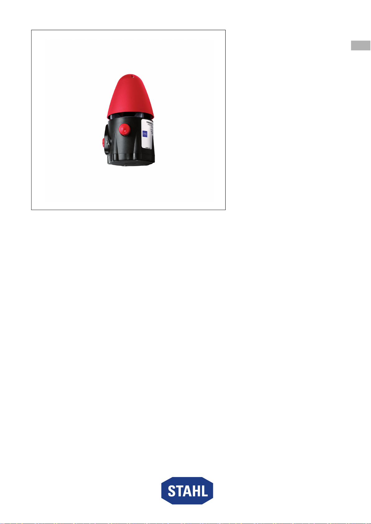
GRP audible signal – 110 db(A),
flameproof
Series YA6S
Contents
1 General information .............................................................................................3
1.1 Manufacturer........................................................................................................3
1.2 Information regarding the operating instructions..................................................3
1.3 Further documents...............................................................................................3
1.4 Conformity with standards and regulations..........................................................3
2 Explanation of symbols........................................................................................3
2.1 Symbols used in these operating instructions......................................................3
2.2 Warning notes......................................................................................................4
2.3 Symbols on the device.........................................................................................5
3 Safety notes.........................................................................................................6
3.1 Operating instructions storage.............................................................................6
3.2 Personnel qualification.........................................................................................6
3.3 Safe use...............................................................................................................6
3.4 Modifications and alterations ...............................................................................7
4 Function and device design .................................................................................7
4.1 Function ...............................................................................................................7
5 Technical data......................................................................................................8
6 Transport and storage..........................................................................................9
7 Mounting and installation ...................................................................................10
7.1 Dimensions/fastening dimensions .....................................................................10
7.2 Mounting/dismounting, operating position .........................................................11
7.3 Installation..........................................................................................................12
8 Commissioning ..................................................................................................20
9 Operation ...........................................................................................................21
9.1 Troubleshooting .................................................................................................21
10 Maintenance, overhaul, repair ...........................................................................21
10.1 Maintenance and overhaul.................................................................................21
10.2 Repairs...............................................................................................................21
10.3 Returning the device..........................................................................................22
11 Cleaning.............................................................................................................22
12 Disposal .............................................................................................................22
13 Accessories and spare parts..............................................................................22