Stanley Fatmax TLM165S User manual

E
NL
GR
PT
FIN
HU
BG
LV
ES
DK
CZ
E
NO
SK
RO
F
SE
RU
PT
PL
SI
EE
TLM165s
User Manual
Please read these instructions before operating the product.
www.StanleyTools.com
DOC100270398

C
D
AAA
AAA
AAA
1
2
B
AAA
AAA
2
Figures
A
DW0165
4.5V DC
2
1
3
4
31
2
7
5
6
89

3
E
2
1
3
4
H
I
=
=
=
=
F
G
≤ 45°
≤ 45°

4
EContents
•User Safety
•Battery Safety
•Loading Batteries
•Using the Tool
•Warranty
•Error Codes
•
Retain all sections of this manual for future reference.
User Safety
WARNING:
Carefully read the Safety Instructions and
Product Manual before using this product. The
person responsible forthe product must ensure
that all users understand and adhere to these
instructions.
WARNING:
The following label information is placed on your
lasertool to inform you of the laserclass foryour
convenience and safety.
DW0165
4.5V DC
DW0165S
FCC ID: xxxxxDW0165S
IC: xxxxx-DW0165S
4.5V DC
TheTLM165s tool emits a visible laser beam, as
shown in Figure A1 . The laser beam emitted is Laser
Class 2 per IEC 60825-1 and complies with 21 CFR
1040.10 and 1040.11 except for deviations pursuant to
Laser Notice No. 50, dated June 24, 2007.
WARNING:
While the laser tool is in operation, be careful not
to expose youreyes to the emitting laserbeam
(red light source). Exposure to a laserbeam
foran extended time period may be hazardous
to youreyes. Do not look into thebeam with
optical aids.
WARNING:
To reduce the risk of injury, usermust read the
Product Usermanual, Laser Safety manual, and
Battery Safety information.
FCC ID: 2ANWF-TLM165
IC: 23237-TLM165

5
E
Battery Safety
WARNING: Batteries can explode or leak and
cause serious injury or re. To reduce the risk:
ALWAYS follow all instructions and warnings on
the battery label and package.
DO NOT short any battery terminals.
DO NOT charge alkaline batteries.
DO NOT mix old and new batteries. Replace all
of them at the same time with new batteries of
the same brand and type.
DO NOT mix battery chemistries.
DO NOT dispose of batteries in re.
ALWAYS keep batteries out of reach of children.
ALWAYS remove batteries if the device will not
be used for several months.
NOTE: Ensure that the recommended batteries
are used.
NOTE: Ensure the batteries are inserted in the
correct manner, with the correct polarity.
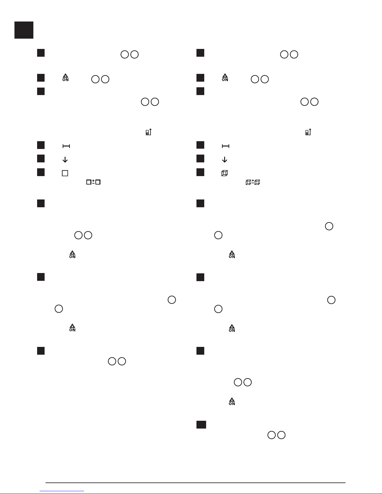
Loading Batteries
1. Pull up the tool stand on the back of the tool (Figure
D1).
2. Pull up the battery compartment latch on the back of
the tool (Figure D2and D3).
3. Insert three AAA batteries, making sure to position
the -and +ends of each battery as noted inside the
battery compartment (Figure D4).
4. Push the battery door down until it snaps in place
(Figure D5).
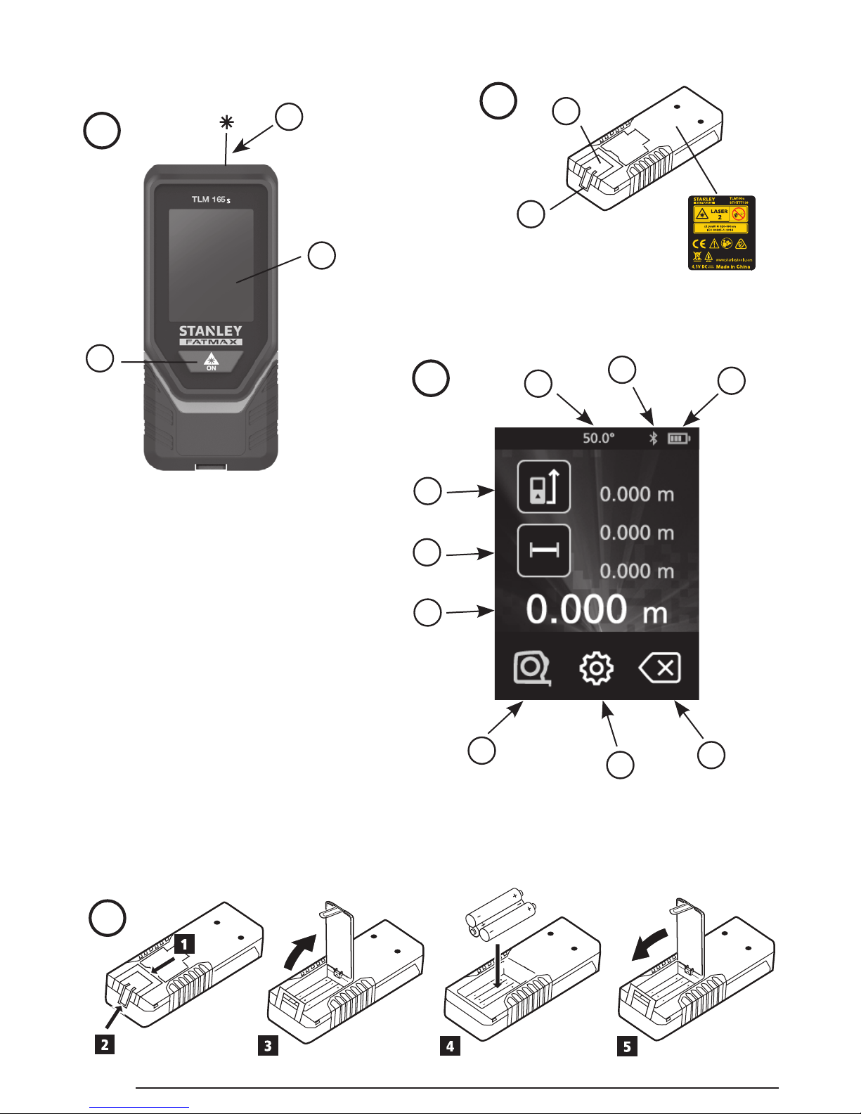
When the tool is ON, the battery level appears in the
display window (Figure C1).
Using the Tool
Measuring Distance to a Wall or Object
1. Point the tool's laser (Figure A1) toward a wall or
object, and not toward anyone's eyes.
2. Click (Figure A3) to turn the tool on.
3. By default, distances are measured from the bottom
of the tool to a wall or object (Figure E3).
To measure distances from the top or middle of the
tool, or from the tool's endpiece (when it is flipped
open to measure from a corner), click .
4. Make sure is displayed to indicate that you want
to measure a distance.
5. Point the tool's laser (Figure A1) toward the wall
or object whose distance you need to measure.
6. Click to measure the distance from the tool to the
wall or object.
7. At the bottom of the display window, view the current
measurement (Figure C6).
To take a new measurement, click to move the current
measurement up to the previous line on the display
window. Then repeat steps 5-7.
Measuring Distances Continuously
To take a series of measurements as you move around,
change to Continuous Measure mode.
1. Point the tool's laser (Figure A1) toward a wall or
object, and not toward anyone's eyes.
2. Click (Figure A3) to turn the tool on.
3. By default, distances are measured from the bottom
of the tool to a wall or object (Figure E3).
To measure distances from the top or middle of the
tool, or from the tool's endpiece (when it is flipped
open to measure from a corner), click .
4. Click to turn on the Continuous Measure mode
(Figure C5).
5. Point the tool's laser (Figure A1) toward the wall
or object whose distance you need to measure.
6. At the bottom of the display window, view the current
measurement (Figure C6), which will keep
changing as you move the tool.
7. To take the current measurement (from the tool to the
wall or object) and exit Continuous Measure mode,
click .
To take a new measurement, click to move the current
measurement up to the previous line on the display
window. Then repeat steps 4-7.

6
EMeasuring Area
You can measure the area of a wall, floor, or object.
1. Point the tool's laser (Figure A1) toward a wall or
object, and not toward anyone's eyes.
2. Click (Figure A3) to turn the tool on.
3. By default, distances are measured from the bottom
of the tool to a wall or object (Figure E3).
To measure distances from the top or middle of the
tool, or from the tool's endpiece (when it is flipped
open to measure from a corner), click .
4. Click .
5. Click .
6. Click to determine the area of one wall, floor, or
object, or click to add or subtract the areas of
two walls, floors, or objects.
7. Measure the width.
• Position the tool at one end of the target (wall, floor,
or object) and point the laser dot across the width.
(Figure F1shows where to position the tool if
you are measuring from the bottom of the tool.)
• Click to display the width measurement at the
top of the display window.
8. Measure the length.
• Position the tool at one end of the target and
point the laser dot across the length. (Figure F
2shows where to position the tool if you are
measuring from the bottom of the tool.)
• Click to display the length measurement on the
second line of the display window.
9. View the Area measurement at the bottom of the
display window (Figure C6).
Measuring Volume
You can measure the volume of a room or object.
1. Point the tool's laser (Figure A1) toward a wall or
object, and not toward anyone's eyes.
2. Click (Figure A3) to turn the tool on.
3. By default, distances are measured from the bottom
of the tool to a wall or object (Figure E3).
To measure distances from the top or middle of the
tool, or from the tool's endpiece (when it is flipped
open to measure from a corner), click .
4. Click .
5. Click .
6. Click to determine the volume of one room or
object, or click to add or subtract the volumes
of two rooms or objects.
7. Measure the width.
• Position the tool at one end of the target and
point the laser dot across the width. (Figure G
1shows where to position the tool if you are
measuring from the bottom of the tool.)
• Click to display the width measurement at the
top of the display window.
8. Measure the length.
• Position the tool at one end of the target and
point the laser dot across the length. (Figure G
2shows where to position the tool if you are
measuring from the bottom of the tool.)
• Click to display the length measurement on the
second line of the display window.
9. Measure the height.
• Positon the tool at one end of the target and point
the laser dot across the height.
(Figure G3shows where to position the tool if
you are measuring from the bottom of the tool).
• Click to display the height measurement on the
third line of the display window.
10. View the Volume measurement at the bottom of the
display window (Figure C6).

7
E
Measuring the Height of a Tall Object
If you need to measure the height of a tall object (e.g.,
a tall building), you can calculate the height based on
the distances from the same point to 2 or 3 points on
the object. The tool will use the Pythagorean Theorem
(C2=A2+B2) to calculate the height.
• If the tool can be positioned opposite the bottom
of the tall object (to create an angle ≤45°), use
the distances to 2 points to calculate the height
(Figure G).
• If the tool must be pointed downward to aim at
the bottom of the tall object (to create an angle >
45°), use the distances to 3 points to calculate the
height (Figure H).
Using the Distances to 2 Points
1. Click (Figure A3)to turn on the tool.
2. Click 3 times to show on the display
window (Figure C5).
3. Aim the laser at the top of the tool (Figure A1)
at the highest point of the building or object whose
height you need to measure (Figure G#1).
4. Click to measure the distance to the top of the
tall object.
5. From the same point, aim the laser at the lowest
point of the building or object (Figure G#2).
6. Click to measure the distance.
7. On the bottom line of the display window, view the
height of the building or object.
Using the Distances to 3 Points
1. Click (Figure A3)to turn on the tool.
2. Click 4 times to show on the display window
(Figure C5).
3. Point the laser (Figure A1) at the highest point
of the building or object whose height you need to
measure (Figure H#1).
4. Click to measure the distance to the top of the
tall object.
5. From the same point, aim the laser on a horizontal
line straight ahead toward the building or object
(Figure H#2).
6. Click to measure the distance.
7. From the same point, aim the laser at the lowest
point of the building or object (Figure H#3).
8. Click to measure the distance.
9. On the bottom line of the display window, view the
height of the building or object.
Adding Measurements
You can add two measurements to get a total
measurement of the two distances.
1. Point the tool's laser (Figure A1) toward a wall or
object, and not toward anyone's eyes.
2. Click (Figure A3) to turn the tool on.
3. By default, distances are measured from the bottom
of the tool to a wall or object (Figure E3).
To measure distances from the top or middle of the
tool, or from the tool's endpiece (when it is flipped
open to measure from a corner), click .
4. Click .
5. Click .
6. Select +to indicate that you want to add
measurements.
7. Point the tool's laser toward the wall or object whose
distance you need to measure.
8. Click to measure the distance from the tool to the
wall or object.
9. Point the tool's laser toward the next wall or object.
10. Click to measure the distance and add it to the
previous measurement.
11. View the total of the two measurements at the bottom
of the display window (Figure C6).
Subtracting Measurements
You can subtract one measurement from another.
1. Point the tool's laser (Figure A1) toward a wall or
object, and not toward anyone's eyes.
2. Click (Figure A3) to turn the tool on.

8
E3. By default, distances are measured from the bottom
of the tool to a wall or object (Figure E3).
To measure distances from the top or middle of the
tool, or from the tool's endpiece (when it is flipped
open to measure from a corner), click .
4. Click .
5. Click .
6. Select -to indicate that you want to subtract one
measurement from another.
7. Point the tool's laser toward the wall or object whose
distance you need to measure.
8. Click to measure the distance from the tool to the
wall or object.
9. Point the tool's laser toward the next wall or object.
10. Click to measure the distance and subtract it from
the previous measurement.
11. View the difference between the two measurements
at the bottom of the display window (Figure C6).
Changing the Unit of Measure
Once the current measurement is taken (the device is
not in Continuous Measure mode), you can set the unit
of measure to fractional ft (6'02"9/16), inches (74 9/16 in),
decimal ft (6.21 ft), decimal inches (3.21 in), or meters
(1.894 m).
1. On the touchscreen, click .
2. Click ft/m.
3. Click the desired unit of measure.
• 0'00" 0/00
• 0" 0/00
• 0'00" ft
• 0.00 in
• 0.000 m
4. Click to return to the previous screen.
Using Your TLM165s With
You can use the Bluetooth®capability of your TLM165s
to pair it with the STANLEY®Smart Connect application
on your cell phone or tablet, and then record accurate
measurements in your floor plans.
1. From either or , download the
STANLEY®Smart Connect application to your cell
phone or tablet.
2. Using the STANLEY®Smart Connect application,
capture the room or space for which you want to
record the measurements, and build your floor plan.
3. On the TLM165s keypad, click to turn on the tool.
4. If the Bluetooth®icon does not appear on the display
window (Figure C2), click and then to turn
on Bluetooth®.
5. Use the STANLEY®Smart Connect application to
pair your cell phone or tablet to the TLM165s.
6. Use the TLM165s to measure each wall in the room
or space captured in the floor plan, and sync the
measurements to the floor plan.
7. Using the STANLEY®Smart Connect application,
save the floor plan.
Once you have saved the floor plan, you can export it
to one of several different file formats, including PDF,
DXF, or JPG, and print it or email it to other people (your
realtor, home center, etc.).
“THE BLUETOOTH®WORD MARK AND LOGOS ARE REGIS-
TERED TRADEMARKS OWNED BY BLUETOOTH SIG, INC. AND
ANY USE OF SUCH MARKS BY STANLEY TOOLS IS UNDER
LICENSE. OTHER TRADEMARKS AND TRADE NAMES ARE
THOSE OF THEIR RESPECTIVE OWNERS.”
Turning Off the Sound
Each time you take a measurement, the tool will beep.
You can turn off the beeps.
1. On the touchscreen, click .
2. Click to display .
3. Click to return to the previous screen.

9
E
Turning Off the Tool
The tool can be turned off in either of these ways:
• Press and hold for 10 seconds. When you release after 10 seconds, the tool will turn off.
• If you do not use the tool for 90 seconds, it will automatically turn off.
Warranty
STANLEY warrants this product for a period of (2) years against deficiencies in material and workmanship. This LIMITED
WARRANTY does not cover products that are improperly used, abused, altered, or repaired. Please call 866-786-5924 for more
information or return instructions. Unless otherwise noted, STANLEY will repair without cost, any STANLEY product found to be
defective, including parts and labor charges, or at STANLEY’s option, will replace such tools or refund the purchase price, less
the amount for depreciation, in exchange for the defective tool. THIS LIMITED WARRANTY EXCLUDES ALL INCIDENTAL OR
CONSEQUENTIAL DAMAGES. Some states do not allow the exclusion or limitation of incidental or consequential damages,
so these limitations may not apply to you. This TWO YEAR LIMITED WARRANTY gives you specific legal rights that may vary
from state to state. In addition to the warranty, STANLEY Lasers are covered by: 30-Day Money Back Guarantee. If you are not
completely satisfied with the performance of your STANLEY Laser for any reason, you can return it within 30 days from the date of
purchase with a receipt for a full refund.
IMPORTANT NOTE: The customer is responsible for the correct use and care of the instrument. Moreover, the customer is
completely responsible for periodically checking the accuracy of the laser unit, and therefore for the calibration of the instrument.
Calibration and care are not covered by warranty.
Error Codes
If INFO appears on the display window with a Code number, perform the corresponding Corrective Action.
Code Description Corrective Action
101 Received Signal Too Weak,
Measuring Time Too Long
Use the target plate or change the target surface.
102 Received Signal Too High Target is too reective. Use the target plate or change the
target surface.
201 Too Much Background Light Reduce the background light on the target area.
202 Laser Beam Interrupted Remove the obstacle and repeat the measurement.
203 Insufcient Power Replace the batteries.
301 Temperature Too High Allow the device to cool down to a temperature within the
specied Operating Temperature Range.
302 Temperature Too Low Allow the device to warm up to a temperature within the
specied Operating Temperature Range.
401 Hardware Error Switch the device on/off several times. If the error still occurs,
return the defective device to the Service Center or distributor.
Refer to the Warranty.
402 Unknown Error Contact the Service Center or distributor. Refer to the Warranty.

10
ESpecications
Range 6in to 165ft (.15m to 50m)
Measuring Accuracy* ± 1/16in (± 1.5mm)*
Resolution** 1/16in (1mm)**
Laser Class Class 2 (IEC/EN60825-1: 2007/2014)
Laser Type ≤ 1.0mW @ 620-690nm
Laser/Backlight Automatic Switch-off After 30s
Unit Automatic Switch-off After 90s
Continuous Measuring Yes
Area Yes
Volume Yes
Pythagoras 2-Point Yes
Pythagoras 3-Point Yes
Endpiece to measure from corners or
grooves
Yes. Flip open the endpiece at the bottom of the tool when
you need to t the tool into corners or grooves that are not
at 180° angles. If a corner is at 90°, the endpiece can be
used to hold the tool up against something.
Battery Life (3 x AAA) Up to 3000 Measurements (2500 with )
Dimension (H x D x W) 4.72 x 1.91 x 1.02in (120 x 48.5 x 26mm)
Weight (with Batteries) 9.88oz (280g)
Storage Temperature Range 13° F ~ 158° F (-25° C ~ +70 C)
Operating Temperature Range 32° F ~ 104° F (0° C ~ +40° C)
*Measuring Accuracy depends on the current conditions:
• Under favorable conditions (good target surface and room temperature), up to 33ft (10m).
• Under unfavorable conditions (bright sunlight, a very weak reecting target surface, or large temperature uctuations), the
error can increase to ± 0.002 in/ft (± 0.2mm/m) for distances over 33ft (10m).
**Resolution is the nest measurement you can see. In inches, that is 1/16". In mm, that is 1mm.

—Reorient or relocate the receiving antenna.
—Increase the separation between the equipment and
receiver.
—Connect the equipment into an outlet on a circuit
different from that to which the receiver is connected.
—Consult the dealer or an experienced radio/TV
technician for help.
Caution—use of controls or adjustments or performance
of procedures other than those specified herein may
result in hazardous radiation exposure.
Caution:
This device complies with Part 15 of the FCC Rules /
Industry Canada licence-exempt RSS standard(s).
Operation is subject to the following two conditions: (1)
this device may not cause harmful interference, and (2)
this device must accept any interference received,
including interference that may cause undesired
operation.
Le présent appareil est conforme aux CNR d'Industrie
Canada applicables aux appareils radio exempts de
licence. L'exploitation est autorisée aux deux conditions
suivantes : (1) l'appareil ne doit pas produire de
brouillage, et (2) l'utilisateur de l'appareil doit accepter
tout brouillage radioélectrique subi, même si le
brouillage est susceptible d'en compromettre le
fonctionnement.
Changes or modifications not expressly approved by the
party responsible for compliance could void the user's
authority to operate the equipment.
This equipment has been tested and found to comply
with the limits for a Class B digital device, pursuant to
part 15 of the FCC Rules. These limits are designed to
provide reasonable protection against harmful
interference in a residential installation. This equipment
generates uses and can radiate radio frequency energy
and, if not installed and used in accordance with the
instructions, may cause harmful interference to radio
communications. However, there is no guarantee that
interference will not occur in a particular installation. If
this equipment does cause harmful interference to radio
or television reception, which can be determined by
turning the equipment off and on, the user is
encouraged to try to correct the interference to radio
communications. However, there is no guarantee that
interference will not occur in a particular installation. If
this equipment does cause harmful interference to radio
or television reception, which can be determined by
turning the equipment off and on, the user is
encouraged to try to correct the interference by one or
more of the following measures:
11

Notes:

© 2017 Stanley Tools
701 E. Joppa Road
Towson, Maryland 21286
U.S. & Canada Only
Made in China
021472
December 2017
Other manuals for Fatmax TLM165S
2
Table of contents
Other Stanley Analytical Instrument manuals