D2620-01-04 CN5841 SEM320X User guide Page 3of 4
6~2 ELECTRICAL (Continued).
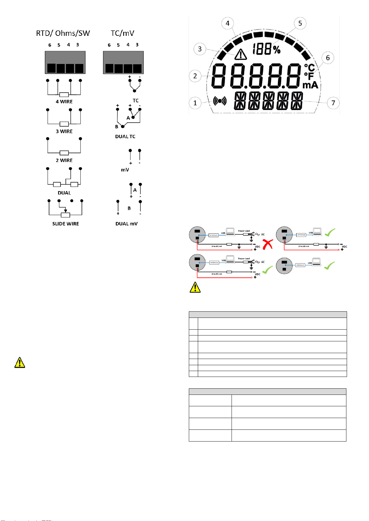
Input sensor connections.
Figure 2: Input connections.
RTD input wires must be equal length and type.
Sensor connections are as figure 2: to maintain BS EN61326
compliance, sensor wires must be less than 3 metres. All sensor
connections must be isolated from ground.
For RTD dual input use two wire RTDs. If required, user-offsets can be done on both
inputs to known input values.
Thermocouple inputs must use correct compensation cable.
Sensor connections are as figure 2: to maintain BS EN61326 compliance, sensor wires
must be less than 3 metres. All sensor connections must be isolated from ground.
For dual thermocouple input, both thermocouples must be of the same type.
If required, user-offsets can be done on both inputs to known input values.
(4 to 20) mA Loop connections.
Ensure all other aspects of the installation comply with the requirements of this document.
To maintain CE compliance, the (4 to 20) mA current loop must be tied to a local earth at
one point; this is normally at the power supply.
Use twisted pair or screened cables for cable lengths greater than 3 metres. Maximum
cable length 1000 metres.
.
7~USER CONFIGURATION.
IMPORTANT.
READ COMPLETE SECTION BEFORE ATTEMPTING CONFIGURATION.
WARNING.
For configuring or reading live data if using a grounded input or output, it is important
not to connect the programming USB lead to a mains powered computer. It is possible
to damage the instrument if connected in this way.
To avoid damage, use one of the following methods:
•Disconnect the input and output connectors before configuration, reconnect the
connectors after configuration.
•Use a laptop-type computer running from its battery power supply, not connected
to a mains supply. This is recommended for reading live device data or offsetting a
device if already installed in the field.
•Use an approved USB isolator (USBX Config) between the computer and the
device, see supplier for details.
DISPLAY: The display provides five 7-segment characters for display of value and 5
14-segment characters for messages, together with a 10-segment bar graph, % of
output signal display and five icons. The display can operate in an ambient temperature
range of (-20 to 85) °C, but at temperatures lower than -5 °C (due to the slower LCD
speed) scrolled messaging is not practical. The display’s high contrast offers clear
readouts at low as well as high ambient light and direct sunlight.
Figure 3: Display layout.
1. Indicated HART communications
2. Main numeric value display
3. Signal out-of-range warning icon
4. Bar graph of output
5. % of output
6. Bespoke °C and °F temperature indication devices (mA not used)
display.
7. % Message/additional units display
7~1 USBSpeedLink USER CONFIGURATION.
A USB configuration module is required for connecting the device to the PC. Refer to
your supplier for details.
The device can be configured whilst connected and powered but a portable battery
powered computer must be used to avoid the effects of ground loops if the (4 to20) mA
loop is grounded. This may cause damage to the display device.
Figure 4: Configuration connection.
Configuration must take place in the non- hazadous area with the approved
USBX Config module.
Configuration steps.