manuals.online logo
Brands
  1. Home
  2. •
  3. Brands
  4. •
  5. Staubli
  6. •
  7. Cables And Connectors
  8. •
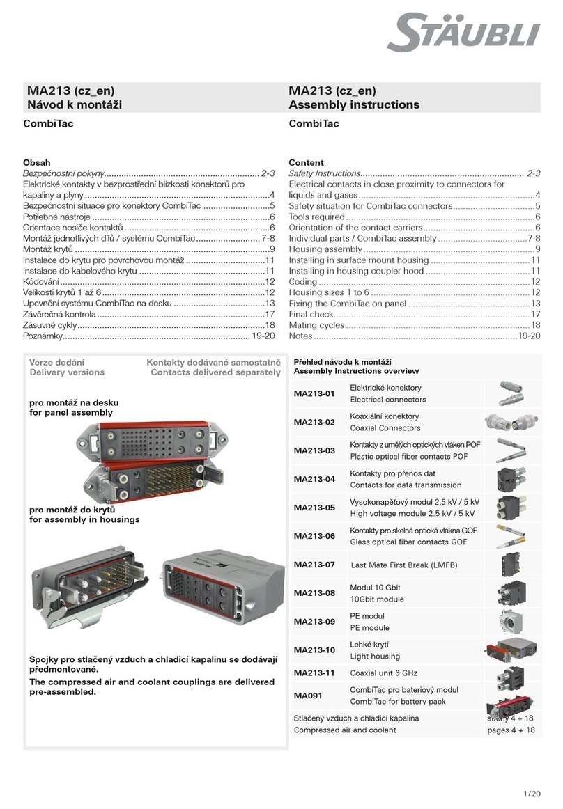
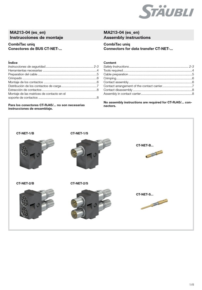
  9. Staubli MA711 User manual

Staubli MA711 User manual

1 / 4
PV-SVK4
32.0717
PV-BVK4
32.0716
MA000 (de_en)
Montageanleitung
MA000 (de_en)
Assembly instructions
MA711 (pl_en)
Instrukcje montażu
MA711 (pl_en)
Assembly instructions
Przewód PV/przedłużenie kabla MC4/MC4-Evo 2 PV cable lead/cable extension MC4/MC4-Evo 2
Spis treści
Instrukcje bezpieczeństwa �����������������������������������������������������������2
Wymagane narzędzia ������������������������������������������������������������������3
Łączenie i rozłączanie ������������������������������������������������������������������3
Uwagi dotyczące instalacji�����������������������������������������������������������4
Content
Safety Instructions �����������������������������������������������������������������������2
Required tools �����������������������������������������������������������������������������3
Mating and disconnecting������������������������������������������������������������3
Notes on installation ��������������������������������������������������������������������4
Zaślepki uszczelniające/Sealing caps
2 / 4
Instrukcje bezpieczeństwa Safety instructions
Znaczenie instrukcji montażu
NIEPRZESTRZEGANIE instrukcji montażu i instrukcji dotyczą-
cych bezpieczeństwa może spowodować obrażenia zagrażające
życiu w wyniku porażenia prądem, łuku elektrycznego, pożaru
lub awarii systemu�
•Postępuj zgodnie z całością instrukcji montażu�
•Użytkuj i instaluj produkt wyłącznie zgodnie z niniejszą instruk-
cją montażu�
•Bezpiecznie przechowuj instrukcję montażu i przekaż ją kolej-
nym użytkownikom�
Importance of the assembly instructions
NOT following the assembly and safety instructions could result
in life-threatening injuries due to electric shock, electric arcs, fire,
or failure of the system�
•Follow the entire assembly instructions�
•Use and install the product only according to this assembly
instructions�
•Safely store the assembly instructions and pass them on to
subsequent users�
Przeznaczenie
Kabel podłączeniowy PV DC zamontowany po jednej lub po obu
stronach, ze złączem MC4 lub MC4-Evo 2, przeznaczony do
instalacji lub przygotowany do dalszego montażu�
Intended use
PV DC connection cable assembled on one or both sides
with MC4 or MC4-Evo 2, for installation or prepared for further
assembly�
Wymagania dotyczące personelu
Montaż, instalację i uruchomienie systemu może przeprowadzić
wyłącznie elektryk lub osoba przeszkolona w zakresie elektryki�
•Elektryk to osoba z odpowiednim przeszkoleniem zawodo-
wym, wiedzą i doświadczeniem do identyfikowania i unikania
zagrożeń, jakie może spowodować energia elektryczna� Elek-
tryk potrafi dobierać i użytkować odpowiednie środki ochrony
osobistej�
•Osoba przeszkolona w zakresie elektryki to osoba przeszko-
lona lub nadzorowana przez elektryka, która potrafi identyfi-
kować i unikać zagrożeń, jakie może spowodować energia
elektryczna�
Requirements for personnel
Only an electrician or electrically instructed person may assem-
ble, install, and commission the system�
•An electrician is a person with appropriate professional
training, knowledge, and experience to identify and avoid the
dangers that may originate from electricity� An electrician is
able to choose and use suitable personal protective equip-
ment�
•An electrically instructed person is a person who is instructed
or supervised by an electrician and can identify and avoid the
dangers that may originate from electricity�
Wymagania wstępne dotyczące instalacji i
montażu
•NIE WOLNO używać produktu, który jest w oczywisty sposób
uszkodzony�
•Należy używać WYŁĄCZNIE narzędzi i procedur zatwierdzo-
nych przez firmę Stäubli�
•Podczas montażu złącza należy przestrzegać odpowiednich
instrukcji montażu złącza (patrz tabela danych technicznych)�
Prerequisites for installation and assembly
•NEVER use an obviously damaged product�
•ONLY tools and procedures approved by Stäubli shall be
used�
•When mounting a connector, the respective assembly
instructions of the connector (see technical data table) must
be observed�
Łączenie i rozłączanie
Części mogą pozostawać pod napięciem po odizolowaniu lub
rozłączeniu�
•Należy ZAWSZE rozładowywać system fotowoltaiczny przed
łączeniem i rozłączaniem złącz�
•NIE WOLNO rozłączać złącz pod obciążeniem�
•NIE WOLNO łączyć części męskiej lub żeńskiej złącza Stäubli
ze złączami innych producentów�
Mating and disconnecting
Live parts can remain energized after isolation or disconnection�
•ALWAYS de-energize the photovoltaic system before mating
and disconnecting the connectors�
•NEVER disconnect the connectors under load�
•NEVER connect male or female part of Stäubli connector with
connectors of other manufacturers�
NIE należy przerabiać ANI naprawiać elementów
•NIE należy przerabiać elementów�
•Należy wymieniać wadliwe elementy�
Do NOT modify NOR repair component
•Do NOT modify component�
•Replace defective component�
3 / 4
2
3
1
PV-MS-PLS PV-MS
Wymagane narzędzia Required tools
(rys. 1)
PV-MS-PLS Narzędzie do montażu i
odblokowania, 1 zestaw = 2 szt�
Zamówienie nr 32�6058
lub
Zestaw kluczy płaskich PV-MS,
Zamówienie nr 32�6024
(ill. 1)
PV-MS-PLS Assembly and unlocking
tool, 1 set = 2 pcs�
Order No� 32�6058
or
Open-end spanner set PV-MS,
Order No� 32�6024
Łączenie i rozłączanie Mating and disconnecting
Uwaga:
Niezamontowane szybkozłącza
muszą być chronione przed wszelkimi
zanieczyszczeniami za pomocą zaśle-
pek uszczelniających Stäubli�
Note:
Unmated connectors must be pro-
tected from any contamination using
Stäubli sealing caps�
(rys. 2)
Łączenie:
Złączyć szybkozłącze kablowe aż do
usłyszenia „kliknięcia”� Sprawdzić prawi-
dłowość połączenia lekko pociągając za
szybkozłącze (maksymalna siła ciągnię-
cia: 20 N)�
(ill. 2)
Mating:
Mate the cable coupler until a „click“
can be heard� Check correct engage-
ment by lightly pulling on the connector
(maximum pulling force: 20 N)�
Uwaga
Montaż nie do końca zatr-
zaśniętych szybkozłączy jest
niedozwolony, ponieważ może to
doprowadzić do trwałego ugięcia
zatrzasków, a tym samym do po-
tencjalnej utraty funkcji blokującej�
Należy sprawdzić działanie blokady
połączonego szybkozłącza�
Attention
Assembly of not fully engaged
connectors is not permitted as this
could lead to a permanent deflec-
tion of clips and thus to a potential
loss of the locking function�
The engaged connector locking
function has to be verified�
(rys. 3)
Rozłączanie:
Użyć PV-MS-PLS/2 lub PV-MS do
rozłączenia�
(ill. 3)
Disconnecting:
Use PV-MS-PLS/2 or PV-MS to discon-
nect�
Uwaga:
Dane techniczne znajdują się w odpowiedniej instrukcji mon-
tażu szybkozłącza�
MC4: MA231
MC4-Evo 2: MA273, MA298
W przypadku pytań technicznych dotyczących przewodów
stosowanych w tym produkcie, Stäubli uprzejmie prosi klientów
o zapoznanie się z kartą katalogową producenta przewodów�
Note:
For technical data, consult the corresponding connector
assembly instructions�
MC4: MA231
MC4-Evo 2: MA273, MA298
For technical questions regarding the cables used in this pro-
duct, Stäubli kindly asks customers to refer to the data sheet of
the cable manufacturer�
4 / 4
Producent:/Manufacturer:
Stäubli Electrical Connectors AG
Stockbrunnenrain 8
4123 Allschwil/Switzerland
Tel. +41 61 306 55 55
Fax +41 61 306 55 56
mail [email protected]
www.staubli.com/electrical
© by Stäubli Electrical Connectors AG, Switzerland – MA711 – 10.2022, index a Marketing Communications – Zastrzegamy możliwość wprowadzenia zmian/Subject to alterations
Uwagi dotyczące instalacji Notes on installation
Ogólne uwagi dotyczące instalacji
•Niezamontowane szybkozłącza należy chronić przed czynnikami
środowiskowymi (wilgoć, brud, kurz itp�) za pomocą zaślepek
uszczelniających (gniazdo
PV-BVK4, zamówienie nr 32�0716; wtyczka PV-SVK4, zamówie-
nie nr 32�0717)�
•Nie należy łączyć zanieczyszczonych szybkozłączy�
•Szybkozłącza nie mogą mieć kontaktu z żadnymi chemikaliami�
General notes on installation
•Unmated connectors must be protected from environmental
impact (moisture, dirt, dust, etc�) with sealing caps (socket
PV-BVK4, order No� 32�0716; plug PV-SVK4, order No�
32�0717)�
•Do not mate contaminated connectors�
•Connectors must not come into contact with any chemicals�
Prowadzenie kabli
•Ułożenie kabla musi zapewniać minimum 20 mm kabla , który
wychodzi prosto z uszczelnienia kablowego bez zginania i
naprężania� Minimalny promień gięcia - patrz specyfikacja produ-
centa kabla�
•W szczególności należy przestrzegać zaleceń dotyczących zasto-
sowania zgodnie z załącznikiem A normy IEC 62930�
Cable routing
•Cable management must allow a minimum of 20 mm of cable
that exits straight from the cable seal without bending or stress�
Refer to cable manufacturer specification for minimum bending
radius�
•In particular, the application notes according to Annex A of
IEC 62930 must be observed�
Zanieczyszczone/uszkodzone szybkozłącza:
•Nie dopuszczać do zanieczyszczenia szybkozłączy przez czynniki
środowiskowe (np� gleba, woda, owady, kurz)�
•Nie dopuszczać do zanieczyszczenia powierzchni szybkozłącza
(np� naklejki, farba, rurki termokurczliwe)�
•Nie dopuszczać do umieszczania szybkozłączy bezpośrednio na
powierzchni dachowej�
•Nie dopuszczać do umieszczania szybkozłączy w najniższym
punkcie okablowania, gdzie może zbierać się woda�
•Nie dopuszczać do umieszczania szybkozłączy w stojącej
wodzie�
•Nie dopuszczać do montażu opasek kablowych bezpośrednio na
korpusie szybkozłącza�
Contaminated/damaged connectors:
•Do not allow connectors to be contaminated by the environ-
ment (e�g� soil, water, insects, dust)�
•Do not allow the connector to be contaminated on its surface
(e�g� stickers, paint, heat shrink tubing)�
•Do not allow that the connector is directly on the roofing sur-
face�
•Do not allow that the connector is at the lowest point of cabling
where water can collect�
•Do not allow that the connector is in standing water�
•Do not allow cable ties to be mounted directly on the connector
body�
Naprężenia mechaniczne:
•Sprawdzić, czy szybkozłącza nie są narażone na stałe mechan-
iczne obciążenie rozciągające lub wibracje�
•Szybkozłącza nie mogą być poddawane naprężeniom
spowodowanym sposobem prowadzenia kabli�
Mechanical stress:
•Check that the connectors are not subjected to a permanent
mechanical tensile load or vibration�
•Connectors shall not be under strain from cable management�
Min.
20 mm

Other Staubli Cables And Connectors manuals

Staubli MA298 User manual

Staubli

Staubli MA298 User manual

Staubli CombiTac User manual

Staubli

Staubli CombiTac User manual

Staubli CombiTac uniq CT-NET Series User manual

Staubli

Staubli CombiTac uniq CT-NET Series User manual

Staubli CombiTac User manual

Staubli

Staubli CombiTac User manual

Staubli 16BL-CP User manual

Staubli

Staubli 16BL-CP User manual

Staubli MA417-1 User manual

Staubli

Staubli MA417-1 User manual

Staubli PV-ADB4-EVO 2 UR Series User manual

Staubli

Staubli PV-ADB4-EVO 2 UR Series User manual

Staubli PerforMore User manual

Staubli

Staubli PerforMore User manual

Staubli MA273 User manual

Staubli

Staubli MA273 User manual

Staubli PV-ADB4-EVO 2A Series User manual

Staubli

Staubli PV-ADB4-EVO 2A Series User manual

Staubli MC SLS425-SE/M User manual

Staubli

Staubli MC SLS425-SE/M User manual

Staubli MC4-Evo 2 User manual

Staubli

Staubli MC4-Evo 2 User manual

Staubli DuraDock power 550 A User manual

Staubli

Staubli DuraDock power 550 A User manual

Staubli MC4-Evo 2 User manual

Staubli

Staubli MC4-Evo 2 User manual

Staubli CombiTac MA213-11 User manual

Staubli

Staubli CombiTac MA213-11 User manual

Staubli Multi-Contact MA213-03 User manual

Staubli

Staubli Multi-Contact MA213-03 User manual

Staubli CombiTac User manual

Staubli

Staubli CombiTac User manual

Staubli CombiTac MA213-03 User manual

Staubli

Staubli CombiTac MA213-03 User manual

Staubli KBT21/M40 C Series User manual

Staubli

Staubli KBT21/M40 C Series User manual

Staubli 16BL-CP User manual

Staubli

Staubli 16BL-CP User manual

Staubli CombiTac uniq CT-LMFB-B2/0,5-1,5 AU User manual

Staubli

Staubli CombiTac uniq CT-LMFB-B2/0,5-1,5 AU User manual

Staubli PV-KST4 UR Series User manual

Staubli

Staubli PV-KST4 UR Series User manual

Staubli CombiTac MA213-03 User manual

Staubli

Staubli CombiTac MA213-03 User manual

Staubli PV-KST4 UR Series User manual

Staubli

Staubli PV-KST4 UR Series User manual

Popular Cables And Connectors manuals by other brands

Sony RK-SX1 Supplement sheet

Sony

Sony RK-SX1 Supplement sheet

nVent RAYCHEM T-100 manual

nVent RAYCHEM

nVent RAYCHEM T-100 manual

3M 7700 Series Preparation Instructions

3M

3M 7700 Series Preparation Instructions

Philips SWA2724W Specifications

Philips

Philips SWA2724W Specifications

Festo NEBM-SM12G8-E Q5-LE6 Series Instructions & assembly

Festo

Festo NEBM-SM12G8-E Q5-LE6 Series Instructions & assembly

Amphenol PL182X-301-70-G95 Assembly manual

Amphenol

Amphenol PL182X-301-70-G95 Assembly manual

ADTRAN 1442520G1 quick start guide

ADTRAN

ADTRAN 1442520G1 quick start guide

FasTest ICON 60 instructions

FasTest

FasTest ICON 60 instructions

Crestron CBL-USB-RS232KM-6 installation guide

Crestron

Crestron CBL-USB-RS232KM-6 installation guide

GE JXHC1 installation instructions

GE

GE JXHC1 installation instructions

Bayco 800 Series instruction manual

Bayco

Bayco 800 Series instruction manual

HP A3352A - 4 GB Hard Drive installation guide

HP

HP A3352A - 4 GB Hard Drive installation guide

Lindy 43099 user manual

Lindy

Lindy 43099 user manual

Emerson Rosemount 356 Reference manual

Emerson

Emerson Rosemount 356 Reference manual

SIIG AV-GM06B3-S1 manual

SIIG

SIIG AV-GM06B3-S1 manual

NEUTRIK opticalCON HYBRID MED NKO16M-XP-0 Series Cleaning instruction

NEUTRIK

NEUTRIK opticalCON HYBRID MED NKO16M-XP-0 Series Cleaning instruction

Eaton COOPER POWER SERIES Assembly/installation instructions

Eaton

Eaton COOPER POWER SERIES Assembly/installation instructions

Ophit HDMB2 user guide

Ophit

Ophit HDMB2 user guide

manuals.online logo
manuals.online logoBrands
  • About & Mission
  • Contact us
  • Privacy Policy
  • Terms and Conditions

Copyright 2025 Manuals.Online. All Rights Reserved.