6998400030
4
PREVENZIONE CONTRO SHOCK ELETTRICI
Prendere le seguenti precauzioni quando si opera con
un generatore di corrente:
- tenere puliti se stessi ed i propri vestiti.
- non essere a contatto con parti umide e bagnate
quando si opera con il generatore.
- mantenere un isolamento adeguato contro gli shock
elettrici. Se l’operatore deve lavorare in ambiente
umido, dovrà usare estrema cautela, vestire scarpe e
guanti isolanti.
- controllare spesso il cavo di alimentazione della
macchina: dovrà essere privo di danni all’isolante. I
CAVI SCOPERTI SONO PERICOLOSI
Non usare la macchina con un cavo di alimentazione
danneggiato; è necessario sostituirlo
immediatamente.
- se c’è la necessità di aprire la macchina, prima
staccare l’alimentazione. Aspettare 5 minuti per
permettere ai condensatori di scaricarsi. Non
rispettare questa procedura può esporre l’operatore a
pericolosi rischi di shock elettrico.
- non operare mai con il generatore, se la copertura di
protezione non è al suo posto.
- assicurarsi che la connessione di terra del cavo di
alimentazione, sia perfettamente efficiente.
Questo generatore è stato progettato per essere
utilizzato in ambiente professionale ed industriale. Per
altri tipi di applicazione contattare il costruttore. Nel
caso in cui disturbi elettroma netici EMF siano
individuati è responsabilità dell’utilizzatore della
macchina risolvere la situazione con l’assistenza
tecnica del costruttore. È vietato l’utilizzo e
l’avvicinamento alla macchina da parte di persone
portatori di stimolatori elettrici (PAC MAK RS).
DESCRIZIONE GENERALE
Questa nuova serie di generatori a regolazione
elettronica governata da microprocessore,
consente di raggiungere una eccellente qualità di
saldatura, grazie alle avanzate tecnologie
applicate. Il circuito microprocessore controlla ed
ottimizza il trasferimento dell’arco
indipendentemente dalla variazione del carico e
dell’impedenza dei cavi di saldatura. I comandi sul
pannello frontale consentono una facile
programmazione delle sequenze di saldatura in
funzione delle esigenze operative. La tecnologia
inverter usata ha permesso di ottenere:
- generatori con peso e dimensioni estremamente
contenuti;
- ridotto consumo energetico;
- eccellente risposta dinamica;
- fattore di potenza e rendimenti molto alti;
- caratteristiche di saldatura migliori;
- visualizzazione su display dei dati e delle funzioni
impostate.I componenti elettronici sono racchiusi in
una robusta carpenteria facilmente trasportabile e
raffreddati ad aria forzata con ventilatori a basso
livello di rumorosità.
N.B. Il generatore non è adatto per sgelare tubi.
RICEVIMENTO
L’imballo contiene:
- N. 1 generatore
- N. 1 manuale istruzione
- N. 1 kit messa in servizio
- N. 1 connettore
Verificare che siano compresi nell’imballo tutti i
materiali sopra elencati. Avvisare il Vs. distributore se
manca qualcosa. Verificare che il generatore non sia
stato danneggiato durante il trasporto. Se vi è un
danno evidente, vedere la sezione R CLAMI per
istruzioni. Prima di operare con il generatore leggere
attentamente questo manuale di istruzioni.
RECLAMI
Reclami per danne iamento durante il trasporto:
Se la Vs. apparecchiatura viene danneggiata durante
la spedizione, dovete inoltrare un reclamo al Vs.
spedizioniere.
Reclami per merce difettosa: Tutte le
apparecchiature spedite da ST L sono state
sottoposte ad un rigoroso controllo di qualità. Tuttavia
se la Vs. apparecchiatura non dovesse funzionare
correttamente rivolgetevi al Vs. concessionario
autorizzato.
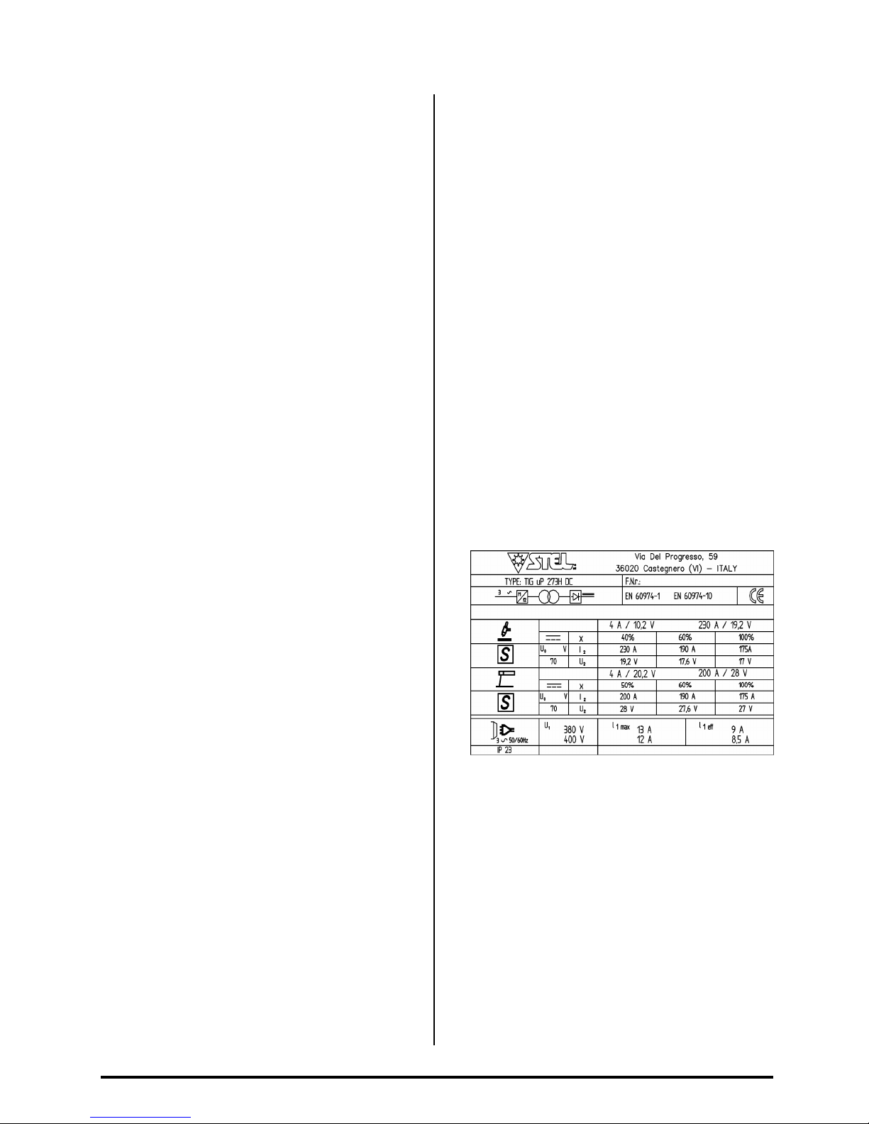
DATI TECNICI
A) ID NTIFICAZION
Nome, indirizzo del costruttore
Tipo generatore
Identificazione riferita al numero di serie
Simbolo del tipo di generatore
Riferimento alla normativa di costruzione
B) DATI DI SALDATURA
Simbolo del processo di lavoro
Simbolo per generatori idonei ad operare in ambiente
a rischio accresciuto di scossa elettrica.
Simbolo della corrente
Tensione assegnata a vuoto (tensione media)
Gamma della corrente
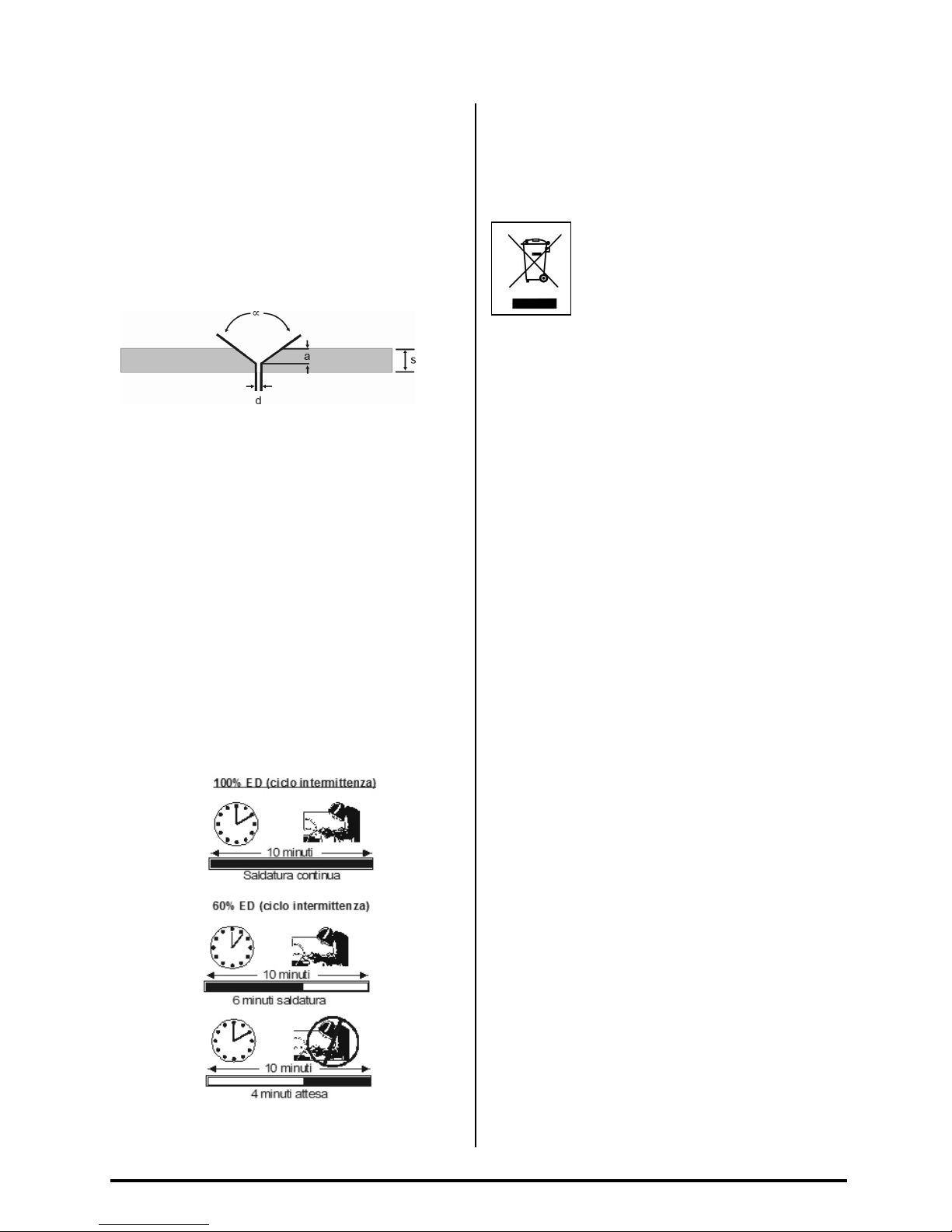
Valori del ciclo di intermittenza (su 10 minuti)
A