INSSCRSP0214
Installer’s guIde
SCRSP SERIES - SPLICE PLATE
For further information or to consult this guide online, please visit our web site:www.stelpro.com
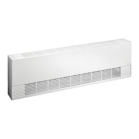
Prior to installing the two radiators, the end covers facing each other need to be removed from both units. Install them both according to the instructions
described in the SCR User’s Guide included with the units.
Make sure to leave a space between the two units to allow for metal expansion during the heating cycle. See THE MINIMUM SPACE TABLE below for
the minimum required space depending on the model. To simplify the task of making the electrical connections in the junction boxes, you may temporarily
position one unit further away; and once the connections are made, to disengage only the bottom clips of the wall brackets of that unit, slide the unit to
the proper spacing between the units and re-engage the clips.
POWER SUPPLY CONNECTION AT ONE OF THE EXTREMITIES
To do so, you must proceed with the electrical connections shown in FIGURE 1 (see next page) for both the center connections and for the
extremity connections, and plan for a spacing between the units according to the MINIMUM SPACE TABLE.
POWER SUPPLY CONNECTION IN THE MIDDLE
If you choose making the power supply connections in the middle of both units, it must be done according to FIGURE 2 (see next page) and
proceed with one of the following methods depending on the choice of knockout hole.
1 - USING THE KNOCKOUT HOLE AT THE BACK PART OF THE SPLICE PLATE
Space the units equally or larger than the minimum listed in the MINIMUM SPACE TABLE, keep in mind this space must be at least equivalent to the
plate, pass the cable through it and fasten it in place. Make the electrical connections according to FIGURE 2 (see next page).
2 - USING A KNOCKOUT HOLE FROM ONE OF THE RADIATORS’ JUNCTION BOX
Space the units equally or larger than the minimum listed in the MINIMUM SPACE TABLE, make sure it is large enough to allow the insertion of the cable
CHOICE OF ELECTRICAL POWER SUPPLY CONNECTIONS
minimum space TaBLe
minimum space BeTWeen TWO iDenTicaL RaDiaTORs insTaLLeD siDe BY siDe
mODeL # pOWeR - WaTTs minimum space - inch (mm)
SCR045 450 7/16 (11)
SCR060 600 9/16 (14)
SCR075 750 11/16 (17)
SCR090 900 3/4 (19)
SCR105 1050 7/8 (22)
SCR120 1200 1 (25)
SCR150 1500 1-1/8 (29)
Before installing and operating this product, the user and/or installer must
read, understand and follow these instructions and keep them handy for
future reference. If these instructions are not followed, the warranty will be
considered null and void and the manufacturer deems no further responsibility
for this product.
The following instructions must be adhered to in order to avoid personal and
serious injuries, property damages and potentially fatal electric shocks.
Switch off the power at the circuit breaker/fuse before installing, repairing and
cleaning the unit.
Make sure the unit is appropriate for the intended use (if needed, refer to the
product catalogue or a representative).
WARNING
