Safety Technology International
2306 Airport Road • Waterford, Michigan 48327-1209
Phone: 248-673-9898 • Fax: 248-673-1246
Web: www.sti-usa.com
Safety Technology International Ltd
Taylor House • 34 Sherwood Road • Bromsgrove
Worcestershire • B60 3DR • England
Tel: +44 (0)1527 520 999 • Fax: +44 (0)1527 501 999
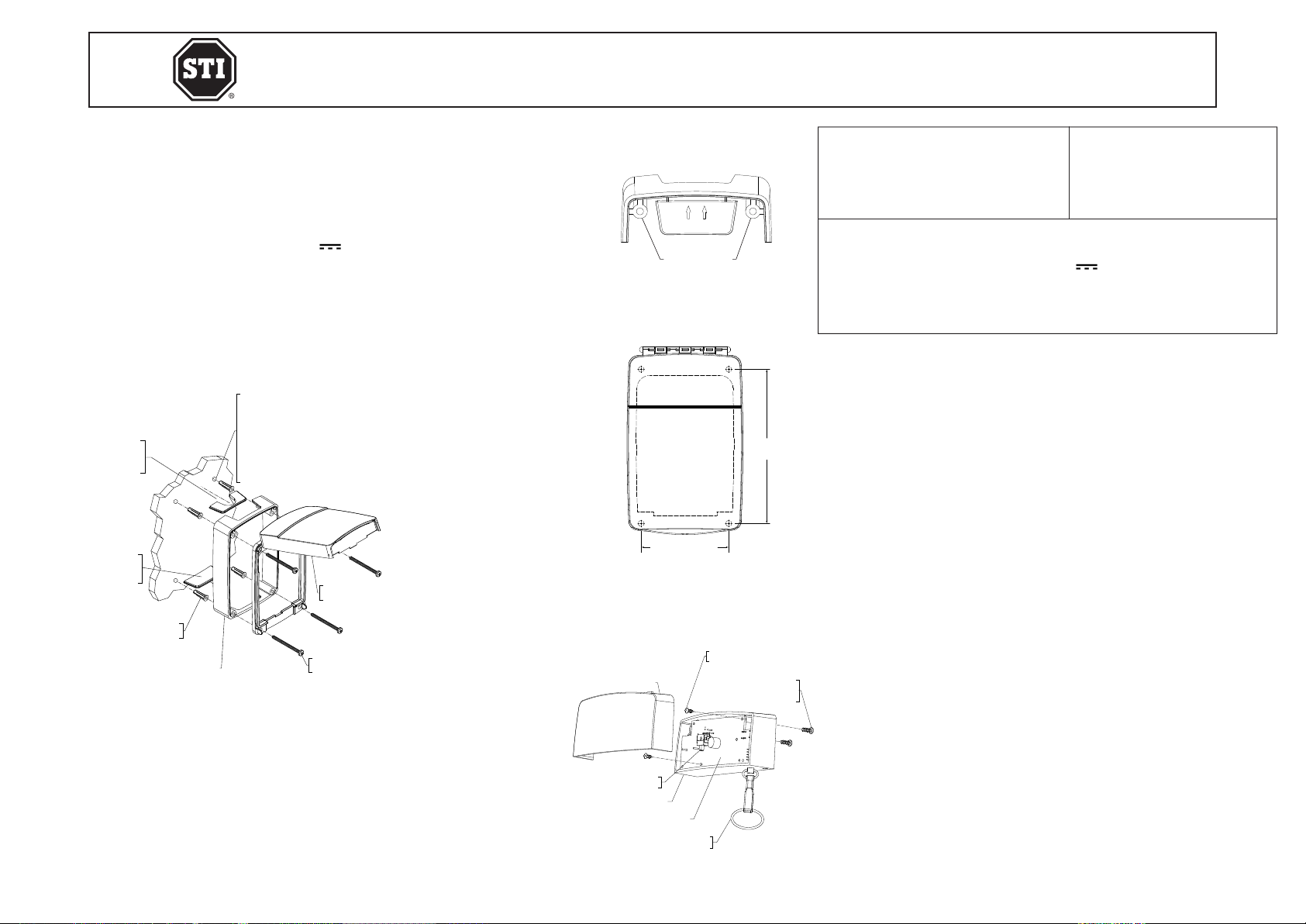
SERVICE PIN
(1) PROVIDED
#2 x .25 in. SMS
M277 BATTERY COVER
CR123A BATTERY
Fig. 6
Optional Wireless Transmitter Version
1. The supervised wireless sounder version is capable of transmitting a 433MHz alert to any
STI Receiver (range up to 1000 ft.)
2. When lifting the cover, the wireless Euro Stopper® will send an alert to an STI receiver. For
enrolling this device, refer to STI receiver installation instructions.
3. On closing the cover, the wireless Euro Stopper® will send a restore signal to an STI receiver.
4. CAUTION: This device will transmit an alert even with the service pin in place.
Replacing the Battery
1. The Euro Stopper® sounder will emit an audible beep when the battery becomes low.
2. Lift cover and insert the service pin.
3. Using a small Phillips screwdriver, remove the battery cover.
4. Replace 3V CR123A Lithium battery, taking care to observe the polarity as marked.
5. Reassemble the battery cover and screws, then remove the service pin to arm.
Optional Break Seals
1. There are two (2) locking tabs, one (1) on each side of the frame. Choose which side the
break seal is to be located, close the cover and carefully drill a 3mm (.118”) diameter hole
at the witness point.
2. Once the device is ready to be protected, remove the service pin (if applicable), close the
cover and lock the break seal in place.
A
A
BB 104mm
(4.11 in.)
185mm
(7.30 in.)
135mm
(5.30 in.)
32mm
(1.25 in.)
37mm
(1.45 in.)
94mm
(3.70 in.)
114mm
(4.50 in.)
C
C
DD 104mm
(4.11 in.)
135mm
(5.30 in.)
185mm
(7.30 in.)
32mm
(1.26 in.)
58mm
(2.30 in.)
63mm
(2.48 in.)
68mm
(2.68 in.)
94mm
(3.70 in.)
115mm
(4.53 in.)
C
C
DD 135mm
(5.30 in.)
185mm
(7.30 in.)
1.4mm
(4.11 in.)
50mm
(1.97 in.)
76mm
(3.00 in.)
81mm
(3.20 in.)
86mm
(3.39 in.)
94mm
(3.70 in.)
116mm
(14.56 in.)
104mm
(4.11 in.)
185mm
(7.30 in.)
135mm
(5.30 in.)
32mm
(1.25 in.)
37mm
(1.45 in.)
94mm
(3.70 in.)
114mm
(4.50 in.)
C
C
DD 104mm
(4.11 in.)
135mm
(5.30 in.)
185mm
(7.30 in.)
32mm
(1.26 in.)
58mm
(2.30 in.)
63mm
(2.48 in.)
68mm
(2.68 in.)
94mm
(3.70 in.)
115mm
(4.53 in.)
C
C
DD 135mm
(5.30 in.)
185mm
(7.30 in.)
1.4mm
(4.11 in.)
50mm
(1.97 in.)
76mm
(3.00 in.)
81mm
(3.20 in.)
86mm
(3.39 in.)
94mm
(3.70 in.)
116mm
(14.56 in.)
A
A
BB 104mm
(4.11 in.)
185mm
(7.30 in.)
135mm
(5.30 in.)
32mm
(1.25 in.)
37mm
(1.45 in.)
94mm
(3.70 in.)
114mm
(4.50 in.)
C
C
DD 104mm
(4.11 in.)
135mm
(5.30 in.)
185mm
(7.30 in.)
32mm
(1.26 in.)
58mm
(2.30 in.)
63mm
(2.48 in.)
68mm
(2.68 in.)
94mm
(3.70 in.)
115mm
(4.53 in.)
C
C
DD 135mm
(5.30 in.)
185mm
(7.30 in.)
1.4mm
(4.11 in.)
50mm
(1.97 in.)
76mm
(3.00 in.)
81mm
(3.20 in.)
86mm
(3.39 in.)
94mm
(3.70 in.)
116mm
(14.56 in.)
A
A
BB 104mm
(4.11 in.)
185mm
(7.30 in.)
135mm
(5.30 in.)
32mm
(1.25 in.)
37mm
(1.45 in.)
94mm
(3.70 in.)
114mm
(4.50 in.)
C
C
DD
104mm
(4.11 in.)
135mm
(5.30 in.)
185mm
(7.30 in.)
32mm
(1.26 in.)
58mm
(2.30 in.)
63mm
(2.48 in.)
68mm
(2.68 in.)
94mm
(3.70 in.)
115mm
(4.53 in.)
C
C
DD 135mm
(5.30 in.)
185mm
(7.30 in.)
1.4mm
(4.11 in.)
50mm
(1.97 in.)
76mm
(3.00 in.)
81mm
(3.20 in.)
86mm
(3.39 in.)
94mm
(3.70 in.)
116mm
(14.56 in.)
A
A
BB 104mm
(4.11 in.)
185mm
(7.30 in.)
135mm
(5.30 in.)
32mm
(1.25 in.)
37mm
(1.45 in.)
94mm
(3.70 in.)
114mm
(4.50 in.)
C
C
DD 104mm
(4.11 in.)
135mm
(5.30 in.)
185mm
(7.30 in.)
32mm
(1.26 in.)
58mm
(2.30 in.)
63mm
(2.48 in.)
68mm
(2.68 in.)
94mm
(3.70 in.)
115mm
(4.53 in.)
C
C
DD 135mm
(5.30 in.)
185mm
(7.30 in.)
1.4mm
(4.11 in.)
50mm
(1.97 in.)
76mm
(3.00 in.)
81mm
(3.20 in.)
86mm
(3.39 in.)
94mm
(3.70 in.)
116mm
(14.56 in.)
A
A
BB 104mm
(4.11 in.)
185mm
(7.30 in.)
135mm
(5.30 in.)
32mm
(1.25 in.)
37mm
(1.45 in.)
94mm
(3.70 in.)
114mm
(4.50 in.)
C
C
DD 104mm
(4.11 in.)
135mm
(5.30 in.)
185mm
(7.30 in.)
32mm
(1.26 in.)
58mm
(2.30 in.)
63mm
(2.48 in.)
68mm
(2.68 in.)
94mm
(3.70 in.)
115mm
(4.53 in.)
C
C
DD
135mm
(5.30 in.)
185mm
(7.30 in.)
1.4mm
(4.11 in.)
50mm
(1.97 in.)
76mm
(3.00 in.)
81mm
(3.20 in.)
86mm
(3.39 in.)
94mm
(3.70 in.)
116mm
(14.56 in.)
Caring for Polycarbonate
Rinse with warm water to remove dust and dirt. Wash with soap or mild detergent. Concentrated solutions and those including
(but not limited to) alkalis, strong acids, ethers, amines, aromatic hydrocarbons and alcohols can cause considerable harm to
this product. Rinse once more then dry with a soft cloth or chamois. DO NOT use sharp objects that may scratch the surface.
Exercise caution when using water inside the enclosure and ensure the unit is completely dry inside before reassembling.
IMPORTANT NOTICE
Changes or modications not expressly approved by the manufacturer could void the user’s authority to operate the equipment.
This device complies with Industry Canada license-exempt RSS standard(s). Operation is subject to the following two
conditions: (1) this device may not cause interference, and (2) this device must accept any interference, including interference
that may cause undesired operation of the device.
Le présent appareil est conforme aux CNR d’Industrie Canada applicables aux appareils radio exempts de licence. L’exploitation
est autorisée aux deux conditions suivantes : (1) l’appareil ne doit pas produire de brouillage, et (2) l’utilisateur de l’appareil
doit accepter tout brouillage radioélectrique subi, même si le brouillage est susceptible d’en compromettre le fonctionnement.
Contains FCC ID: TXL34080 Model: STI-34080
Fig. 7
DIMENSIONAL DRAWINGS
Surface Mount 32mmFlush Mount Surface Mount 50mm
OPTIONAL 5 PIN
CONNECTOR
WIRE HARNESS
12/24 VDC
SERVICE PIN
#2 x .25 SMS
(2) PROVIDED
34080
PCB SOUNDER
#4 x .312
HI-LOW SCREW
(2) PROVIDED M276 HORN CASE
DRILL
3/16 in. (5mm)
HOLE THRU
Fig. 5
END
VIEW
SIDE
VIEW
IC: 6335A-34080 15000 series
2013_12
Warranty
Three year guarantee against breakage of polycarbonate in normal use (one year on electro mechanical and electronic
components). Electronic warranty form at www.sti-usa.com/wc14.
WARNING: This product can expose you to chemicals including Bisphenol A, which is known to the State of California to
cause reproductive harm and Dichloromethane, which is known to the State of California to cause cancer.
For more information go to www.P65Warnings.ca.gov.