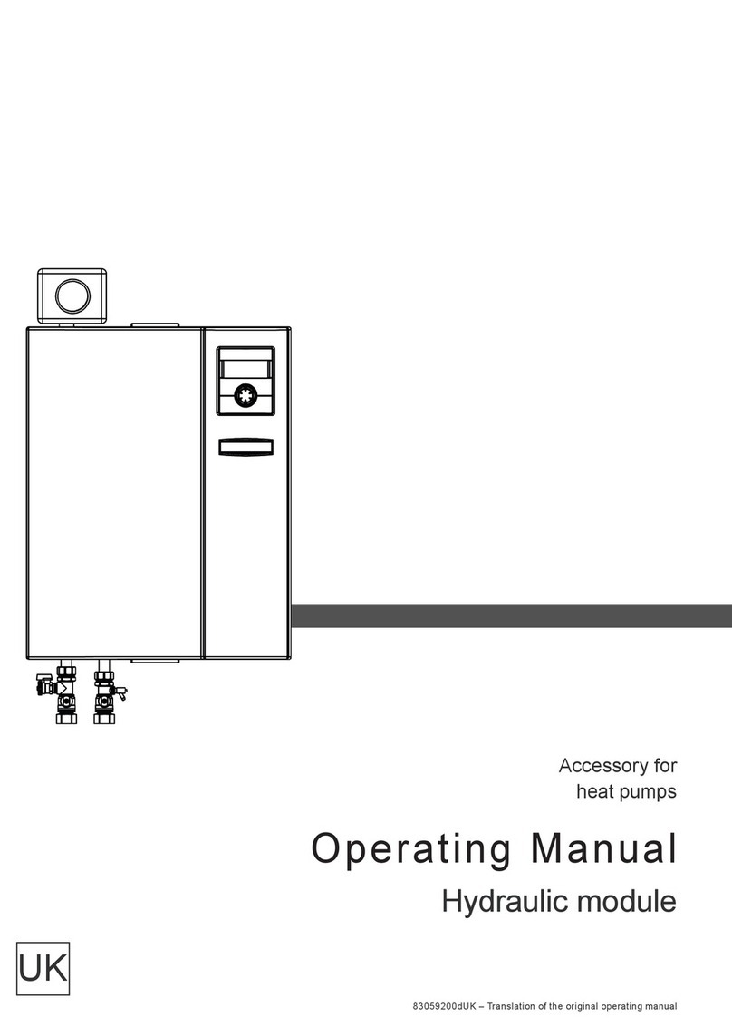
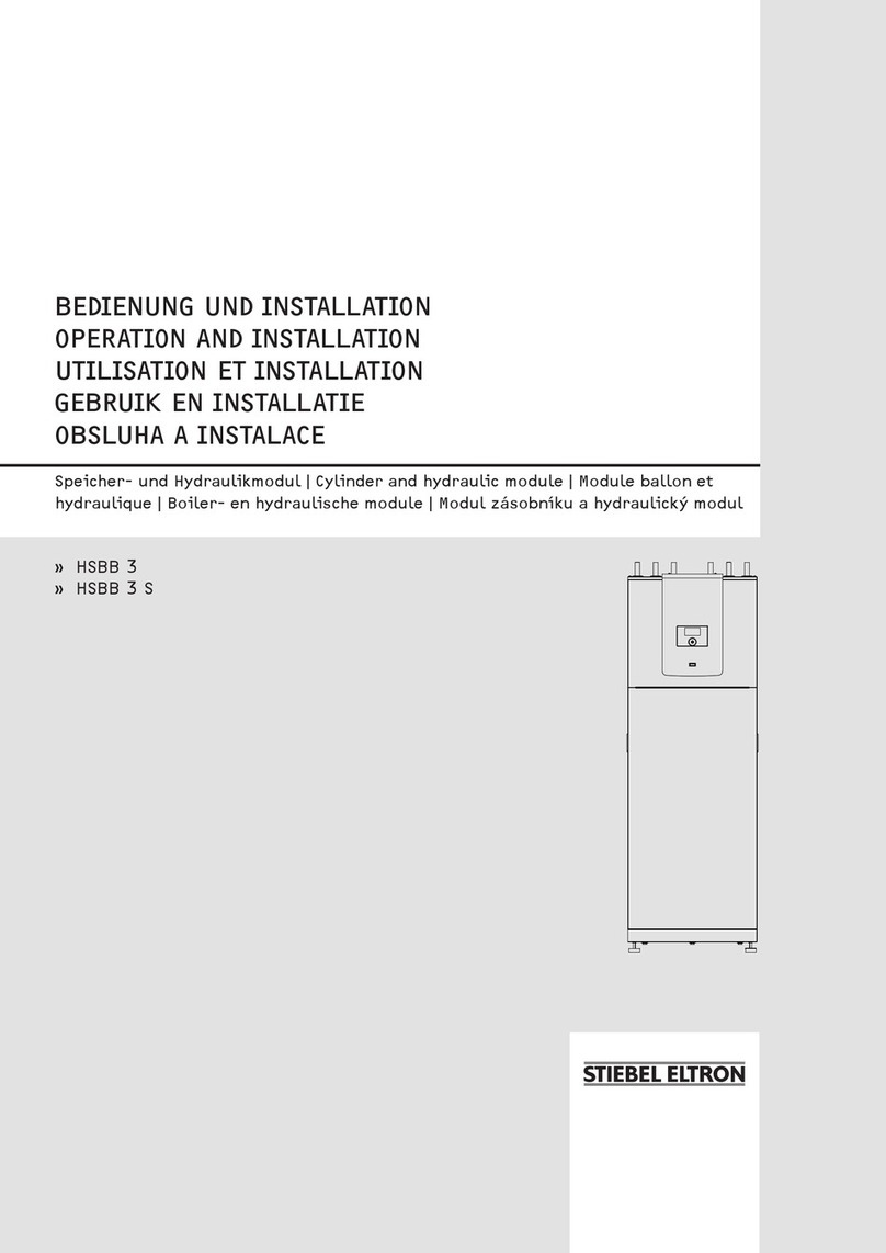
STIEBEL ELTRON WPIC-B User manual

.CeC&eC.CZ`<<`.HC
HTV`.HCC.CZ`<<`.HC
e`.<.Z`.HC`.CZ`<<`.HC
%şĉ÷ŒêĒĉńăĒ®şùÏţļ<şÏŒ |ńń¼ļé ļă¼ĤşăĤ¼%şĉŒêĒĉăĒ®şù¼ÏĒļ|êļńĒşļ¼ä¼|Œ
ĤşăĤBĒ®şù¼ĒăĤ|ŒĤĒşļêĉńŒ|ùù|ŒêĒĉêĉŒ½ļê¼¼şļ¼®¼ĤĒăĤ¼ä|ù¼şļ|êļ¼|ş
á T.é

Ĝƃ T.é ĪZ`.<é<`VHCĪHB
HC`C`ZHTV`.HC
&CV<.C%HVB`.HC
HC`C`Z
OPERATION ________________________________________________________ 10
1. General information _______________________________________ 10
1.1 Further applicable documents _______________________________ 10
1.2 Other symbols in this documentation ______________________ 10
1.3 Units of measurement _________________________________________ 10
2. Safety________________________________________________________ 11
2.1 Intended use_____________________________________________________ 11
2.2 General safety instructions ___________________________________ 11
2.3 Test symbols _____________________________________________________ 11
INSTALLATION _____________________________________________________ 11
3. Safety________________________________________________________ 11
3.1 General safety instructions ___________________________________11
3.2 Regulations, standards and instructions___________________ 11
3.3 Standard delivery_______________________________________________ 11
4. Preparing for installation _________________________________ 11
4.1 General information____________________________________________ 11
4.2 Fitting the function module __________________________________ 12
4.3 Opening the function module ________________________________ 12
4.4 Hydraulic connection __________________________________________ 12
4.5 Safety valve ______________________________________________________ 13
4.6 Connecting electrical cables__________________________________ 13
4.7 Closing the function module _________________________________ 13
4.8 Connecting the air hoses______________________________________ 13
5. Specification ________________________________________________ 13
5.1 Data table ________________________________________________________ 13
5.2 Connections and dimensions_________________________________ 14
5.3 System example_________________________________________________ 15
WARRANTY
ENVIRONNEMENT AND RECYCLING
HTV`.HC
1. General information
The chapter “Operation” is intended for appliance users and hea-
ting contractors.
The chapter “Installation” is intended for heating contractors.
Note
Read these instructions carefully before using the ap-
pliance and retain them for future reference.
Pass on the instructions to a new user if required.
1.1 Further applicable documents
Operating and installation instructions of the heat pump
WPL E or WPL basic
Operating and installation instructions of the WPMII
heat pump manager
Operating and installation instructions of the hydraulic
module HSBB
Operating and installation instructions of all other com-
ponents in the system
1.2 Other symbols in this documentation
Note
General information is identified by the symbol shown
on the left.
f Read these texts carefully.
ZźăĒù
Material losses
Appliance disposal
f This symbol indicates that you have to do something. The ac-
tion you need to take is described step by step.
1.3 Units of measurement
Note
All measurements are given in mm unless stated othe-
rwise.

ENGLISH
HTV`.HC.CZ`<<`.HC
Z%`t
ĪZ`.<é<`VHCĪHB T.éĜĜ
2. Safety
2.1 Intended use
The WPIC-B function module may only be operated in conjunction
with a WPL13E or WPL13basic which has been installed indoors
and the function moduleHSBB.
Any other use beyond that described shall be deemed inappro-
priate. Observation of these instructions and of instructions for any
accessories used is also part of the correct use of this appliance.
2.2 General safety instructions
Observe the following safety instructions and regulations.
- The installation of the heating circuit must only be carried
out by a qualified contractor or by our customer service
engineers.
- The authorised contractor is responsible for adherence to
all currently applicable instructions during installation and
commissioning.
- Operate the appliance only when fully installed and with all
safety equipment fitted.
2.3 Test symbols
See type plate on the appliance.
.CZ`<<`.HC
3. Safety
Only a qualified contractor should carry out installation, commis-
sioning, maintenance and repair of the appliance.
3.1 General safety instructions
We guarantee trouble-free operation and operational reliability
only if the original accessories and spare parts intended for the
appliance are used.
3.2 Regulations, standards and instructions
Note
Observe all applicable national and regional regulations
and instructions.
3.3 Standard delivery
Delivered with the function module:
- 1 x heat pump casing components
- 2 x air hose
- 2 x pressure hose
- 1 x outside temperature sensor AFS 2
- 2 x immersion sensor TF 6
4. Preparing for installation
4.1 General information
Note
The heat pump with function module is designed for ins-
tallation in interiors, except in wet areas.
By installing the supplied pressure hoses to connect the function
module and the heat pump, you do not need to install any addi-
tional pressure hoses externally as anti-vibration mounts.
Pre-assembled elements, comprising an air hose and wall connec-
ting plates, connect the function module to the air intake and
discharge in the wall.
f When positioning the heat pump, please observe the wall
clearances specified (see chapter “Specification / Dimensions
and connections” in the operating and installation instruc-
tions of the heat pump).

Ĝŝ T.é ĪZ`.<é<`VHCĪHB
.CZ`<<`.HC
TVTV.C&%HV.CZ`<<`.HC
4.2 Fitting the function module
26_03_01_1792
f Place the function module on the heat pump and secure with
two screws.
Affix the type plate supplied to top front right-hand side of the
side panel of the function module where it will be clearly visible.
4.3 Opening the function module
26_03_01_1008
f Remove the locking screw.
f Pull the lever forwards and the left-hand flap will open.
f Open the right-hand flap by pulling it firmly.
4.4 Hydraulic connection
Connect the function module to the heat pump using the supplied
pressure hoses.
1
2
26_03_01_1813
1 Flow pressure hose
2 Return pressure hose
f Check the firm seat and tightness of the push-fit connector on
the safety assembly.
Push-fit connectors are fitted on the function module flow and
return connections to make the connection to the hydraulic mo-
dule HSBB.
The push-fit connectors are equipped with a retainer with stainless
steel serrations and an O-ring for sealing. In addition, they are
designed with the “twist and lock” function. By simply turning the
screw cap manually, the pipe is secured in the connector, and the
O-ring is pushed against the pipe to seal it.
Risk of damage
Support sleeves are required when using plastic pipes.
Making the connection
The connector must be in its relaxed position before the pipe is
inserted. In this position, there is a small gap between the screw
cap and connector body.

ĪZ`.<é<`VHCĪHB T.éĜŗ
ENGLISH
.CZ`<<`.HC
ZT.%.`.HC
26_03_01_0693
1
1 Gap between screw cap and connector body
f Trim the pipe to the required length using only a pipe cutter.
f Push the burr-free pipe past the O-ring into the connector as
far as it will go.
f Tighten the screw cap fully to the casing. This presses the
O-ring against the pipe and locks the connector.
26_03_01_0693
Pipe Ø 28 mm
Depth of insertion A 44 mm
Releasing the connection
f Undo the screw cap until a small gap appears.
f Press the retainer back with your fingers and hold on to it.
The pipe can now be pulled out again.
26_03_01_0693
4.5 Safety valve
f Size the drain so that water can drain off unimpeded when
the safety valve is fully opened.
f Fit the discharge pipe of the safety assembly with a constant
slope.
f Ensure that the discharge aperture of the safety valve is open
to the outside.
4.6 Connecting electrical cables
f Route the electrical cables for connecting the heat pump
through the entries provided (see chapter “Specification /
Dimensions and connections”).
4.7 Closing the function module
26_03_01_1816
f Close the flaps and secure the lever with the locking screw to
prevent unauthorised opening of the function module.
4.8 Connecting the air hoses
f Attach the pre-assembled air hoses to the function module
using the wing nuts contained in the pack.
f Mark the fixing holes on the outside wall using the drilling
template provided.
f Use rawl plugs and screws that are suitable for the wall
structure to attach the air hoses.
5. Specification
5.1 Data table
T.é
232144
Dimensions
Height mm 637
Width mm 1240
Depth mm 800
Weights
Weight kg 80
Connections
Connection 28 mm

ĜÔ T.é ĪZ`.<é<`VHCĪHB
.CZ`<<`.HC
ZT.%.`.HC
5.2 Connections and dimensions
E
F
J
J
H
H
D0000021976
T.
b01 Entry electrical cables
c11 Safety assembly
e01 Heating flow Plug-in connection 28 mm
e02 Heating return Plug-in connection 28 mm
g01 Air intake
g02 Air discharge

ĪZ`.<é<`VHCĪHB T.éĜÑ
ENGLISH
.CZ`<<`.HC
ZT.%.`.HC
5.3 System example
1
1b
1a
c01
c06
1 Heat pump
1a Function module WPIC-B
1b Hydraulic module HSBB
2a Outside temperature sensor
3 Circulation pump
5 Safety valve
6 Expansion vessel
10 Drain & fill valve
13 Mixing valve
28 Safety assembly
31 Overflow valve
36 Protective control thermostat for underfloor heating
systems
c01 Cold water inlet
c06 DHW outlet
Warranty
The warranty conditions of our German companies do not
apply to appliances acquired outside of Germany. In countries
where our subsidiaries sell our products, it is increasingly the
case that warranties can only be issued by those subsidiaries.
Such warranties are only granted if the subsidiary has issued
its own terms of warranty. No other warranty will be granted.
We shall not provide any warranty for appliances acquired in
countries where we have no subsidiary to sell our products.
This will not aect warranties issued by any importers.
Environment and recycling
We would ask you to help protect the environment. After use,
dispose of the various materials in accordance with national
regulations.

CH`.xCŨŨCH`Z
ŝŝ T.é ĪZ`.<é<`VHCĪHB

CH`.xCŨŨCH`Z
ĪZ`.<é<`VHCĪHB T.éŝŗ

Deutschland
STIEBEL ELTRON GmbH & Co. KG
Dr.-Stiebel-Straße | 37603 Holzminden
Tel. 05531 702-0 | Fax 05531 702-480
www.stiebel-eltron.de
Verkauf Tel. 0180 3 700705* | Fax 0180 3 702015* | info-c[email protected]
Kundendienst Tel. 0180 3 702020* | Fax 0180 3 702025* | kund[email protected]
Tel. 05531 702-90015
Ersatzteilverkauf Tel. 0180 3 702030* | Fax 0180 3 702035* | [email protected]
Tel. 05531 702-90050
Vertriebszentren Tel. 0180 3 702010* | Fax 0180 3 702004*
* 0,09 €/min bei Anrufen aus dem deutschen Festnetz. Maximal 0,42 €/min bei Anrufen aus Mobilfunknetzen.
Irrtum und technische Änderungen vorbehalten! | Subject to errors and technical changes! | Sous réserve
d‘erreurs et de modifications techniques! | Onder voorbehoud van vergissingen en technische wijzigingen! |
Salvo error o modificación técnica! | Excepto erro ou alteração técnica | Zastrzeżone zmian
y
techniczne i
ewentualne błędy | Omyly a technické změny jsou vyhrazeny! | A muszaki változtatások és tévedések jogát
fenntartjuk! | Отсутствие ошибок не гарантируется. Возможны технические изменения. | Chyby a
technické zmeny sú vyhradené! Stand 8734
Austria
STIEBEL ELTRON Ges.m.b.H.
Eferdinger Str. 73 | 4600 Wels
Tel. 07242 47367-0 | Fax 07242 47367-42
www.stiebel-eltron.at
Belgium
STIEBEL ELTRON bvba/sprl
't Hofveld 6 - D1 | 1702 Groot-Bijgaarden
Tel. 02 42322-22 | Fax 02 42322-12
www.stiebel-eltron.be
Czech Republic
STIEBEL ELTRON spol. s r.o.
K Hájům 946 | 155 00 Praha 5 - Stodůlky
Tel. 251116-111 | Fax 235512-122
www.stiebel-eltron.cz
Denmark
Pettinaroli A/S
Mandal Allé 21 | 5500 Middelfart
Tel. 06341 666-6 | Fax 06341 666-0
www.stiebel-eltron.dk
Finland
Insinööritoimisto Olli Andersson Oy
Kapinakuja 1 | 04600 Mäntsälä
Tel. 020 720-9988 | Fax 020 720-9989
www.stiebel-eltron.fi
France
STIEBEL ELTRON SAS
7-9, rue des Selliers
B.P 85107 | 57073 Metz-Cédex 3
Tel. 0387 7438-88 | Fax 0387 7468-26
www.stiebel-eltron.fr
Hungary
STIEBEL ELTRON Kft.
Pacsirtamező u. 41 | 1036 Budapest
Tel. 01 250-6055 | Fax 01 368-8097
www.stiebel-eltron.hu
Japan
NIHON STIEBEL Co. Ltd.
Kowa Kawasaki Nishiguchi Building 8F
66-2 Horikawa-Cho
Saiwai-Ku | 212-0013 Kawasaki
Tel. 044 540-3200 | Fax 044 540-3210
www.nihonstiebel.co.jp
Netherlands
STIEBEL ELTRON Nederland B.V.
Daviottenweg 36
5222 BH 's-Hertogenbosch
Tel. 073 623-0000 | Fax 073 623-1141
www.stiebel-eltron.nl
Poland
STIEBEL ELTRON Polska Sp. z o.o.
ul. Działkowa 2 | 02-234 Warszawa
Tel. 022 60920-30 | Fax 022 60920-29
www.stiebel-eltron.pl
Russia
STIEBEL ELTRON LLC RUSSIA
Urzhumskaya street 4,
building 2 | 129343 Moscow
Tel. 0495 7753889 | Fax 0495 7753887
www.stiebel-eltron.ru
Slovakia
TATRAMAT - ohrievače vody, s.r.o.
Hlavná 1 | 058 01 Poprad
Tel. 052 7127-125 | Fax 052 7127-148
www.stiebel-eltron.sk
Switzerland
STIEBEL ELTRON AG
Netzibodenstr. 23 c | 4133 Pratteln
Tel. 061 81693-33 | Fax 061 81693-44
www.stiebel-eltron.ch
Thailand
STIEBEL ELTRON Asia Ltd.
469 Moo 2 Tambol Klong-Jik
Amphur Bangpa-In | 13160 Ayutthaya
Tel. 035 220088 | Fax 035 221188
www.stiebeleltronasia.com
United Kingdom and Ireland
STIEBEL ELTRON UK Ltd.
Unit 12 Stadium Court
Stadium Road | CH62 3RP Bromborough
Tel. 0151 346-2300 | Fax 0151 334-2913
www.stiebel-eltron.co.uk
United States of America
STIEBEL ELTRON, Inc.
17 West Street | 01088 West Hatfield MA
Tel. 0413 247-3380 | Fax 0413 247-3369
www.stiebel-eltron-usa.com
A 297209-36602-8730
.,'%.%
Table of contents
Other STIEBEL ELTRON Heat Pump Accessories manuals

STIEBEL ELTRON
STIEBEL ELTRON SK 2 User manual

STIEBEL ELTRON
STIEBEL ELTRON SB-VTI 100 Instruction Manual

STIEBEL ELTRON
STIEBEL ELTRON GWS 1 User manual

STIEBEL ELTRON
STIEBEL ELTRON SBB 300-1 Plus Instruction Manual

STIEBEL ELTRON
STIEBEL ELTRON WK 1 User manual

STIEBEL ELTRON
STIEBEL ELTRON WPSB 308 E User manual

STIEBEL ELTRON
STIEBEL ELTRON HSBB 3 Instruction Manual

STIEBEL ELTRON
STIEBEL ELTRON SBB 301 WP User manual

STIEBEL ELTRON
STIEBEL ELTRON WPSF User manual

STIEBEL ELTRON
STIEBEL ELTRON Scale TAC-ler Plus Series User manual