GWS |21
ENGLISH
INSTALLATION
Commissioning
Required water quality
Common problems when using groundwater as a heat source
include:
- Erosion of heat exchanger and water supply lines.
- Heat exchanger corrosion.
- Sludge contamination or blockages in heat exchanger and
supply lines.
- Sedimentation (blocking) of the return well.
To prevent such problems, the quality of the groundwater used
as heat source must meet the following standards:
- The water must not contain any matter which might
settle.
- Never use surface water or saline water.
- The iron and manganese content must be less than 0.5
mg/l.
In pertinent individual cases, e.g. wells near salt mining areas
or regions with a great prevalence of livestock, the following
water content needs to be taken into consideration:
- Chloride < 300 mg/l
- Chlorine < 0.5 mg/l
If one of the specied limits is exceeded, operation of the
groundwater station is not permissible.
To prevent blockage of the heat exchanger caused by solid
particles transported with the groundwater (sand, ne sludge,
etc.), install a suitable dirt lter with a mesh size of 0.6mm on
site at the heat source ow. You can obtain a suitable dirt lter
via your contractor or from us as a spare part. Install appropri-
ate pre-lters and settlement basins if higher levels of solid
particles are transported with the groundwater.
After lling, vent the heat source system.
Adjust the heat source ow rate so that the brine ow rate at
the brine/water heat pump always corresponds to the required
values.
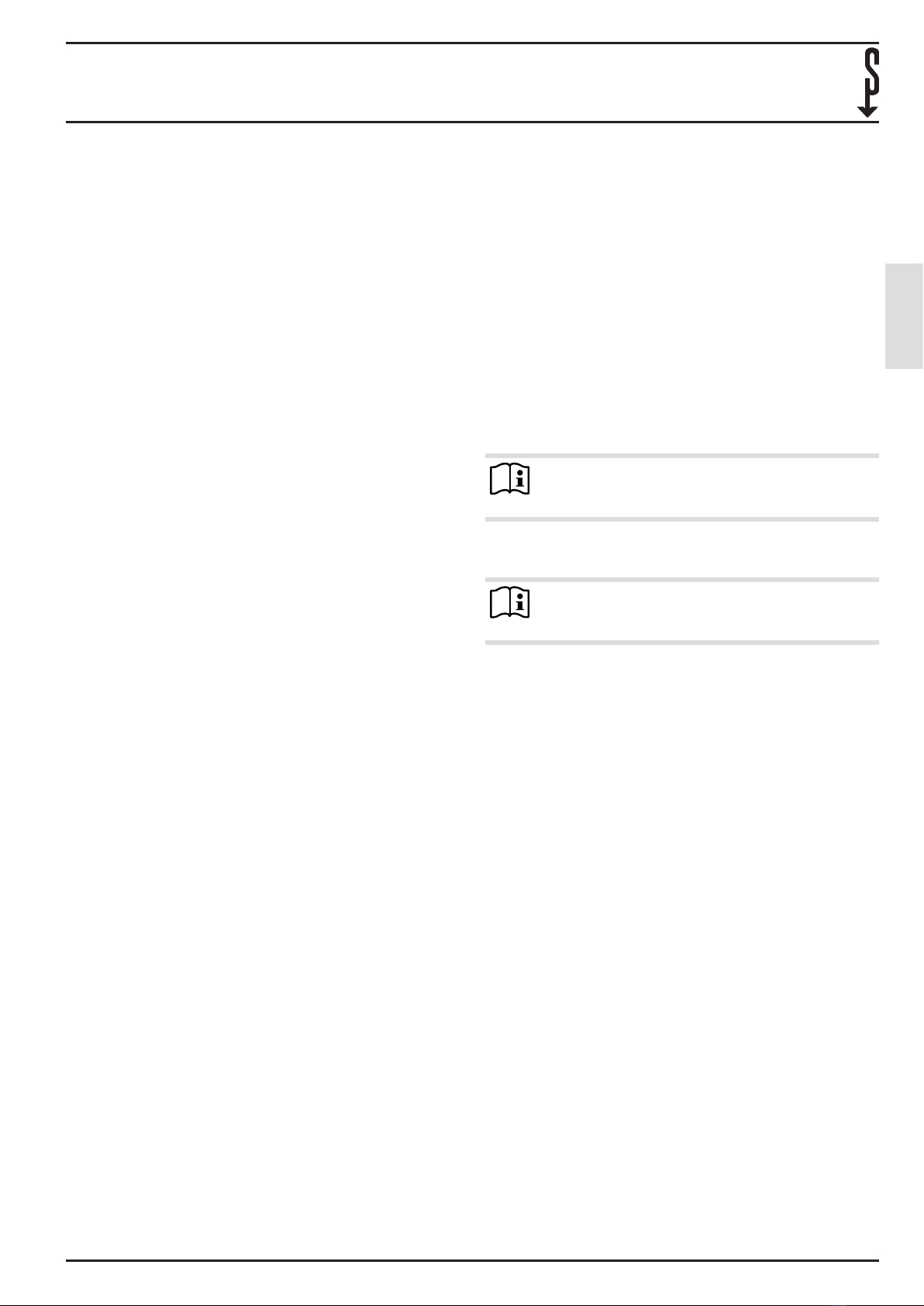
Note
Read and observe the operating and installation in-
structions for the brine/water heat pump and the di-
agrams in chapter “Specication”.
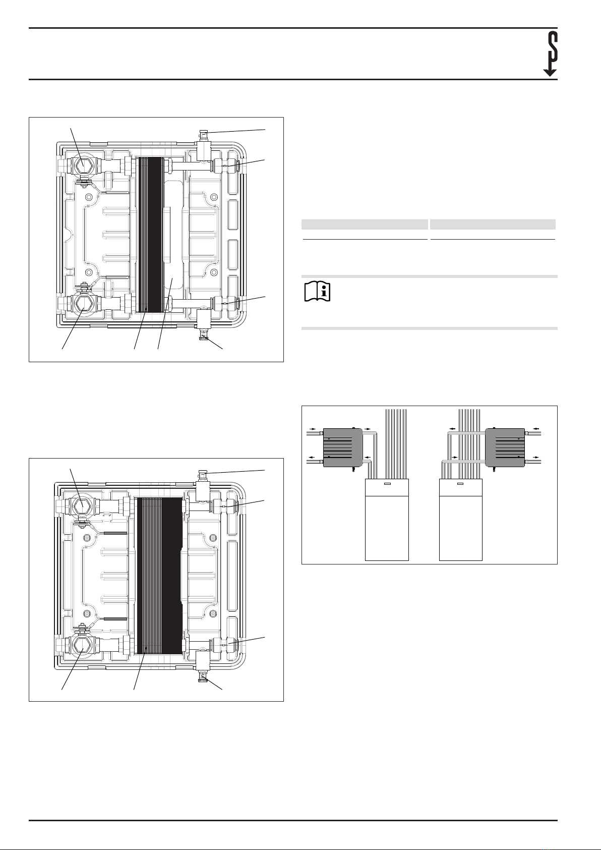
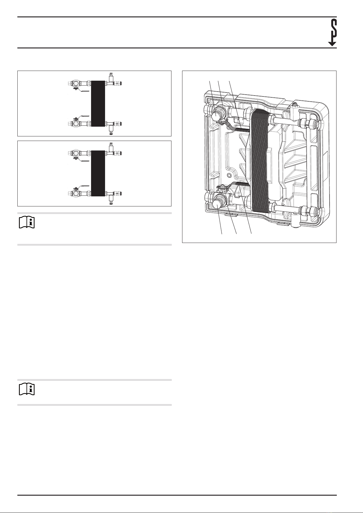
3.4 Insulation
To avoid condensate and therefore damage to the heat source
system and the brine circuit, insulate them with diusion-proof
material.
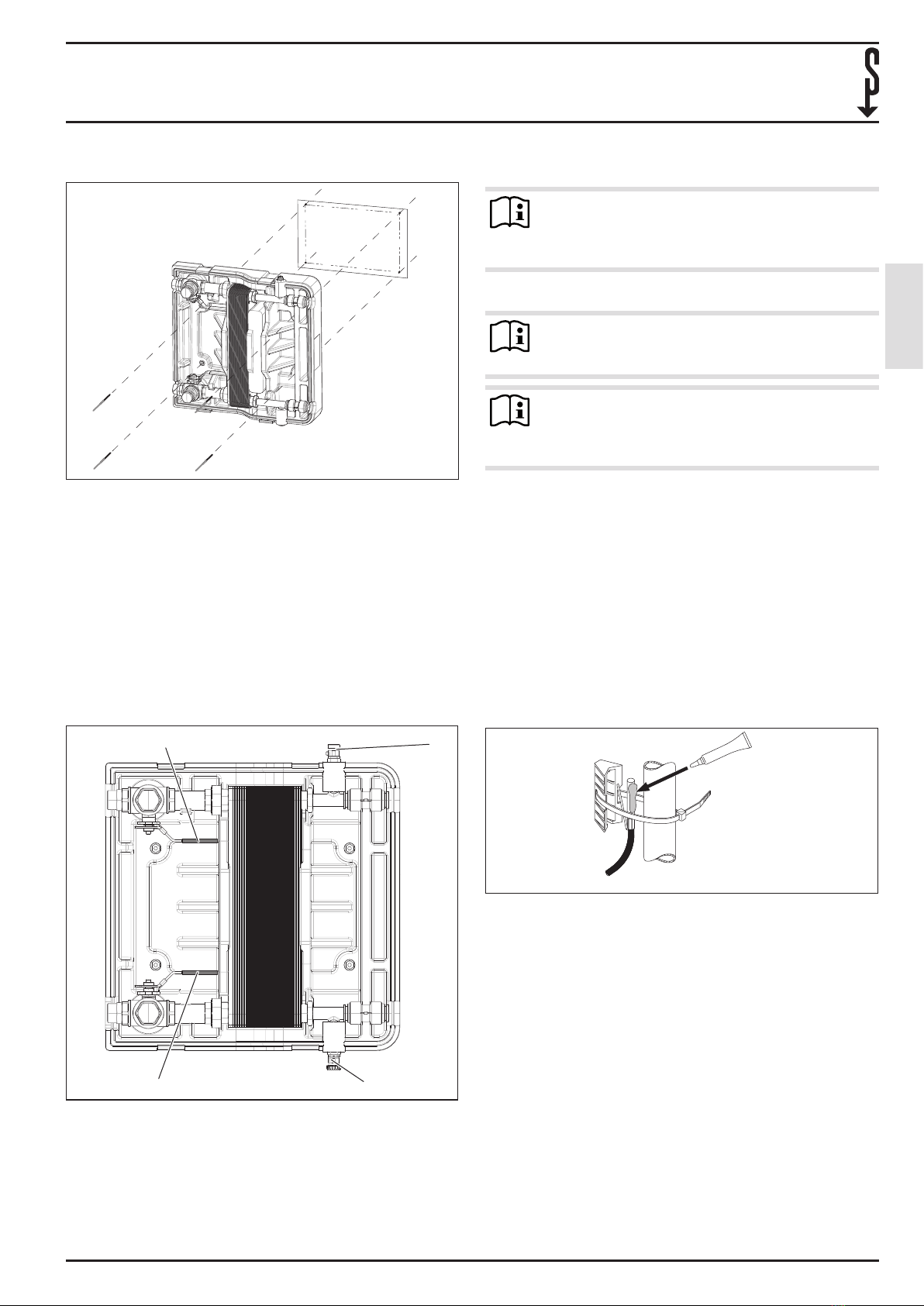
Also insulate the drain & ll valve, the air vent valve and
the brine pressure switch.
26�03�14�0101�
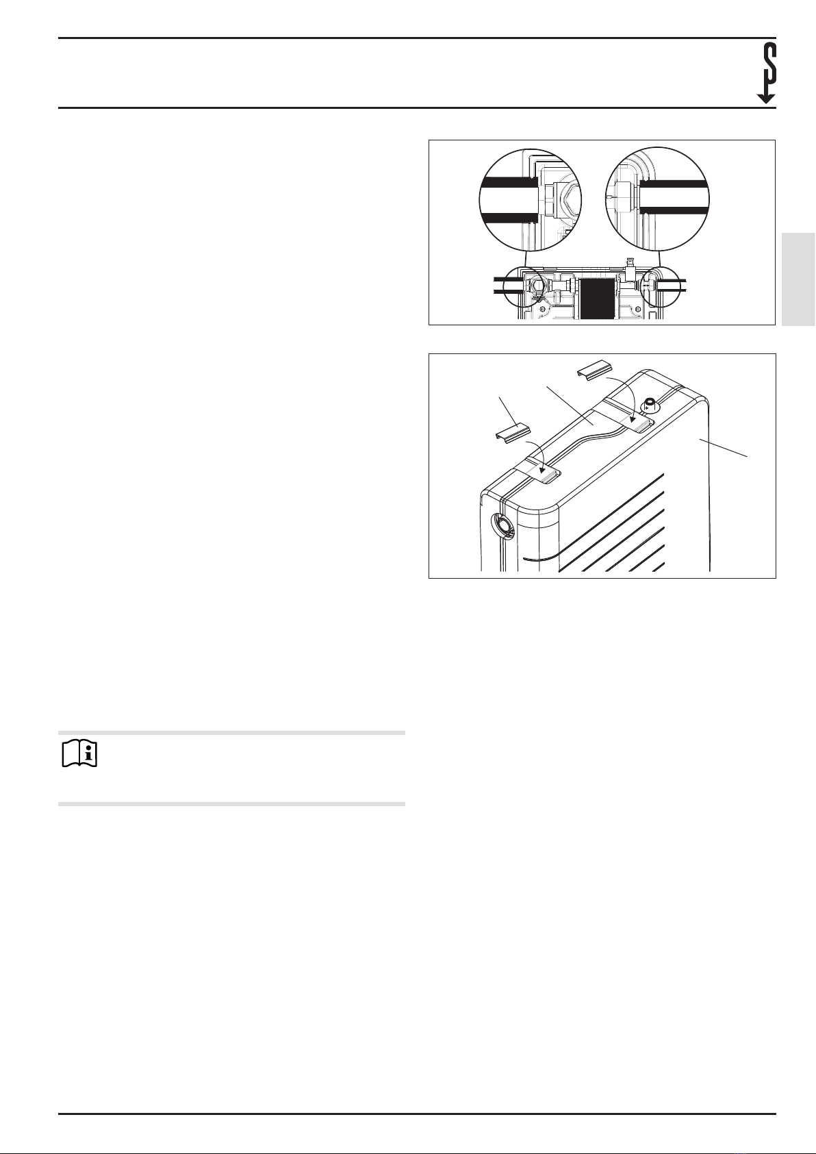
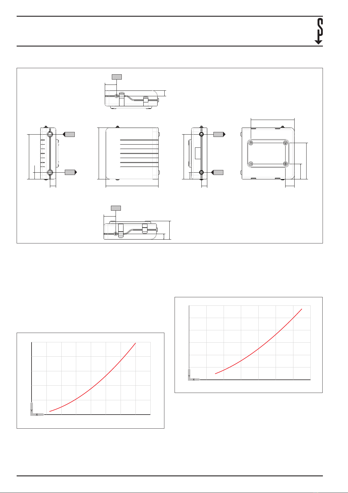
Fit the insulation hoses as shown in the diagram above.
1
3
2
26�03�14�0098�
1 Lower shell
2 Upper shell
3 Clip
After insulation, t the upper shell on the groundwater
station.
Secure the upper shell to the lower shell using the clips
provided.
4. Commissioning
Move the levers of the 3-way ball valves to the throughput
position.
Check the system pressure in the brine circuit. The system
must have overpressure of at least 0.1 MPa.
With the “Relay test” parameter on the heat pump man-
ager, check the functioning of the well and brine circuit
pump.
Read the heat source temperature o the heat pump
manager under the “Info temperatures” parameter and
check the plausibility of this value.
Check the “SOURCE MIN” (minimum source temperature)
and “SOURCE” settings on the heat pump manager.
Commission the brine/water heat pump.
The groundwater station temperature dierential between
the heat source inlet and the heat source outlet should be no
higher than 3K.
The temperature dierential ∆ϕ1 in the heat source circuit
must be greater than the temperature dierential ∆ϕ2 in the
brine circuit.