STONEFLY DR365V-HA User manual

16-bay 3U HA RAID Array
Setup Guide
DR365V-HA
Veeam-Ready Backup &
Disaster Recovery Appliance
© 2023 StoneFly, Inc. | All Rights Reserved
2x 2U Backup Controllers

This Page is intentionally left blank.

Copyright © 2006-2023 StoneFly, Inc.
All rights are reserved. No part of this document may be photocopied or reproduced without
the prior written consent of StoneFly.
The information contained in this document is subject to change without notice. StoneFly
shall not be liable for errors contained herein or for consequential damages in connection
with the furnishing, performance, or use of this material.
StoneFly, the StoneFly logo, Storage Concentrator, Integrated Storage Concentrator, ISC,
Modular Storage Concentrator, StoneFly Backup Advantage, StoneFusion, StoneFly
Replicator CDP, ValueSAN, Unified Scale Out, USO, Super Scale Out, SSO, Twin Scale
Out, TSO, Unified Storage & Server, USS, Unified Deduplicated Storage, UDS, Unified
Encrypted Storage, UES, OptiSAN, StoneFly Voyager, DR365, DR365 Fusion, StoneFly
Mirroring, Storage Concentrator Virtual Machine, SCVM, Software-Defined Unified
Storage, SDUS, and StoneFly Cloud Drive are property of StoneFly, Inc.
Other brands and their products are trademarks or registered trademarks of their respective
holders.
Last update: 03/2023

DR365V-HA Setup Guide Table of Contents
© 2023 StoneFly, Inc. | All rights reserved. 3 |P a g e
Contents
Introduction.............................................................................................................................5
1.1.1 Icons ................................................................................................................................7
1.1.2 System diagram and description........................................................................................7
1.1.3 Product Registration.........................................................................................................8
1.1.4 Contacting StoneFly for Help ...........................................................................................8
2.1 Mounting the Equipment........................................................................................................10
2.1.1 Required Networks and Static IP Addresses....................................................................10
2.1.2 2U Backup Controller Rack Installation Instructions.......................................................11
2.1.3 HA RAID Storage Expansion Array / HA Expansion Unit Rack Installation Instructions 15
2.2 Safety Reminders ...............................................................................................................20
3.1 Cabling the Equipment.................................................................................................................23
4.1 HA RAID Storage Expansion Array IP Address Configuration...............................................28
4.1.1 Serial port setup..............................................................................................................29
4.1.2 Web GUI IP Address setup.............................................................................................33
4.2 Configuring IPMI KVM.........................................................................................................36
Accessing the IPMI Interface .........................................................................................................39
4.3 VMware Management Network Configuration.......................................................................42
4.4 Steps to Configure SCVM Management Port (VMware).........................................................49
4.5 Hyper-V Management Network Configuration.......................................................................53
4.6 Steps to Configure SCVM Management Port (Hyper-V).........................................................57
4.7 Configuring the SCVM ..........................................................................................................61
4.8 Configuring the Veeam Management VM ..............................................................................68
4.8.1 Assigning a Static IP Address to the Veeam Management VM........................................68
4.8.2 Enabling RDP on the Veeam Management VM ..............................................................72
4.8.3 Accessing Windows Server hosting Veeam ....................................................................74

DR365V-HA Setup Guide Introduction
© 2023 StoneFly, Inc. | All rights reserved. 4 |P a g e
Chapter-1: Introduction

DR365V-HA Setup Guide Introduction
© 2023 StoneFly, Inc. | All rights reserved. 5 |P a g e
Introduction
This document is aimed for system administrators who would like to know how to get started
with StoneFly DR365V-HA Appliance. It describes initial steps for launching the appliance.
The StoneFly DR365-HA combines high availability with backup and disaster recovery to ensure
hyper-availability for enterprise mission-critical workloads. Leverage StoneFly’s battle-tested
technology and consolidate all of your server and backup systems into one easy to manage,
simple-to-use and highly available appliance.
This guide gives an overview of the product, rack mounting instructions and initial installation
procedure. Information for using the features of the StoneFusion software is found in the Storage
Concentrator User Guide on the included CD.
StoneFly Resource Library:
https://stonefly.com/resources
The StoneFly SCVM™ Webpage:
https://stonefly.com/hyper-converged/scvm-virtual-storage-appliance
Veeam Backup & Replication User Guide for VMware:
https://helpcenter.veeam.com/docs/backup/vsphere/overview.html?ver=95u4
Veeam Backup & Replication User Guide for Hyper-V:
https://helpcenter.veeam.com/docs/backup/hyperv/overview.html?ver=95u4
Each StoneFly DR365V-HA comes preconfigured with VMware vSphere or Microsoft Hyper-V
hypervisor on each cluster node, a StoneFly SCVM™ Virtual Storage Controller on each cluster
node, and Veeam’s Backup and Replication Software running on a second VM. Additional
Virtual Machines can be installed on the DR365V-HA as needed as long as adequate processing
cores and system memory are available to support those VMs. Contact your StoneFly sales
representative for details.
StoneFly DR365V-HA is made of three or more parts: Two Hyperconverged StoneFly
Storage Concentrator (SC) appliances and one or more StoneFly HA RAID Storage
Expansion Arrays.
StoneFly DR365V-HA supports the following backup controller appliances:
Dual 1U Backup Controller, Quad 12Gb SAS Connection
Dual 2U Backup Controller, Quad 12Gb SAS Connection
Dual 1U Backup Controller, Quad 16Gb FC Connection
Dual 2U Backup Controller, Quad 16Gb FC Connection

DR365V-HA Setup Guide Introduction
© 2023 StoneFly, Inc. | All rights reserved. 6 |P a g e
DR365V-HA 2U Backup Controller (with bezel)
The StoneFly DR365V-HA can be configured with the following StoneFly HA RAID
Storage Expansion Arrays:
12-bay / 2U 12Gb SAS HA RAID Storage Expansion Array (12 x 3.5” SAS drives)
16-bay / 3U 12Gb SAS HA RAID Storage Expansion Array (16 x 3.5” SAS drives)
24-bay / 4U 12Gb SAS HA RAID Storage Expansion Array (24 x 3.5” SAS drives)
24-bay / 2U 12Gb SAS HA RAID Storage Expansion Array (24 x 2.5” SAS drives)
12-bay / 2U 16Gb FC HA RAID Storage Expansion Array (12 x 3.5” SAS drives)
16-bay / 3U 16Gb FC HA RAID Storage Expansion Array (16 x 3.5” SAS drives)
24-bay / 4U 16Gb FC HA RAID Storage Expansion Array (24 x 3.5” SAS drives)
24-bay / 2U 16Gb FC HA RAID Storage Expansion Array (24 x 2.5” SAS drives)
StoneFly HA RAID Storage Expansion Arrays can be connected to the following StoneFly
HA Expansion Units:
12-bay / 2U 12Gb SAS HA Expansion Unit (12 x 3.5” SAS drives)
16-bay / 3U 12Gb SAS HA Expansion Unit (16 x 3.5” SAS drives)
24-bay / 2U 12Gb SAS HA Expansion Unit (24 x 2.5” SAS drives)
60-bay / 4U 12Gb SAS HA Expansion Unit (60 x 3.5” SAS drives – one drawer)
60-bay / 4U 12Gb SAS HA Expansion Unit (60 x 3.5” SAS drives – two drawers)
24-bay / 4U 12Gb SAS HA RAID Storage Expansion Array
DR365V-HA Setup Guide Introduction
© 2023 StoneFly, Inc. | All rights reserved. 7 |P a g e
1.1.1 Icons
Icon
Type
Description
Note
Special instructions or information
Warning
Risk of system damage or a loss of data
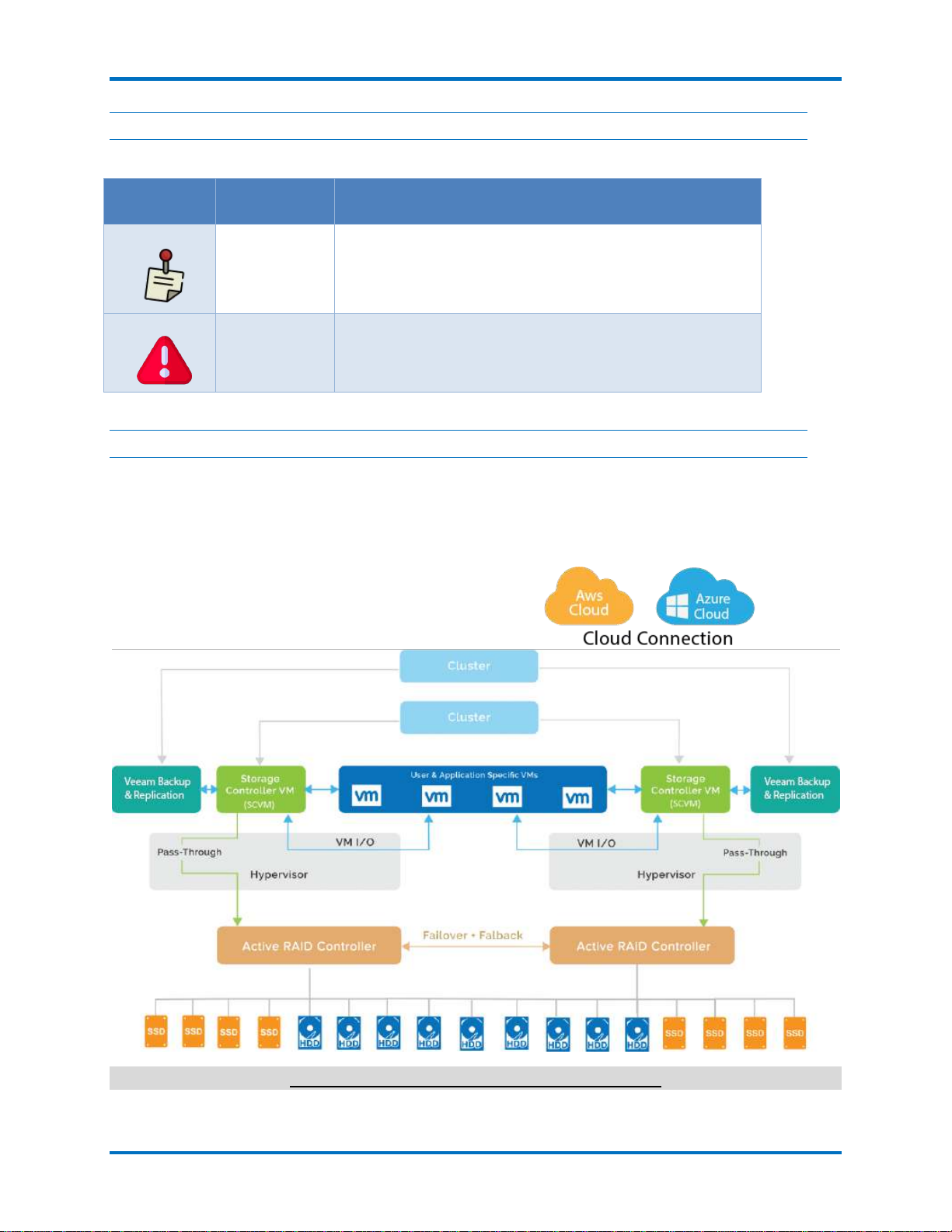
1.1.2 System diagram and description
The figure below is a network interconnection diagram for the StoneFly DR365V-HA appliance.
It consists of two StoneFly hyperconverged Storage Concentrator (SC) cluster nodes. The
diagram also includes shared a StoneFly HA RAID Storage Expansion Array with dual active-
active hardware RAID controllers with failover and failback.
StoneFly DR365V-HA Network Interconnection

DR365V-HA Setup Guide Introduction
© 2023 StoneFly, Inc. | All rights reserved. 8 |P a g e
1.1.3 Product Registration
To initiate StoneFly customer service for your product, you must first register the appliance.
Send us an email with the following information:
Model Number: ______________ ____________________
Serial Numbers: Your appliance serial numbers start with D500 and are located on the rear of
each chassis.
1.1.4 Contacting StoneFly for Help
Please have the following information available when contacting StoneFly technical support for
assistance:
Model Number: _____________________ ___________________________
Serial Number(s): D500 _ _ _ _
Software Version: ____________________ __________________________
Initiators: ___________________ ____________________
Storage: ___________________ _____________________
To contact StoneFly call 510.265.1616 (Select support from the menu). Our technical support is
available 24 hours a day and 7 days a week. You can also contact us via email at
support@stonefly.com

© 2023 StoneFly, Inc. | All rights reserved. 9 |P a g e
Chapter-2: Initial Installation

DR365V-HA Setup Guide Initial Installation
© 2023 StoneFly, Inc. | All rights reserved. 10 |P a g e
2.1 Mounting the Equipment
The DR365V-HA appliance is comprised of at least two StoneFly hyperconverged SCs and one
HA RAID Storage Expansion Array. Depending on which model you purchased, the
interconnects between the SCs and the HA RAID Storage Expansion Array will be either SAS or
FC. The SAS cables connecting the SCs with the HA RAID Storage Expansion Arrays and
optional HA Expansion Units are short. When mounting the units, you should make sure that the
units are rack mounted close to each other.
The following installation process describes how you can mount two 1U SC appliances and a
standard 2U HA RAID Storage Expansion Array.
To ensure proper installation and functionality of the StoneFly appliance, please observe the
following warnings:
Wear an anti-static wristband before and during the installation procedure.
It is recommended to plug the system into two different power sources (eg. into a power
outlet and another into a UPS).
Ensure the rack which the enclosure will be mounted onto has proper grounding and
over-current protection.
Do not obstruct ventilation openings; provide 20cm of free space at the front and back of
the enclosure for air circulation; keep the ambient temperature below 35 degrees Celsius.
2.1.1 Required Networks and Static IP Addresses
Following is a list of static IPs & networks required for a DR365V-HA setup (with VMware ESXi).
Networks Required for a DR365V-HA Setup (with VMware ESXi):
Management Network (1Gbps or 10Gbps)
Data Network (10Gbps or Higher)
Note: Both of the above listed networks should be separate i.e. they should be on different VLANs and
should have different IP Ranges.
List Of Static IPs for a DR365V-HA Setup (with VMware ESXi):
Head-Unit/Compute-Node-1 (Backup
Controller):
Static IP on the Management Network
for the IPMI Port
Static IP on the Management Network
for the Management Port
Static IP on the Data Network for the
Data Port
Head-Unit/Compute-Node-2 (Backup
Controller):
Static IP on the Management Network
for the IPMI Port
Static IP on the Management Network
for the Management Port
Static IP on the Data Network for the
Data Port
DR365V-HA Setup Guide Initial Installation
© 2023 StoneFly, Inc. | All rights reserved. 11 |P a g e
RAID Array (Shared Storage):
Static IP on the Management Network
for the Management Port
SCVM HA Cluster:
Static IP on the Management Network
for the Cluster iSCSI Management IP
Alias (Floating IP)
Static IP on the Data Network for the
Cluster iSCSI Data IP Alias (Floating
IP)
Static IP on the Management Network
for the Cluster NAS Management IP
Alias (Floating IP)
Static IP on the Data Network for the
Cluster NAS Data IP Alias (Floating IP)
ESXi Failover HA Cluster:
Static IP on the Management Network
(Floating IP)
Static IP on the Data Network (Floating
IP)
High Availability (HA) VMs:
Static IP on the Management Network
for the Veeam Windows VM
Static IP on the Data Network for the
Veeam Windows VM
Static IP on the Management Network
for the File Level Immutable Gateway
Static IP on the Data Network for the
File Level Immutable Gateway
Number of IPs Required on the Management and Data Networks for a DR365V-HA Setup (with
VMware ESXi)
Required Management Network IPs: 10
Required Data Network IPs: 7
2.1.2 2U Backup Controller Rack Installation Instructions
This section provides information on installing the server into a rack unit with the rack rails provided.
There are a variety of rack units on the market, so the assembly procedure may differ slightly. Refer to the
installation instructions that came with your rack.
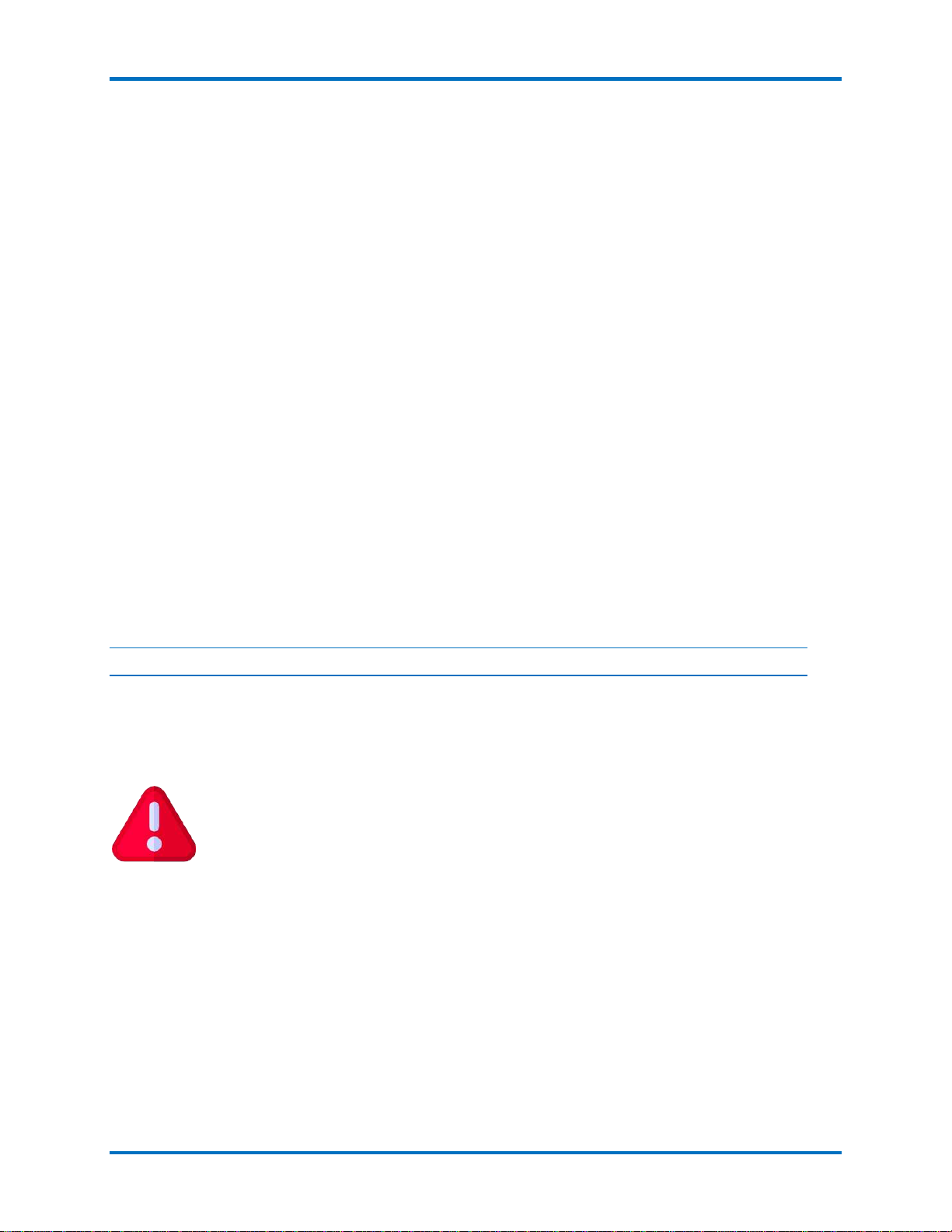
1. Pull the inner rail out of the slide rail until it clicks.
2. Detach the inner rail completely from the slide rail by pulling the white tab forward
They rack may tilt and fall due to incorrect installation or placed on uneven
grounds.
The rack must be placed in a flat surface before you begin to slide the system
barebone in for servicing.
DR365V-HA Setup Guide Initial Installation
© 2023 StoneFly, Inc. | All rights reserved. 12 |P a g e
3. After the inner rail is dislodged, adjust the middle rail back to its original position by pushing the
tab on the middle rail.
DR365V-HA Setup Guide Initial Installation
© 2023 StoneFly, Inc. | All rights reserved. 13 |P a g e
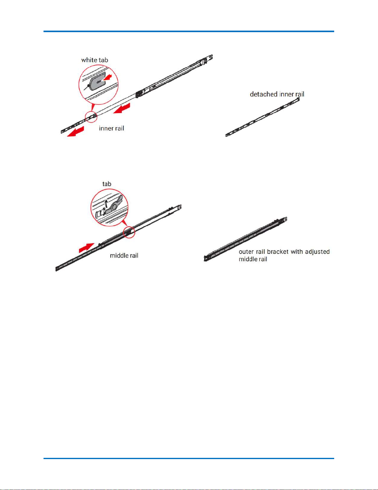
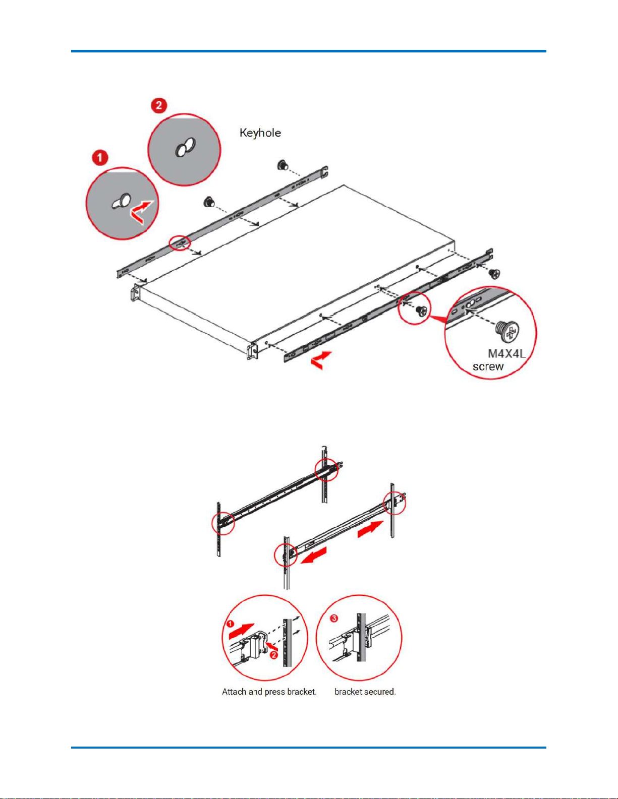
4. Install the inner rail onto the system barebone. Lock the keyholes and secure the screws.
5. Continue installing the outer rail bracket to the mounting frame. Attach the outer rail assembling
to the frame and press the bracket to fix the rail onto the frame. Repeat to fully mount the bracket
assembly.
6. Pull out the middle channel until the ball bearing retainer is locked forward.

DR365V-HA Setup Guide Initial Installation
© 2023 StoneFly, Inc. | All rights reserved. 14 |P a g e
7. Slide the release tab and push barebone into rack. Make sure the barebone is completely installed
onto the rack.
Verify ball bearing retainer is locked forward.
DR365V-HA Setup Guide Initial Installation
© 2023 StoneFly, Inc. | All rights reserved. 15 |P a g e
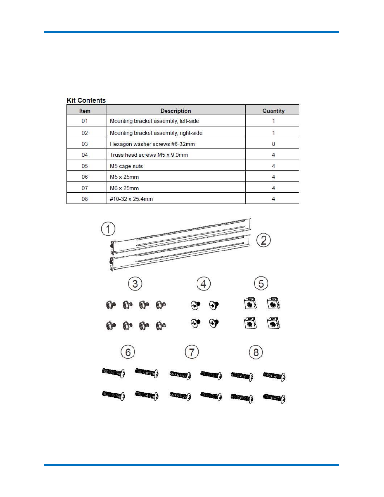
2.1.3 HA RAID Storage Expansion Array / HA Expansion Unit Rack
Installation Instructions
Rack Ear Mount Kit
The following table shows all accessories that came with the rack ear mount kit.

DR365V-HA Setup Guide Initial Installation
© 2023 StoneFly, Inc. | All rights reserved. 16 |P a g e
Installation Procedure
The installation begins with determining the installation position and M5 cage nut (9) insertion locations.
Install the fixed rack ear mount to the rear posts and secure them using truss head screws (4).

DR365V-HA Setup Guide Initial Installation
© 2023 StoneFly, Inc. | All rights reserved. 17 |P a g e
With the assistance of another person holding the enclosure at the installation height, the other person can
place four M5 x 25mm (6) at the front of the enclosure and eight #6-32 screws (3), four on each side, to
secure the enclosure into the rack.

DR365V-HA Setup Guide Initial Installation
© 2023 StoneFly, Inc. | All rights reserved. 18 |P a g e
Slide Rail Kit
The following table shows all accessories that came with the slide rail kit.
The installation begins with determining the installation position (front and rear rack positions) and M5
cage nut (5) insertion location.

DR365V-HA Setup Guide Initial Installation
© 2023 StoneFly, Inc. | All rights reserved. 19 |P a g e
Adjust the length by loosening the four screws on the slide rail. Secure the slide rails to front and rear
posts using truss head screws. Tighten the four screws on the slide to fix the length.
Other manuals for DR365V-HA
1
Table of contents
Other STONEFLY Network Hardware manuals

STONEFLY
STONEFLY DR365-1204 User manual

STONEFLY
STONEFLY ISC-1208s User manual

STONEFLY
STONEFLY DR365V-3605 User manual

STONEFLY
STONEFLY DR365V-2404 User manual

STONEFLY
STONEFLY DR365V-HA User manual

STONEFLY
STONEFLY DR365V-1604 User manual

STONEFLY
STONEFLY DR365V-1205L User manual

STONEFLY
STONEFLY ISC-808S User manual


