Sumake SAF-100 User manual

INSTRUCTION MANUAL
ITEM NO.: SAF-100
SPINDLE TYPE AUTOMATIC SCREW DRIVING MODULE
SAF-100-I-1908A-YM

1
Table of Contents
1. Introduction・・・・・・・・・・・・・・・・・・・・・・・・・・・・・・・・・・・・・・・・・・・・・・・・・・・・・3
2. Item inspection・・・・・・・・・・・・・・・・・・・・・・・・・・・・・・・・・・・・・・・・・・・・・・・・・・3
3. Safety precautions・・・・・・・・・・・・・・・・・・・・・・・・・・・・・・・・・・・・・・・・・・・・・・・・4
4. Specification
(1) Exterior・・・・・・・・・・・・・・・・・・・・・・・・・・・・・・・・・・・・・・・・・・・・・・・・・・・・・・6
(2) Working environment ・・・・・・・・・・・・・・・・・・・・・・・・・・・・・・・・・・・・・・・・・・6
(3) weight ・・・・・・・・・・・・・・・・・・・・・・・・・・・・・・・・・・・・・・・・・・・・・・・・・・・・・・6
(4) Working stroke・・・・・・・・・・・・・・・・・・・・・・・・・・・・・・・・・・・・・・・・・・・・・・・・7
(5) Parts Nomenclature・・・・・・・・・・・・・・・・・・・・・・・・・・・・・・・・・・・・・・・・・・・・・7
5. Installation
(1) Positioning ・・・・・・・・・・・・・・・・・・・・・・・・・・・・・・・・・・・・・・・・・・・・・・・・・・8
(2) Electric screwdriver connection ・・・・・・・・・・・・・・・・・・・・・・・・・・・・・・・・・・9
(3) Signal connector・・・・・・・・・・・・・・・・・・・・・・・・・・・・・・・・・・・・・・・・・・・・・・9
(4) Cylinder connection ・・・・・・・・・・・・・・・・・・・・・・・・・・・・・・・・・・・・・・・・・・・9
6. Pre-job Checking・・・・・・・・・・・・・・・・・・・・・・・・・・・・・・・・・・・・・・・・・・・・・・・・10
7. Test run ・・・・・・・・・・・・・・・・・・・・・・・・・・・・・・・・・・・・・・・・・・・・・・・・・・・・・・10
8. Operating Steps
(1) Equipment ・・・・・・・・・・・・・・・・・・・・・・・・・・・・・・・・・・・・・・・・・・・・・・・・・11
(2) Operation ・・・・・・・・・・・・・・・・・・・・・・・・・・・・・・・・・・・・・・・・・・・・・・・・・・11

2
9. Troubleshooting
(1) Stripping ・・・・・・・・・・・・・・・・・・・・・・・・・・・・・・・・・・・・・・・・・・・・・・・・・・・12
(2) Working fail・・・・・・・・・・・・・・・・・・・・・・・・・・・・・・・・・・・・・・・・・・・・・・・・・・13
(3) Electric screwdriver breakdown ・・・・・・・・・・・・・・・・・・・・・・・・・・・・・・・・・・13
(4) Abnormal vibration ・・・・・・・・・・・・・・・・・・・・・・・・・・・・・・・・・・・・・・・・・・・13
(5) Abnormal vibration ・・・・・・・・・・・・・・・・・・・・・・・・・・・・・・・・・・・・・・・・・・・13
10. Maintenance・・・・・・・・・・・・・・・・・・・・・・・・・・・・・・・・・・・・・・・・・・・・・・・・・・・13

3
1. Introduction
The SAF-100 Automatic Screw Feeder is suitable to automatic production to saves the trouble of
manually picking screws as practiced conventionally. Furthermore, the machine can feed the screw
to screwdriver also screwing to work-piece automatically. The working stability characteristic can
enhance productivity, reduce human cost.
2. Item inspection
Description
Q’TY
Remark
1
SAF-100 module
1set
3
Power supply
1pcs
4
Signal controller
1pcs
5
Instruction manual
1copy

4
3. Safety precautions
Follow instructions depicted in the manual and operate the machine correctly.
<Be sure to follow the instructions>
(1)Warning sign:
【Prohibition Sign】Fire, electric shock, or personnel injury or death may occur if not
observed
【Alarm Sign】Damage of properties, or electric shock or injury of
personal may occur if not observed.

5
(2)Safety rules:
NOT let contaminants such as water or oil enter into machine
Please connect use correct voltage to work.
Follow instructions depicted in the manual and operate the machine correctly
DO NOT dismantle or modify the machine.
If machine smoke, dropped from high place, influent, please remove the power
cord and send the product for repair
NOT place and operate the machine on an unstable table。
DO NOT place machine in a place where flammable or corrosive gas area.
DO NOT put the hand in hopper during working or aim screwdriver to operator.
DO NOT lift the rubber handle to remove machine, avoid the injury if screw loosen
from casing.
Remove the power plug if the machine is to remain idle for a long period of time.
And use specified voltage
Do not place non-spec screws into the hopper.
Do perform regular maintenance of the machine as scheduled.

6
4. Specification
(1) Exterior:
Model No.
Dimension
SAF-100
(2) Working environment :
Model
SAF-100
Voltage
Power supply :AC 220V
Air pressure
5.5(±0.5)kg/cm2=0.54(±0.05)MPa
Temperature
10℃~ 40℃
(3) Weight:
Model
SAF-100
Weight (㎏)
7.2KG

7
(4) working stroke:
SAF-100:
(5) Parts Nomenclature:

8
5. Installation
(1) Positioning:
Positioning hole
Please fix according to the illustration and se screw to integrate SAF-100 with bracket.
Install height
Adjustment steps:
A﹒Push main cylinder to Min.
B﹒Move second cylinder to Max.
C﹒Place one screw to jaw.
D﹒Adjust the install height according to drawing.
E﹒The tip of screw shank needs to be below 0~2mm than surface of work-piece.

9
(2) Electric screwdriver connection:
SAF-100:
(3) Signal connector:
(4) Cylinder connection:

10
6. Pre-job Checking
(1) Install each item correctly.
(2) Confirm that all power connectors, signal joint and air joint are properly installed in place.
(3) Confirm the input power is correct.
(4) Confirm that each sensor and cushion are positioned.
(5) Confirm that all parts are securely locked
(6) Confirm the working air pressure (at 5.5(±0.5)kg/cm2
7. Test run
(1) Confirm that all parts are installed correctly before performing. Especially for voltage and air pressure.
(2) Do not approach the working area during performing to avoid danger.
(3) Turn on the power supply and air pressure source. At this time, the cylinder will move forward
immediately to the upper limit. After reaching the positioning, please check whether the cylinder upper
limit sensor has signal output. If signal output, it is normal.
(4) Make control system to be manual mode, test the cylinder move upward/downward action and feeding
action is normal or not.
1) Main cylinder move downward: Please confirm that the speed and positioning are normal. When
the positioning is normal, the sensor (SR2) signal output.
2) Main Cylinder move upward: Please confirm that the speed and positioning are normal. When the
positioning is normal, the sensor (SR1) signal output.
3) Second cylinder move downward: Please confirm that the speed and positioning are normal. When
the positioning is normal, the sensor (SR4) signal output.
4) Second cylinder move upward: Please confirm that the speed and positioning are normal. When
the positioning is normal, the sensor (SR3) signal output.
(Remark 1: The cylinder working speed adjusted by the speed-control valve.)
(Remark 2:
A. Please adjust sensor positionaim to inductive object if change cushion for stroke.) Make main
cylinder to min.
B. Open casing .

11
C. Loosen fix screw to move sensor. The sensor will be lit once aim to inductive object.
D. Fix screw
(Remark 3: Please refer to 5-3 for sensor signal connector)
5) Feeding: after connecting with screw feeder, please ensure the screw can fed to tip of jaw. And
the screw shank need exceed jaw. Please remove the screw before next feeding.
6) Electric screwdriver : please ensure the electric screwdriver working normal
(5) Please change to AUTO. Mode if manual testing is normal.
8. Operating Steps
(1)Equipment:
(2)Operation
1) Start working after test run.
2) Positioning the work-piece and turn power on. Also check if emergency button release (if install
emergency button). Check if screw feeder is ready.
3) Change to manual mode
4) Check if there is screw inside jaw. If not, please feed one screw first.
5) Start working after checking.
6) Start for automatically working
7) Automatic step: main cylinder downward →second cylinder downward →trigger electric
screwdriver →push screw out to screwing → second cylinder upward →main cylinder upward →
feed next screw →keep working.

12
9. Troubleshooting
(1) Stripping :
1) During replacement, the Work-Piece is not in correct position.
Check if the Work-Piece position is accurate.
2) The torque setting of screwdriver is too big to working.
Please adjust the screwdriver torque setting.(as shown in the figure.)
3) The BIT is bent and cannot be accurately aligned to the screw position.
Check if the BIT is bent.
Change BIT.
4) The BIT is worn after working period of time.
Check if the BIT is worn.
Turn off power of electric screwdriver then replace BIT(as shown in the figure.)
5) The screw head is deformed and abnormal and the BIT can’t align to screw, causing for stripping
issue.
Check if the screws are normal. Change abnormal screws.

13
(2) Working fail:
1) The screwdriver torque setting is too low.
Adjust the torque of the screwdriver to the proper setting(refer to 9-1-2)
2) Workpiece screw hole positioning deviation
Correct the positioning of the work-piece or fixture so that the screw hole is aligned with the
center of the screwdriver.
(3) Electric screwdriver breakdown:
If the Electric Screwdriver cannot rotate, check if the power line is normal.
(4) Abnormal vibration :
Please check the cylinder speed if it is fast. If yes, please adjust the speed control valve .
Please check the buffer cylinder is positioned. If not, please adjust it.
(5) Automatic screw feeder breakdown:
Please refer to the screw feeder manual.
★.If any malfunction than the above, please contact the dealer.
10. Maintenance
Please clean and lubricate the spindle regularly every week.
Check and replace the BIT
※the maintenance time should be shortened if the operation is frequent or the environment is
bad.

EU Declaration of Conformity (DOC)
We: SUMAKE INDUSTRIAL CO., LTD.
4F, No. 351, Yangguang St., Neihu District, Taipei City, Taiwan
declare in sole responsibility that the equipment
Equipment: AUTOMATIC SCREW FEEDER
Model/ Serial No.: SNF-A1, SNF-A2, SNF-A3, SNF-A4, SNF-A8, SNF-A9,
SNF-A10, SNF-A11, SNF-A12, SNF-A13, SF40TH, SF30A,
SF30M, SF30T, SF40A, SF40T, SF501, SF501T, SF502,
SF502T, SAF-100S, SAF-100G, SAF-100L, SAF-100R, SDA,
SF-SERIES
The object of the declaration described above is in conformity with the relevant union
harmonization legislation:
Machinery Directive 2006/42/EC
Low Voltage Directive: 2014/35/EU
RoHS 2011/65/EU
The following harmonised standards and technical specifications have been applied:
EN ISO 12100:2010
EN ISO 13849-1:2023
EN ISO 13850:2015
EN ISO 13857:2019
EN ISO 4414:2010
EN 60204-1:2018
Name and Signature/Position Date and Place
2023/9/26
Mike Su – Managing Director Taipei, Taiwan
SF(SAF)(SDA)(SNF)-D-2310J-YM

NOTE
www.SUMAKE.com
www.AIRCOMPRESSOR.com.tw
Table of contents
Other Sumake Tools manuals

Sumake
Sumake ST-2510A User manual

Sumake
Sumake ST-NH620 User manual

Sumake
Sumake ST-P6634 User manual

Sumake
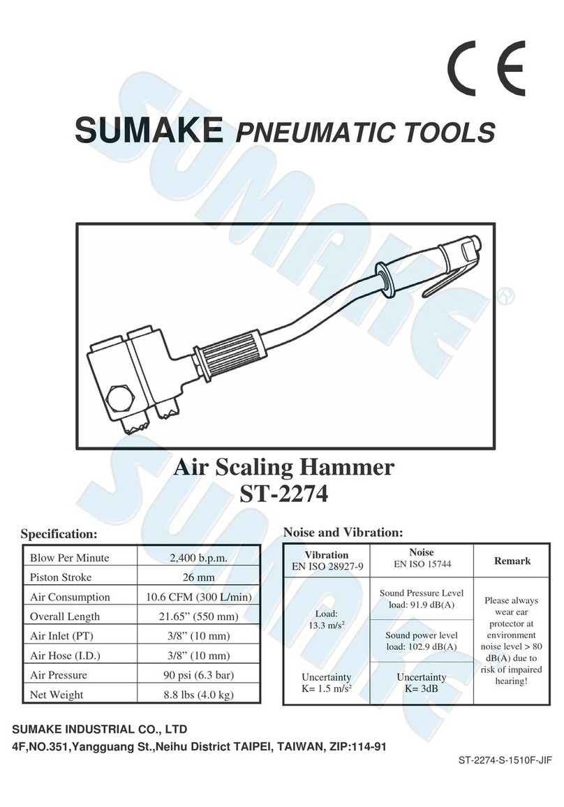
Sumake ST-2274 User manual

Sumake
Sumake SA-4013 User manual
Sumake
Sumake ST-TB100 User manual

Sumake
Sumake SF501 User manual

Sumake
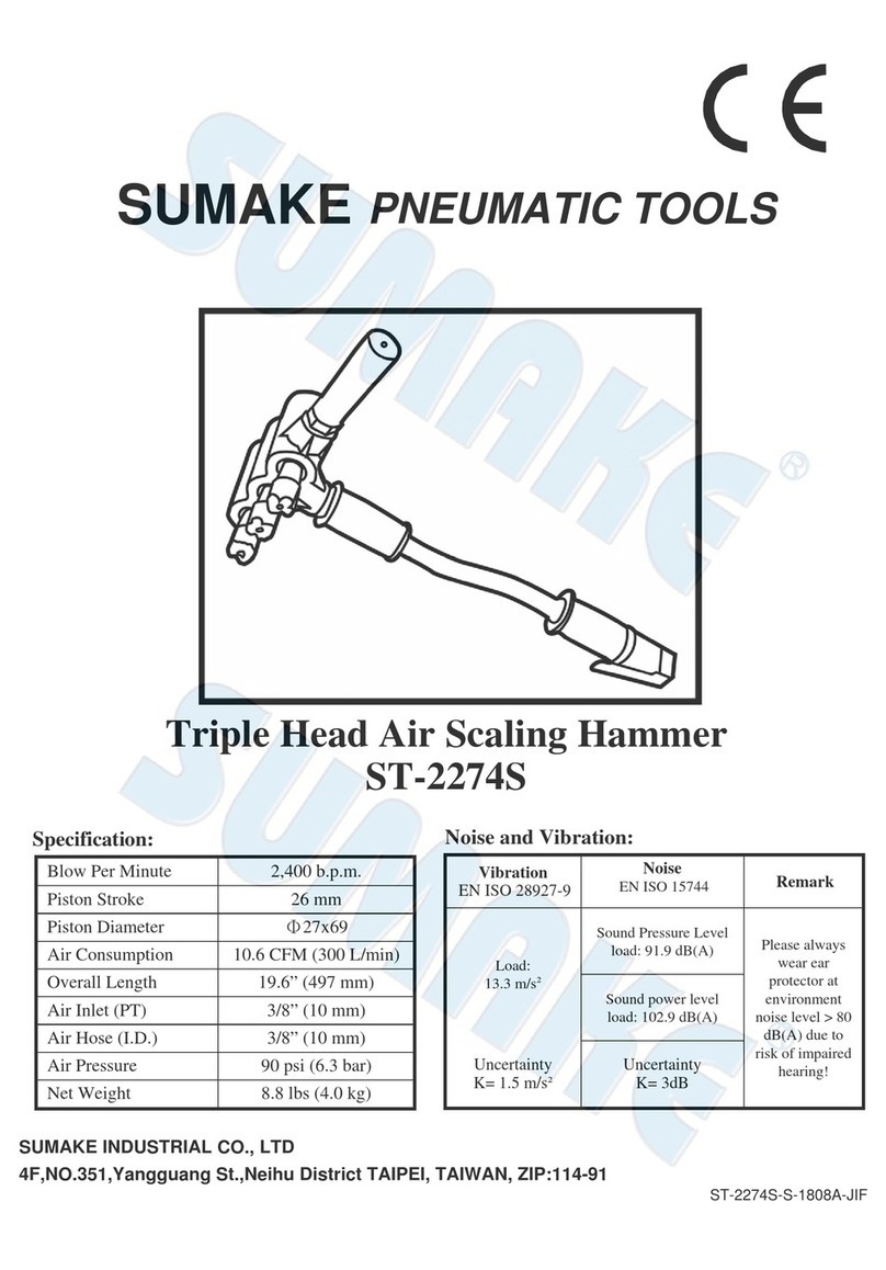
Sumake ST-2274S User manual

Sumake
Sumake SAF-100R User manual

Sumake
Sumake CB-32A User manual
Sumake
Sumake ST-2272 User manual

Sumake
Sumake ST-2272L User manual

Sumake
Sumake ST-6400 User manual

Sumake
Sumake STT-08B User manual

Sumake
Sumake HTT-22 User manual

Sumake
Sumake HR3 Series User manual
Sumake
Sumake ST-2407 User manual

Sumake
Sumake ST-7200 User manual

Sumake
Sumake ST-2560 User manual

Sumake
Sumake HR3 Series User manual