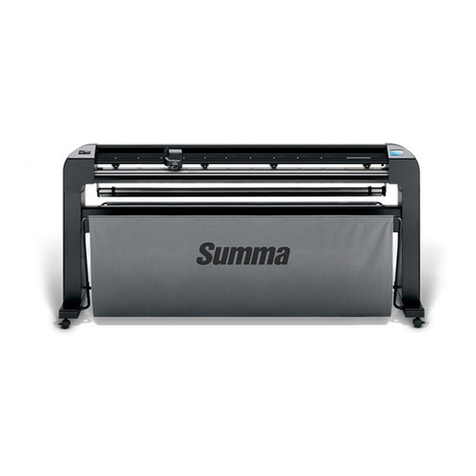
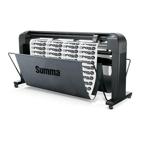
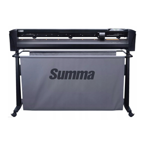
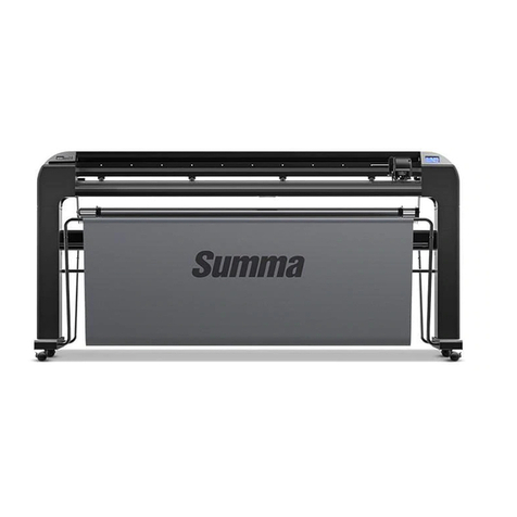
Summa S CLASS User manual

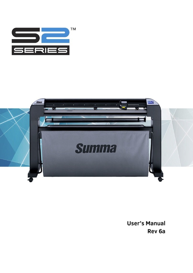
User’s Manual
Rev 007

FCC Notice
The S CLASS™ cutters have been tested and found to comply with the limits for
Class A digital devices, pursuant to Part 15 of the FCC Rules. These limits are
designed to provide reasonable protection against harmful interference when the
equipment is operated in a commercial environment. The cutters generate, use and
can emit radio frequency energy and, if not installed and used in accordance with
the instruction manual, may cause harmful interference to radio communications.
Operation of the cutters in a residential area is likely to cause harmful interference,
in which case the user will be required to correct the interference at his own
expense.
Caution!
Changes or modifications not expressly approved by Summa, which is responsible
for FCC compliance, could void the user’s authority to operate this equipment.
DOC Notice
The S CLASS™ cutters do not exceed the Class A limits for radio noise for digital
apparatus set out in the Radio Interference Regulations of the Canadian
Department of Communications.
Notice
Summa reserves the right to modify the information contained in this User Manual
at any time without prior notice. Unauthorized copying, modification, distribution or
display is prohibited. All rights reserved.
Waste Electrical and Electronic Equipment (WEEE) Directive
Directive 2002/96/EC of the European Parliament and of the Council
The symbol (right) is shown on this product. It indicates that the
product should not be disposed of with regular household waste,
but should be disposed of separately.
Electrical and electronic equipment can contain materials that are
hazardous to the environment and human health and therefore
should be disposed of at a designated waste facility or returned
to your retailer for the appropriate recycling to take place.
If you wish to dispose of this product and the product still functions, please consider
recycling/reusing it by donating it to a charity shop, selling it or part-exchanging it
with your retailer.
Copyright © 2007 Summa bvba

Registering Your Cutter
Please register your cutter on the following link:
http://www.summa.be/registration.html
Failure to register may result in delayed responses to your warranty and service
inquiries.
Contact Information
All inquiries, comments or suggestions concerning this and other Summa manuals
should be directed to:
North America and Asia
Pacific Eastern United States
and Latin America Europe, Africa and
Middle East
Summa, Inc
10001 Lake City Way NE
Seattle, WA 98125
USA
Main Office
+1-206-527-1050
+1-800-527-7778
Fax
+1-206-527-1046
Support
Sales
Web Site
www.summausa.com
Summa East, Inc
222 Jubilee Drive
Peabody, MA 01960
USA
Main Office
+1-978-531-1991
+1-888-527-1050
Fax
+1-978-531-1993
Support
Sales
Web Site
www.summausa.com
Summa, bvba
Rochesterlaan 6
B-8470 GISTEL
Belgium
Main Office
+32 (0)59 270011
Fax
+32 (0)59 270063
Support
Sales
Web Site
www.summa.be

Welcome
Congratulations on your purchase of the new S CLASS™ cutter!
The S CLASS™ cutters are made for sign-makers who demand the very best in cut
quality.
Four versatile modes let you switch between Cutting, Cutting in FlexCut, Plotting or
Pouncing. So even if your workspace is limited, your output options aren't.
Unrivalled tracking delivers guaranteed accuracy on cuts up to 12 meters (40 feet)
long. So you won't have to monitor your cuts, even when you're sending the long jobs
through.
The S CLASS™ T cutters with genuine tangential operation, and not simply
"tangential emulation," handle a wider range of materials and cut with unparalleled
precision.
In short, the S CLASS™ cutters take cutting signs to a new level.
This manual is a reference guide for installing and operating the S CLASS™ cutter
models.

Table of contents I
Table of Contents
1Setup ......................................................................................................1-1
1.1 Unpacking the Cutter.................................................................................. 1-1
1.1.1 Removing the packaging from the cutter................................................ 1-1
1.1.2 Setting up the stand................................................................................ 1-2
1.1.3 Mounting the cutter on the stand............................................................ 1-4
1.2 S CLASS™ Cutter Components................................................................. 1-5
1.2.1 The Cutter as viewed from the front ....................................................... 1-5
1.2.2 The Cutter as viewed from the back....................................................... 1-7
1.3 Connecting the Cutter to the Mains........................................................... 1-9
1.3.1 Grounding (“Earthing”)............................................................................ 1-9
1.3.2 Operating voltage ................................................................................... 1-9
1.3.3 Powering-on the cutter .........................................................................1-10
1.4 Connecting the Cutter to a Computer ..................................................... 1-11
1.4.1 USB connection.................................................................................... 1-11
1.4.1.1 Connecting the S CLASS™ cutter to a PC using a USB cable..... 1-11
1.4.1.2 Connecting the S CLASS™ cutter to a Mac using a USB cable ... 1-12
1.4.2 RS-232 Connection .............................................................................. 1-13
1.5 Loading Media ........................................................................................... 1-14
1.5.1 Pinch roller positioning ......................................................................... 1-14
1.5.2 Pinch roller pressure setting................................................................. 1-15
1.5.2.1 Changing pressure on older models.............................................. 1-15
1.5.2.2 Changing pressure on the other models........................................ 1-16
1.5.3 Loading media...................................................................................... 1-17
1.5.4 Media load procedure........................................................................... 1-20
1.6 Tool Installation......................................................................................... 1-24
1.6.1 Cutters with drag head .........................................................................1-24
1.6.1.1 Knife installation ............................................................................ 1-24
1.6.1.2 Pen installation .............................................................................. 1-28
1.6.1.3 Pouncing pin installation................................................................ 1-28
1.6.2 Cutters with tangential head................................................................. 1-29
1.6.2.1 Tangential knife installation........................................................... 1-29
1.6.2.2 Pen installation .............................................................................. 1-33
1.6.2.3 Pouncing pin installation................................................................ 1-33
1.6.2.4 Drag knife installation.................................................................... 1-34
1.6.3 Replacement of the separation knife blade.......................................... 1-34

S CLASS™ cutter User’s Manual
Table of contents II
2Basic Operation.....................................................................................2-1
2.1 Touch Screen............................................................................................... 2-1
2.1.1 Touch screen.......................................................................................... 2-2
2.1.2 Configuration .......................................................................................... 2-3
2.1.3 Online/Pause.......................................................................................... 2-4
2.1.4 Actions.................................................................................................... 2-4
2.2 How to Set Tool Parameters....................................................................... 2-5
2.2.1 Setting tool type......................................................................................2-5
2.2.2 Changing tool pressure .......................................................................... 2-6
2.2.3 Changing drag knife offset...................................................................... 2-6
2.2.4 Calibrating a tangential knife.................................................................. 2-7
2.3 How to Set Cutting Speed......................................................................... 2-11
2.4 How to Change the User (Quick Parameter Change)............................. 2-13
2.5 How to Make Sure the Sign Has the Correct Size .................................. 2-14
2.6 Touch screen shortcuts............................................................................ 2-16
2.6.1 Changing origin .................................................................................... 2-16
2.6.2 Changing velocity ................................................................................. 2-16
2.6.3 Changing tool pressure ........................................................................ 2-17
2.6.4 Changing user...................................................................................... 2-17
2.7 How to track difficult media...................................................................... 2-18
3OPOS (Optical POSitioning).................................................................3-1
3.1 Introduction.................................................................................................. 3-1
3.2 Basic OPOS operation................................................................................ 3-1
3.2.1 OPOS calibration.................................................................................... 3-2
3.2.2 Media calibration .................................................................................... 3-3
3.3 Detailed OPOS Operation ........................................................................... 3-5
3.3.1 Creating the graphic with the markers.................................................... 3-5
3.3.2 OPOS XY ............................................................................................... 3-8
3.3.3 Printing the graphic................................................................................. 3-9
3.3.4 Loading the graphic into the cutter....................................................... 3-10
3.3.5 Setting the parameters for the OPOS sensor....................................... 3-10
3.3.6 Registering the markers ....................................................................... 3-11
3.3.7 Cutting the contour............................................................................... 3-12
3.4 Automating Tasks with OPOS.................................................................. 3-13
3.4.1 Cutting multiple copies of a graphic on the same roll........................... 3-13
3.4.2 Cutting the same graphic on multiple media sheets............................. 3-14
3.4.3 OPOS Barcode..................................................................................... 3-16
3.5 Cutting through ......................................................................................... 3-17

S CLASS™ cutter User’s Manual
Table of contents III
4Detailed Operation ................................................................................4-1
4.1 Introduction.................................................................................................. 4-1
4.2 Action Menu................................................................................................. 4-1
4.3 Configuration Menu..................................................................................... 4-2
4.3.1 Settings................................................................................................... 4-3
4.3.1.1 Tool.................................................................................................. 4-3
4.3.1.2 Advanced cutting............................................................................. 4-3
Overcut:.................................................................................................. 4-3
OptiCut: ..................................................................................................4-3
FlexCut:..................................................................................................4-4
Panels:.................................................................................................... 4-5
Smoothing: ............................................................................................. 4-5
Concatenation: ....................................................................................... 4-5
4.3.1.3 General............................................................................................ 4-6
Media sensor:......................................................................................... 4-6
Language:............................................................................................... 4-6
Panel Units: ............................................................................................ 4-6
Recut Offset:........................................................................................... 4-6
Cut off margin:........................................................................................ 4-7
Roll up media:......................................................................................... 4-7
Autoload: ................................................................................................ 4-7
Front Margin: .......................................................................................... 4-7
4.3.1.4 OPOS .............................................................................................. 4-8
4.3.1.5 Communication................................................................................ 4-8
Baudrate (RS232):.................................................................................. 4-9
Parity (RS232):....................................................................................... 4-9
RTS/DTR (RS232):................................................................................. 4-9
Emulation language:............................................................................. 4-10
HP-GL origin:........................................................................................ 4-10
DM-PL addressing:............................................................................... 4-10
USB class:............................................................................................ 4-10
4.3.1.6 Speed in detail............................................................................... 4-11
Velocity long vectors:............................................................................ 4-11
TurboCut:.............................................................................................. 4-11
4.3.2 Tests and setup.................................................................................... 4-12
4.3.2.1 OPOS settings............................................................................... 4-12
4.3.2.2 Length calibration .......................................................................... 4-12
4.3.2.3 Coil setup....................................................................................... 4-12
4.3.2.4 Calibrate knife................................................................................ 4-12
4.3.2.5 Factory defaults............................................................................. 4-13
4.3.2.6 Confidence test.............................................................................. 4-13
4.3.2.7 Media sensor setup ....................................................................... 4-13
4.3.2.8 DIN A4 Test................................................................................... 4-14
4.3.2.9 RS232 test..................................................................................... 4-14
4.3.2.10 Calibrate touch screen................................................................... 4-14
4.3.2.11 ROM REVISION............................................................................ 4-14
4.3.2.12 Copy current user.......................................................................... 4-14
4.3.3 User...................................................................................................... 4-15

S CLASS™ cutter User’s Manual
Table of contents IV
5Maintenance and Cleaning...................................................................5-1
5.1 Introduction.................................................................................................. 5-1
5.1.1 Cleaning the drive system...................................................................... 5-1
5.1.2 Cleaning the media sensors................................................................... 5-2
5.1.3 Cleaning the Y-Guide Rail...................................................................... 5-3
5.1.4 Cleaning the nose piece (tangential machine only)................................ 5-3
5.1.5 Cleaning the OPOS system.................................................................... 5-4
5.1.6 Changing the fuse .................................................................................. 5-5
6Specs and Genaral Information ...........................................................6-1
6.1 Introduction.................................................................................................. 6-1
6.1.1 Product features ..................................................................................... 6-1
6.2 Specifications.............................................................................................. 6-3
6.2.1 Cutter...................................................................................................... 6-3
6.2.2 Media...................................................................................................... 6-3
6.2.3 Knife, pen and pouncing tool.................................................................. 6-4
6.2.4 Interface.................................................................................................. 6-5
6.2.5 Firmware................................................................................................. 6-5
6.2.6 Performance........................................................................................... 6-6
6.2.7 Certifications........................................................................................... 6-6
6.2.8 Environmental......................................................................................... 6-7
6.2.9 Electrical................................................................................................. 6-7

S CLASS™ cutter User’s Manual
Table of contents V
List of Figures
1-1 S CLASS™ cutter fully boxed..............................................................................1-1
1-2 Contents OF box stand........................................................................................1-2
1-3 Mounting horizontal panel....................................................................................1-2
1-4 Mounting feet and casters....................................................................................1-2
1-5 Mounting basket tubes.........................................................................................1-3
1-6 Preparing to install the linen basket.....................................................................1-3
1-7 Orientation of the holes in the c-shaped tubes ....................................................1-3
1-8 Stand fOR the S CLASS™ cutter completely assembled....................................1-4
1-9 Position of the screws..........................................................................................1-4
1-10 S CLASS™ cutter, front view.............................................................................1-5
1-11 S CLASS™ cutter, rear view..............................................................................1-7
1-12 Properly grounded connection...........................................................................1-9
1-13 Cutter is loaded and ready...............................................................................1-10
1-14 Cutter is ready no media loaded......................................................................1-10
1-15 POsition pinch rollers.......................................................................................1-14
1-16 Standard pressure ...........................................................................................1-15
1-17 Reduced pressure............................................................................................1-15
1-18 reducing pressure............................................................................................1-16
1-18 Pinch roller lever..............................................................................................1-17
1-19 Media flanges...................................................................................................1-17
1-20 Position media flange on cutter........................................................................1-17
1-21 Feeding roll media without using media flanges..............................................1-18
1-24 Removing the drag knife holder from the clamp..............................................1-24
1-25 Removing the knife from the standard drag knife holder.................................1-24
1-27 Dual clamp drag head......................................................................................1-25
1-28 Knife pressure test pattern...............................................................................1-26
1-29 Removing the tangential knife holder...............................................................1-29
1-30 Removing knife from the tangential knife holder..............................................1-29
1-32 Inserting the tangential knife holder.................................................................1-30
1-33 Knife depth adjustment....................................................................................1-30
1-34 Knife pressure test pattern...............................................................................1-31
1-35 Razor blade for automatic SEPARATION OF MEDIA.....................................1-34
2-1 Touch screen.......................................................................................................2-1
2-2 screen saver ........................................................................................................2-1
2-3 Online status screen............................................................................................2-4
2-4 Correct knife offset pattern...................................................................................2-7
2-5 Possible knife calibrations....................................................................................2-8
2-7 Length calibration pattern ..................................................................................2-14
2-8 Shortcut areas in start-up screen.......................................................................2-16
3-1 Position media fro multiple sheet.......................................................................3-15
3-2 Opos barcode job loaded...................................................................................3-16
3-3 FlexCut principle................................................................................................3-17
combined contour cut and cutting through...............................................................3-20
4-1 Action Menu.........................................................................................................4-1
4-2 Configuration Menu..............................................................................................4-2
4-3 Overcut ................................................................................................................4-3
4-4 S Sensor setup ..................................................................................................4-13
5-1 Lifting the pinch roller...........................................................................................5-2
5-2 Placement of vinyl strip........................................................................................5-2
5-3 Media sensors S CLASS™ cutters......................................................................5-2
5-4 Sliding surfaces on Y-guide rail ...........................................................................5-3
5-5 Cleaning OPOS sensor........................................................................................5-4
S CLASS™ cutter User’s Manual
Table of contents VI
5-6 Power entry module.............................................................................................5-5

S CLASS™ cutter User’s Manual
Table of contents VII
List of Tables
1-1 Default RS-232 settings of the S CLASS™ cutter.............................................1-13
6-1 S CLASS™ Cutter specifications.........................................................................6-3
6-2 S CLASS™ media specifications.........................................................................6-3
6-3 S CLASS™ tools..................................................................................................6-4
6-4 S CLASS™ interface specifications.....................................................................6-5
6-5 S CLASS™ firmware ...........................................................................................6-5
6-6 S CLASS™ performances...................................................................................6-6
6-7 S CLASS™ environmental specifications............................................................6-7
6-8 S CLASS™ accessories....................................................................................6-10

Setup 1-1
1 Setup
1.1 Unpacking the Cutter
NOTE: Save the shipping box and any other packaging items in case the cutter needs
to be shipped. Do not ship the cutter without first completely repacking it in its original
packaging.
Before unpacking the cutter, make sure that there is enough space to assemble the
stand and to set the cutter aside to insert the stand screws.
CAUTION: For safety reasons, no fewer than two people should be involved in
unpacking the cutter.
1.1.1 Removing the packaging from the cutter
1. Remove the straps and the staples and open the lid of the box.
2. The cutter is packed in foil and sits in front of the box. Behind the cutter is the box
containing the stand. The accessories are located at the bottom in a separate box.
Check first whether everything is present.
3. Do not throw away the packaging. Shipping it without the original box voids any
warranty.
FIG 1-1
1-1 S CLASS™ CUTTER FULLY BOXED

S CLASS™ cutter User’s Manual
Setup 1-2
1.1.2 Setting up the stand
1. Verify that the stand is complete. The box containing the stand should contain
following:
a. 2 legs, left and right
b. 2 feet, left and right
c. Horizontal panel
d. Media flanges
e. Total of 7 tubes for [media] basket
f. Linen media basket
g. Bag of 4 casters, screws and other accessories to mount the stand
FIG 1-2
1-2 CONTENTS OF BOX STAND
2. Mount the horizontal panel between the two legs of the stand with 4 screws at
each side.
FIG 1-3
1-3 MOUNTING HORIZONTAL PANEL
3. Turn the stand upside down and mount the 2 feet at each side with 4 screws. Take
care to position the feet so that all the holes in the feet corresponds to the holes in
the legs (left and right) as in the picture (1), and the 4 holes in the feet all point
towards the middle (2). Screw in the 4 casters.
FIG 1-4
1-4 MOUNTING FEET AND CASTERS

S CLASS™ cutter User’s Manual
Setup 1-3
4. Attach on the left and right the 4 tubes for the basket as shown in figure 1-5 below.
On each tube, put the end cap (1) and the two saddle clips (2) to fix the tube in its
place. Position the shorter tube (3) at the rear side (side of the horizontal panel).
FIG 1-5
1-5 MOUNTING BASKET TUBES
5. Turn the stand upright and put the media basket on the horizontal panel as shown
in figure 1-6 below.
FIG 1-6
1-6 PREPARING TO INSTALL THE LINEN BASKET
6. Take one of the large c-shaped tubes and put it through the front hem in the linen
basket. Make sure the holes are oriented right-side up so that the tubes click
securely in place. Then put the tube on the two front tubes that stick out of the
feet. Slide the tubes together, while pressing down on the spring loaded ball
stopper, until the ball locks into place.
FIG 1-7
1-7 ORIENTATION OF THE HOLES IN THE C-SHAPED TUBES
7. Click a saddle clip onto one side of the tube. Insert the other end of the tube
through the middle hem of the linen basket and then into the hole in the leg of the
stand. Then guide the other end of the tube into the hole on the leg and secure
with a saddle clip.

S CLASS™ cutter User’s Manual
Setup 1-4
8. Make sure the linen basket is guided under the horizontal panel. Take the last
large c-shaped tube and feed it through the rear hem in the linen basket. Then put
the tube on the two rear tubes that stick out of the feet. Make sure the holes are
oriented right-side up so that the tube clicks securely on the tubes. The finished
stand should look like the stand in the picture below (Figure 1-8).
FIG 1-8
1-8 STAND FOR THE S CLASS™ CUTTER COMPLETELY ASSEMBLED
9. The right leg has a hole in the foot and a cutout in the leg to guide the power cable
and data cable. If you plan to use these cable guides, then put the cables in place
before mounting the cutter on the stand.
1.1.3 Mounting the cutter on the stand
1. Carefully take the cutter out of the box and lay it on its back (first spread out the
cardboard of the stand box, and then rest the cutter on that cardboard). Then
insert left and right two screws and turn them 3 turns in. Do not put a screw in at
the front.
FIG 1-9
1-9 POSITION OF THE SCREWS
2. Put the cutter on its stand. Put in the two extra screws in . Then secure all six
screws.
3. Loosen the cutting head. Raise the pinch rollers to remove the protection strip
from underneath the pinch roller assemblies.

S CLASS™ cutter User’s Manual
Setup 1-5
1.2 S CLASS™ Cutter Components
1.2.1 The Cutter as viewed from the front
FIG 1-10
1-10 S CLASS™ CUTTER, FRONT VIEW
1. Pinch rollers: The pinch rollers clamp the media to the drive system to ensure
accurate tracking. The S120(T) has one and the S160(T) and S 140(T) have two
extra pinch rollers to ensure that wide media stays flat in the middle. The outer
drive pinch rollers have a selectable pressure; the extra rollers in the middle can
be enabled or disabled.
2. Touch panel: All cutter activity can be initiated from the 320x240 dot touch panel.
The panel displays information about the cutter’s current status and/or actions that
need to be taken.
3. Pinch roller lever: This lever is used to raise and lower the pinch rollers for media
loading.
4. Media drive sleeves: The media drive sleeves move the media only when the
pinch rollers are in the “down” position. The following table lists the number of
sleeves installed on each model of the S CLASS™ cutters.
Number of sleeves S75 (T) S120 (T) S140 (T) S160 (T)
Short sleeve 4 7 8 9
Long sleeve 1 1 1 1

S CLASS™ cutter User’s Manual
Setup 1-6
5. Tool carriage: The tool carriage is the mount for the knife holder, pen or pouncing
tool. It has also holds the Optical POSitioning sensor (OPOS) and a cut-off knife to
cut a sheet from the roll when a job is finished.
6. Cutting strip: A self-healing orange strip helps avoid any damage to the knife tip
when no media has been loaded. Since cutting is done on the cutting strip, it is
essential that the strip remains intact.
7. Pouncing strip: An extra black strip to pounce on.
8. Tool holder: The left end cap has a rim so it can be used for tool storage.
9. Screws to secure the cutter base: Make sure all three screws are secured at
each side before the cutter is used.
10. Media basket: The stand and linen media basket come standard with all S
CLASS™ cutters.

S CLASS™ cutter User’s Manual
Setup 1-7
1.2.2 The Cutter as viewed from the back
FIG 1-11
1-11 S CLASS™ CUTTER, REAR VIEW
1. Pinch rollers: The pinch rollers clamp the media to the drive system to ensure
accurate tracking. The S120(T) has one and the SS160(T) and S 140(T) have two
extra pinch rollers to ensure that wide media stays flat in the middle. The outer
drive pinch rollers have a selectable pressure; the extra rollers in the middle can
be enabled or disabled. Do not move the pinch roller assemblies while holding
them from this side only.
2. Pinch roller lever: This lever is used to raise and lower the pinch rollers for media
loading.
3. The fuse box: The fuse is located at the right side of the power entry module.
Check the specification section to see which fuse is used in the S CLASS™ cutter.
CAUTION: For continued protection against risk of fire, replace only with the same type
and rating of fuse.
4. Power On/Off switch: This rocker switch, in the middle of the power entry
module, sets the cutter’s power to ON or OFF. To switch on the power, press the
“I” side of the rocker switch. To switch off the power, press the “O” side of the
rocker switch.

S CLASS™ cutter User’s Manual
Setup 1-8
5. AC power cord receptacle: It is located at the left-hand side of the power entry
module. The power-up procedure is explained in detail in Section 1.3. Always use
a power cord that was delivered with your cutter.
6. USB port: This interface is based on the standards specified in Universal Serial
Bus Specifications Revision 1.1. It allows a high-speed bi-directional
communication between the host computer and the cutter.
7. RS-232 port: This DB-9P connector provides serial bi-directional communication
between the cutter and a host computer.
8. Screws to secure the cutter base: Screws (3 left and 3 right) hold the cutter
base to its stand. All the screws must be properly tightened before using the
cutter.
9. Tubes for media basket: Tubes in the back and front hold the media basket.
They can easily pulled outwards to put the basket in its place.
10. Casters: The casters on the stand are equipped with locking brakes. Once the
cutter has been moved to its new location, press the brakes with your foot to lock
the casters.
11. Media basket: The stand and linen media basket come as standard equipment
with all S CLASS™ cutters.
12. Roll media guide bushes: The two flange guides serve to keep the media roll in
place when media is pulled from the roll.
13. Media support rollers: Rotating support rollers for the media roll.

S CLASS™ cutter User’s Manual
Setup 1-9
1.3 Connecting the Cutter to the Mains
1.3.1 Grounding (“Earthing”)
CAUTION: An insulated ground conductor must be installed as part of the branch
circuit that supplies power to the wall outlet to which the cutter is connected. The
ground conductor must have the same size, insulation material and thickness as the
grounded and ungrounded branch circuit supply conductors, but the insulating seat
should be green or green with yellow striping.
The ground conductor described above must be grounded at the electrical distribution
board or, if power is supplied by a separate system, at the power supply
transformer/motor generator set.
The wall sockets into which the cutter is plugged must be of the grounded type. The
grounded conductors serving the wall socket must be properly connected to the
ground.
For emergency access, the cutter should be installed near the socket-outlet for easy
access.
MAKE SURE THIS
IS CONNECTED TO A
MAKE SURE THIS IS
CONNECTED TO A
THREE-PIN
PLUG
EUROPE:
USA
OUTLET
:
THREE-PIN
KNOWN GROUND
KNOWN EARTH
FIG 1-12
1-12 PROPERLY GROUNDED CONNECTION
1.3.2 Operating voltage
CAUTION: Before changing the fuse, make sure that the cutter is completely
disconnected from its power source.
CAUTION: For continued protection against risk of fire, replace only with the same type
and rating of fuse.
Fuse Rate: T2.0A, 250V SCHURTER SPT OR EQUIVALENT.
The power supply detects the line voltage and switches automatically between 110V
and 230V.
Other manuals for S CLASS
2
Table of contents
Other Summa Cutter manuals

Summa
Summa SummaSign Pro SL D-series User manual

Summa
Summa S Class 2 OPOS-CAM User manual

Summa
Summa SummaCut D160SE User manual

Summa
Summa S Class 2 OPOS-CAM User manual

Summa
Summa L3214 User manual

Summa
Summa SUMMACUT User manual

Summa
Summa S Class 2 OPOS-CAM User manual

Summa
Summa S3 Series User manual

Summa
Summa L1810 User manual

Summa
Summa S2 SERIES User manual

Summa
Summa SummaSign D500 User manual

Summa
Summa SummaCut D120 User manual

Summa
Summa S CLASS User manual

Summa
Summa S One Series User manual

Summa
Summa SummaCut D120 User manual

Summa
Summa L1810 User manual

Summa
Summa S 75 User manual

Summa
Summa L1810 User manual

Summa
Summa L1810 2nd generation User manual