manuals.online logo
Brands
  1. Home
  2. •
  3. Brands
  4. •
  5. Sunjoy
  6. •
  7. Outdoor Furnishing
  8. •
  9. Sunjoy L-GZ340PST-3A User manual

Sunjoy L-GZ340PST-3A User manual

DO NOT RETURN TO
RETAILER
IF YOU HAVE ANY QUESTIONS OR CONCERNS
PLEASE VISIT OUR WEBSITE AT:
www.sunjoyonline.com
OR TOLL FREE AT:
Production Number:20193442
1-866-578-6569
SUNJOY GROUP INTERNATI ONAL
PTE LTD
619 Slack
St reet
Steubenville, Ohio 43952 USA
ASSEMBLY INSTRUCTIONS
ITEM# L-GZ340PST-3A
SKU# 108718
THIS UNIT IS HEAVY!
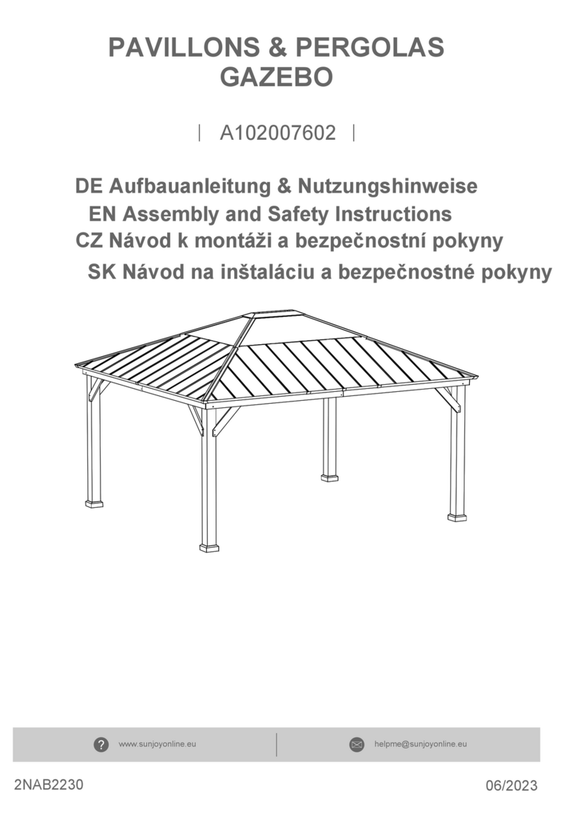
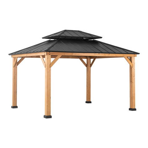
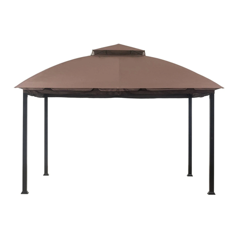
CHATHAM HARDTOP GAZEBO 10’x12’
WARNING:
In order to reduce the risk of personal injury and damage to equipment, basic safety precautions should always
be followed when assembling and using this product. Read all instructions carefully before assembly and use.
All you will need is a screwdriver, a hammer and two ladders.
NOTE: DO NOT ASSEMBLE THIS ITEM ALONE FOR SAFETY.
IMPORTANT:
1. Keep all children and pets away from assembly area. Children and pets should be supervised when they are
in the area of gazebo construction.
2. The area for assembly should not be less than 6 feet from any obstruction such as fence, garage, house,
overhanging branches, laundry line or electrical wires.
3. This unit is heavy. Do not assemble this item alone. Six people are recommended for safe assembly.
4. Some parts may contain sharp edges. Wear protective gloves if necessary during assembly.
5. When assembling and using this product, basic safety precautions should always be followed to reduce the
risk of personal injury and damage to equipment. Please read all instructions before assembly and use.
6. For outdoor use only. Install on level ground. Stakes are provided to secure the gazebo in grass ground. If you
wish to secure the gazebo to a wood deck or concrete surface, you will need to purchase fasteners appropriate
for these surfaces. These are readily available at your local hardware store or home center.
7. Check all bolts for tightness before and during usage.
8. Please check your state and local regulations prior to purchasing. Some jurisdictions may require permits for,
or otherwise regulate, installation and use.
9. In areas subject to frequent severe weather, securing the gazebo to a deck, concrete patio or footings is
recommended.
10. Removal of accumulated snow on the gazebo roof with a roof rake is recommended. In areas that are
regularly subject to blizzard conditions however, removal of the roof panel is suggested. The assembled roof
structure can simply be left in tact until warmer conditions return.
Description Big
Top Frame A1 2
Big Top Bar B1 2
Small Top Support Beam C1 4
Small top connector D1 1
Hook E1 1
Top Roof Small Panel F1 2
Top Roof Long Panel G1 2
Small Top Cover 4
Small Top Roof Cover I1 1
Post B2 4
Base cover D2 4
Base E2 4
Slanting Bar Connector N24
Middle beam
connector G2 4
Lower Beam
Connector H2 4
Short beam O24
Long beam P24
Arc Support Q28
Long Pipe 1 R2a 2
Long Pipe 2 R2b 2
Parts List
CS NO
P10161A01131
P10162A01131
P10227A01131
P10183B01131
P12601C01131
P11971C05131
P11972C05131
P12087A01131
P12086A01131
P11114C05131
P11527A06131
P11630A01131
P10718A01131
P10817A01131
P10818A01131
P11078D01131
P11079D01131
P11833B05131
P12136A01131
P12137A01131
Part
NO QTY Image
H1
Short Pipe 1S2a 2
Short Pipe 2 S2b 2
Top Slanting Bar P3 4
Top Beam B3 4
Long side left roof panel 1 C3 2
Long side right roof panel 1 D3 2
Long side left roof panel 2 E3 2
Long side right roof panel 2 F3 2
Long side left roof panel 3 G3 2
Long side right roof panel 3 H3 2
Short side roof panel 1 I3 2
Short side left roof panel 2 J3 2
Short side right roof panel 2 K3 2
Short side left roof panel 3 L3 2
Short side right roof panel 3 M3 2
4
4
Big roof panel cover (corner) N3
Big roof panel cover (middle) O3
4
Big Roof Top Beam
(Short Side) (3)
R34
Big Roof Top Beam
(Short Side) (5)
S3 4
4
P12138A01131
P12139A01131
P10364B05131
P10445A01131
P11982C05131
P11983C05131
P11980C05131
P11981C05131
P11978C05131
P11979C05131
P11977C05131
P11975C05131
P11976C05131
P11973C05131
P11974C05131
P12088A01131
P12089A01131
P13095B01131
P13096B01131
P13097B01131
P13098B01131
P13099B01131
P13001C01131
4
4
Big Roof Top Beam
(Short Side) (1) Q3
Big Roof Top Beam
(Long Side) (1)
Big Roof Top Beam
(Long Side) (3)
Big Roof Top Beam
(Long Side) (5)
T3
U3
V3
AA Bolt M6*20 48 PCS
BB Flat Washer M6(Large)112 PCS
DD Nut M6 16 PCS
FF Bolt M6*65 16 PCS
GG Bolt M6*45 32 PCS
HH Spring Washer M6 56 PCS
ZWrench M6 2PCS
Hardware Pack 1
Mosquito netting R 1
Vented roof netting T1 1
16
P00324B01902
P00325B01902
P92001A01001
H02020C11
H19001C11
H14001C11
H02065C11
H02045C11
H13001C11
H00001C12
Magnet T2
B2
Step 1
Fig.3
Fig.1
Fig.2 Fig.5
Fig.4
B2
B2 B2
D2
D2
D2
D2
Q2
Q2
Q2
Q2
Q2
O2
O2
O2
O2
P2P2
P2
P2
N2
N2
N2
N2G2
G2
G2
G2
H2
H2
H2
H2
Fig.2: Attach Slanting bar connector (N2) to Post (B2) by using bolt (AA) and washer (BB).
Fig.3: Attach Middle beam connector (G2, H2) to Long beam (P2)/short beam(O2) by using bolt (FF), washer
(BB) and nut (DD).
Fig.4: Attach Long beam (P2)/short beam(O2) to Post (B2) by using bolt (AA), washer (BB) and spring washer
(HH).
Fig.5: Attach Support piece (Q2) to Post (B2) and Beam O2 (P2) by using bolt (GG), washer (BB) and spring
washer (HH).
Fig. 1: Fit Base cover (D2) to Post ( B2), attach Post base (E2) to Post (B2) by using bolt (AA) and washer (BB).
Fig.1
AA
BB
AA BB
Fig.3
E2
B2
D2
Fig.2
BB
AA AA
BB
B2
N2
BB
FF
DD
BB
O2(P2) O2(P2)
G2
H2
Fig.4
O2(P2)
AA
B2
N2Fig.5
O2(P2)
B2
N2
Q2
GG
BB
HH
AA Bolt M6*20 112 PCS
BB Flat Washer M6(Large)146 PCS
CC Bolt M6*55 12 PCS
EE Bolt M6*358 PCS
ZWrench M6 2PCS
Hardware Pack 2
H02020C11
H19001C11
H02055C11
H02035C11
H00001C12
DD Nut M6 12 PCS
H14001C11
GG Bolt M6*45 2 PCS
H02045C11
BB
HH GG
BB HH
Fi
g.6 Connect Short big top frame bar (A1) and Long big top frame bar (B1) by using bolt (AA) and
washer (
BB).
Fig
.7-1 Attach Big top slanting bar (P3) to Short big top frame bar (A1) and Long big top
frame bar (B1) by
using bolt (AA) and washer (BB).
Fig
.7-2: Attach Big top slanting bar (P3) to Slanting bar connector (N2) by using bolt (AA) and washer (BB).
Step 2
Fig.6
Fig.8-2
Fig.8-1
Fig.9-11
Fig.12
Fig.13
Fig.14
A1 B1
B2
B2 B2
B2
D2 D2
D2
D2
Q2
S3
Q2Fig.7-2
Q2 Q2
S3O2
O2P2
P2
P3
B3 B3
P3
P3
R2b
S2b
S2a
Q3
R3Q3
R3
V3
U3U3
T3
Fig.7-1
T3
V3
Fig.6
B1
B1
A1
A1
AA AA
AA
AA BB
BB
BB
BB
Fig.7-1
A1 B1
P3
AA
BB
AA
BB
Fig.7-2 P3
B2
N2
AA
BB Fig.8-1Fig.8-2
AA
BB
B1
B3
B3
BB
BB
DD
CC
Fig
.8-1 Attach Big top middle beam (B3) to Long big top
frame bar (B1) by using bolt (AA) and washer (BB).
Fig
.8-2: Attach Big top middle beam (B3) to Middle beam connector (G2) by using bolt (CC), washer (BB)
and nut (DD).
G2
Fig.15
Fig.16
Fig.17
Fig.18
R2a
Fig.11
Fig.9
Fig.10
B1
D1
B1
A1
C1
C1 C1 A1
Fig.9Fig.11
Fig.10
D1
E1
E1
D1
C1
A1
C1
AA
BB
BB
BB
DD
CC
Fig.10: Screw the Hook (E1) to Small top connector (D1).
Fig.9: Connect Small top slanting bar (C1) and Small top connector (D1) by using bolt (CC), washer (BB)
and nut (DD).tighten all the bolts by wrench.
Fig.11: Attach Small top slanting bar (C1) to Short big top frame bar (A1) by using bolt (AA) and washer (BB).
Fig.12
AA
BB
AA
BB
F1 G1
G1
F1 F1 G1
Fig.13 Fig.14
H1 I1
H1
H1
H1 H1 H1
EE
BB BB
EE GG
BB
Fig.12: Attach Small top roof panel 1 (F1) and Small
top roof panel 2 (G1) to Small top slanting bar (C1) by
using bolt (AA) and washer (BB).
Fig
.13: Attach Small top roof panel cover (H1) to Small top slanting bar (C1) by using bolt (EE) and washer (BB).
Fig
.14 Attach Small top roof cover (I1) to Small top connector (D1) by using bolt (GG) and washer (BB).
Fig.15Fig.16
Fig.17Fig.18
P3
B3
B3
P3
P3
P3
B3
B3
AA
BB
BB
BB
BB
BB
BB
BB
BB
AA
AA
Q3/R3/T3/U3
AA
AA
AA
AA
AA
S3/V3
R2a/S2a R2b/S2b
Fig
.15: Connect Big top beam (Q3) to Big top slanting bar (P3) and Big top middle beam (B3) by using bolt (AA)
and washer (BB). (Use the same way to assemble R3/T3/U3 respectively.)
Fig .16:Connect Big top beam (S3) to Big top slanting bar (P3) and Big top middle beam (B3) by using bolt (AA) and
washer (BB). (Use the same way to assemble V3 respectively.)
Fig
.17 Attach Long netting bar R2a to Big top slanting bar (P3) and Big top middle beam (B3) by usi
ng bolt (AA)
and washer (BB). (Use the same way to assemble S2a respectively.)
Fig
.18: Attach Long netting bar R2b to Big top slanting bar (P3) and Big top middle beam (B3) by usi ng bolt
(AA) and washer (BB). (Use the same way to assemble S2b respectively.)
AA Bolt M6*20 44 PCS
BB Flat Washer M6 (Large)60 PCS
EE Bolt M6*35 16 PCS
Hardware Pack 3
H02020C11
H19001C11
H02035C11
Step 3
Fig. 19 Fig. 20
Fig. 21-1
Fig. 21-2
Fig. 22 E3
D3
C3
F3
G3
I3
H3
J3 K3
L3
M3
N3 O3 O3
N3 N3
Fig. 19 Fig. 20-1
I3
P3
BB
P3
B3
K3
B3
P3
P3
P3
P3
AA
AA
AA
BB
BB
BB BB
Fig. 19: Attach downer roof panel to upper roof panel in this way .
Fig. 20-1: Attach Short side left roof panel (I3) to Big top slanting bar (P3) by using bolt (AA) and washer (BB).
Fig. 20-2
I3
AA AA
J3
Fig. 20-2: Attach Short side left roof panel (J3/K3) to Big top slanting bar (P3) and Big top middle beam (B3)
by using bolt (AA) and washer (BB).
Fig. 20-3
I3
K3
J3
L3M3
BB
AA
Fig. 20-3: Attach Short side left roof panel (L3/M3) to Big top slanting bar (P3) and Big top middle beam (B3)
by using bolt (AA) and washer (BB).
Fig.21-1: Insert one end of Big roof panel cover(N3) into the hole of Small top slanting bar (C1).
Fig.21-2: Attach another end of Big roof panel cover (N3) to Big top slanting bar (P3) by using bolt (EE) and washer
(BB).
Fig. 20-4: Attach Long side left roof panel (C3/D3) to Big top slanting bar (P3) and Big top middle beam (B3)
by using bolt (AA) and washer (BB).
I3
J3K3
L3M3
C3D3
P3
P3
B3
AA AA
BB
BB
Fig. 20-4
I3
J3K3
L3M3
C3D3
P3P3
B3
AA
BB
E3F3
Fig. 20-5
I3
J3K3
L3M3
C3D3
E3F3
G3H3
Fig. 20-6
AA
BB
AA
BB
AA
BB
Fig. 20-5: Attach Long side left roof panel (E3/F3) to Big top slanting bar (P3) and Big top middle beam (B3)
by using bolt (AA) and washer (BB).
Fig. 20-6: Attach Long side left roof panel (G3/H3) to Big top slanting bar (P3) and Big top middle beam (B3)
by using bolt (AA) and washer (BB).
Fig. 21-1
N3
C1
Fig. 21-2
N3N3N3
BB
EE
BB
EE
BB
EE
O3
O3
BB
EE
BB
EE
Fig. 22
Fig.22: Attach another end of Big roof panel cover (O3) to Big top middle beam (B3) by using bolt (EE) and washer
(BB).
II Stake ¢8*180 8PCS
JJ Plastic ring 52 PCS
Hardware Pack 4
P12401A01001
P90701A07001
Step 3
Fig. 23
Fig. 24
Fig. 25
Fig. 26
Fig. 27
Made in China
Fig.17: Place the Magnet (T2) into the pockets of the vented roof netting (T1).
Fig.18: Attach the magnet end of vented roof netting (T1) to the small top roof panel (F1 & G1).
Fig.19 : Attach another velcro end of vented roof
netting (T1) to the big top frame bar (A1 & B1).
Fig.20: Hang mosquito net (R) to the netting bar (R2a, R2b, S2a, S2b) by using plastic ring
(JJ). You also can hang the privacy panels (not included) to another pipe of netting bar.
Fig.21: Lift Base cover (D2), fix the gazebo on the ground with peg (II).
Now, your gazebo is ready for use.
Fig. 23
T1 T2
F1
G1
T1
Fig. 24
T1
B1
A1
Fig. 25
Fig. 26
R
JJ
JJ
JJ
Fig. 27
II
II
D2
E2
B2

Other Sunjoy Outdoor Furnishing manuals
Sunjoy L-GZ043PST-7L User manual

Sunjoy

Sunjoy L-GZ043PST-7L User manual

Sunjoy A102012800 User manual

Sunjoy

Sunjoy A102012800 User manual

Sunjoy A102008001 User manual

Sunjoy

Sunjoy A102008001 User manual

Sunjoy A104000100 User manual

Sunjoy

Sunjoy A104000100 User manual

Sunjoy L-GZ238PST-11C User manual

Sunjoy

Sunjoy L-GZ238PST-11C User manual

Sunjoy A102007901 User manual

Sunjoy

Sunjoy A102007901 User manual

Sunjoy TUSCANY II User manual

Sunjoy

Sunjoy TUSCANY II User manual

Sunjoy HDO Arched Pergola A106004620 User manual

Sunjoy

Sunjoy HDO Arched Pergola A106004620 User manual

Sunjoy SummerCove A102012121 User manual

Sunjoy

Sunjoy SummerCove A102012121 User manual

Sunjoy D-DNC490PST Installation guide

Sunjoy

Sunjoy D-DNC490PST Installation guide

Sunjoy A102008500 User manual

Sunjoy

Sunjoy A102008500 User manual

Sunjoy S-BS1011SST-A Operating instructions

Sunjoy

Sunjoy S-BS1011SST-A Operating instructions

Sunjoy L-GG040PST-A User manual

Sunjoy

Sunjoy L-GG040PST-A User manual

Sunjoy L-GZ501PST User manual

Sunjoy

Sunjoy L-GZ501PST User manual

Sunjoy SummerCove A106007600 User manual

Sunjoy

Sunjoy SummerCove A106007600 User manual

Sunjoy A101012300 User manual

Sunjoy

Sunjoy A101012300 User manual

Sunjoy A102008110 User manual

Sunjoy

Sunjoy A102008110 User manual

Sunjoy D-DN1586SST Operating instructions

Sunjoy

Sunjoy D-DN1586SST Operating instructions

Sunjoy Windsor L-GZ717PST-C User manual

Sunjoy

Sunjoy Windsor L-GZ717PST-C User manual

Sunjoy L-GZ240PST User manual

Sunjoy

Sunjoy L-GZ240PST User manual

Sunjoy D-CM092PST-1A User manual

Sunjoy

Sunjoy D-CM092PST-1A User manual

Sunjoy A106008100 User manual

Sunjoy

Sunjoy A106008100 User manual

Sunjoy A103000106 User manual

Sunjoy

Sunjoy A103000106 User manual

Sunjoy S-GZ1182PST User manual

Sunjoy

Sunjoy S-GZ1182PST User manual

Popular Outdoor Furnishing manuals by other brands

Agio ADS17500 Assembly instructions

Agio

Agio ADS17500 Assembly instructions

Hanover 9820401-C instruction manual

Hanover

Hanover 9820401-C instruction manual

OZCO Project 567 manual

OZCO

OZCO Project 567 manual

vita CLASSIC SPRINGPORT ARBOR VA68146 Assembly guide

vita

vita CLASSIC SPRINGPORT ARBOR VA68146 Assembly guide

IKEA HIMMELSO manual

IKEA

IKEA HIMMELSO manual

Anova L1364 Assembly instructions

Anova

Anova L1364 Assembly instructions

COVANA Evolution user manual

COVANA

COVANA Evolution user manual

A&L Furniture Cedar Pergola Assembly instructions

A&L Furniture

A&L Furniture Cedar Pergola Assembly instructions

Corriveau Maestrale 8101416 Assembly instructions

Corriveau

Corriveau Maestrale 8101416 Assembly instructions

Orange-Casual OC-WK-005 manual

Orange-Casual

Orange-Casual OC-WK-005 manual

Forest garden UPK01 quick start guide

Forest garden

Forest garden UPK01 quick start guide

Stobag TP7100 operating instructions

Stobag

Stobag TP7100 operating instructions

Forever Redwood SMALL ARCHED OPEN SKY PERGOLAS Assembly instructions

Forever Redwood

Forever Redwood SMALL ARCHED OPEN SKY PERGOLAS Assembly instructions

siena GARDEN Ravello M90917 I Assembly instruction

siena GARDEN

siena GARDEN Ravello M90917 I Assembly instruction

OBI Pacora instruction manual

OBI

OBI Pacora instruction manual

Royalcraft FARO-15 quick start guide

Royalcraft

Royalcraft FARO-15 quick start guide

Rutland County Lyddington picnic bench Assembly instructions

Rutland County

Rutland County Lyddington picnic bench Assembly instructions

Naterial BALI 3276007277876 Assembly instructions

Naterial

Naterial BALI 3276007277876 Assembly instructions

manuals.online logo
manuals.online logoBrands
  • About & Mission
  • Contact us
  • Privacy Policy
  • Terms and Conditions

Copyright 2025 Manuals.Online. All Rights Reserved.