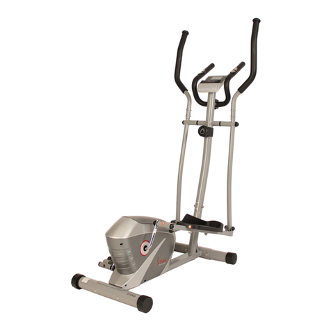
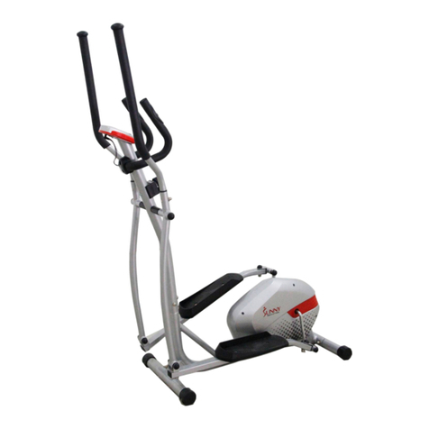
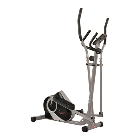
Sunny SF-E905 User manual

MAGNETIC ELLIPTICAL BIKE
SF-E905
USER MANUAL
English, Page 12 ~ 21 IMPORTANT! Please retain owner’s manual for maintenance and adjustment instructions. Your
satisfaction is very important to us, PLEASE DO NOT RETURN UNTIL YOU HAVE
Español, Page 22 ~ 31 ¡IMPORTANTE! Por favor, conserve el manual del usuario para las instrucciones de
mantenimiento y ajuste. Su satisfacción es muy importante para nosotros, SI AL PRODUCTO LE
HACE FALTA PARTES, POR FAVOR NO LO DEVUELVA HASTA TENER CONTACTO CON
Français, Page 32 ~ 41 IMPORTANT! Veuillez conserver le manuel du propriétaire pour les instructions de réglage et
d’entretien. Votre satisfaction est très importante pour nous, VEUILLEZ NE PAS EFFECTUER
877-90SUNNY (877-907-8669).
Deutsch, Seite 42 ~ 51 WICHTIG! Bitte bewahren Sie das Benutzerhandbuch für Wartungs- und Einstellanweisungen
auf. Ihre Zufriedenheit ist besonders wichtig für uns, BITTE SCHICKEN SIE DAS PRODUKT
NICHT ZURÜCK, BEVOR SIE SICH MIT UNS IN VERBINDUNG GESETZT HABEN:
Italiano, Pagina 52~61 IMPORTANTE! Conservare il manuale utente per le istruzioni di manutenzione e regolazione. La
vostra soddisfazione èmolto importante per noi, VI PREGHIAMO DI NON EFFETTUARE RESI
90SUNNY.

1
IMPORTANT SAFETY INFORMATION
We thank you for choosing our product. To ensure your safety and health, please use this equipment correctly. It is important
to read this entire manual before assembling and using the equipment. Safe and effective use can only be achieved if the
equipment is assembled, maintained and used properly. It is your responsibility to ensure that all users of the equipment are
informed of all warnings and precautions.
1. Before starting any exercise program, you should consult your physician to determine if you have any medical or physical
conditions that could put your health and safety at risk, or prevent you from using the equipment properly. Your physician’s
advice is essential if you are taking medication that affects your heart rate, blood pressure or cholesterol level.
2. Be aware of your body’s signals. Incorrect or excessive exercise can damage your health. Stop exercising if you
experience any of the following symptoms: pain, tightness in your chest, irregular heartbeat, shortness of breath,
lightheadedness, dizziness or feelings of nausea. If you do experience any of these conditions, you should consult your
physician before continuing with your exercise program.
3. Keep children and pets away from the equipment. The equipment is designed for adult use only.
4. Use the equipment on a solid, flat level surface with a protective cover for your floor or carpet. To ensure safety, the
equipment should have at least 2 feet (60 cm) of free space all around it.
5. Ensure that all nuts and bolts are securely tightened before using the equipment. The safety of the equipment can only
be maintained if it is regularly examined for damage and/or wear and tear.
6. Always use the equipmentas indicated. If you find any defective components whileassembling or checking the equipment,
or if you hear any unusual noises coming from the equipment during exercise, discontinue use of the equipment
immediately and do not use until the problem has been rectified.
7. Wear suitable clothing while using the equipment. Avoid wearing loose clothing that may become entangled in the
equipment.
8. Do not place fingers or objects into the moving parts of the equipment.
9. The maximum weight capacity of this unit is 220 lbs (100 kgs).
10. The equipment is not suitable for therapeutic use.
11. To avoid bodily injury and/or damage to the product or property, proper lifting and moving is required.
12. Your product is intended for use in cool, dry conditions. You should avoid storage in extreme cold, hot or damp areas as
this may lead to corrosion and other related problems.
13. This equipment is designed for indoor and home use only. It is not intended for commercial use!
INFORMACIÓN IMPORTANTE DE SEGURIDAD
Gracias por haber elegido nuestro producto. Para garantizar su seguridad y salud, utilice este equipo correctamente. Es
importante leer todo el manual antes de instalar y usar el equipo. Solo se puede garantizar el uso seguro y eficaz del equipo
si se instala, mantiene y utiliza correctamente. Es su responsabilidad asegurarse de que todos los usuarios de los equipos
conozcan todas las advertencias y precauciones.
1. Antes de comenzar cualquier programa de ejercicios, consulta con su médico para determinar si tiene alguna condición
médica o física que puede poner en riesgo su salud y seguridad o que podría impedir que utilice el equipo
adecuadamente. El consejo de su médico es esencial en caso de que esté tomando algún medicamento que podría
afectar su ritmo cardíaco, presión arterial o nivel de colesterol.
2. Esté atento a las señales de su cuerpo. Ejercitarse de manera incorrecta o excesiva puede dañar su salud. Deje de
hacer ejercicio si experimenta alguno de los siguientes síntomas: dolor, opresión en el pecho, latidos cardíacos
irregulares, falta de aliento, sensación de desmayo, mareos o sensación de náuseas. Si presenta alguna de esas
condiciones, consulta con su médico antes de continuar con su programa de ejercicios.
3. Mantenga el equipo lejos del alcance de niños y mascotas. El equipo está diseñado para el uso exclusivo de adultos.
4. Utilice el equipo en una superficie plana y sólida con una cubierta protectora para su piso o alfombra. Para garantizar
su seguridad, el equipo debe tener al menos 2 pies (60 cm) de espacio libre a su alrededor.
5. Asegúrese de que todas las tuercas y pernos estén bien ajustados antes de usar el equipo. Solo puede conservarse la
seguridad del equipo si se inspecciona regularmente para detectar daños o desgaste.
6. Siempre utilice el equipo como se indica. Si encuentra algún componente defectuoso mientras instala o revisa el equipo,
o si escucha ruidos extraños que provienen del equipo durante el ejercicio, deje de utilizarlo inmediatamente y no lo
utilice hasta que el problema se ha corregido.
7. Use ropa adecuada cuando utilice el equipo. Evite usar ropa suelta que pueda enredarse en el equipo.
8. No coloque los dedos u objetos en las partes móviles del equipo.
9. La capacidad máxima de peso de esta unidad es de 220 libras (100 kgs).
10. El equipo no es adecuado para uso terapéutico.
11. Muévase con cuidado cuando levante y mueva el equipo a fin de que no se dañe la espalda. Siempre utilice la técnica
de levantamiento adecuada y pida ayuda en caso de que sea necesario.
12. Su producto está diseñado para usar en condiciones frescas y secas. Debe evitar de tenerlo en lugares extremadamente
frías, calientes o húmedas, ya que pueden provocar corrosión y otros problemas relacionados.
13. ¡Este equipo está diseñado solamente para uso interior! ¡No es para uso comercial!

2
INFORMATIONS DE SÉCURITÉIMPORTANTES
Nous vous remercions d’avoir choisi notre produit. Pour votre santé et votre sécurité, veuillez utiliser correctement cet appareil.
Il est important de lire entièrement le présent manuel avant d’assembler l’appareil et de l’utiliser. L’utilisation sûre et efficace
n’est possible que si l’appareil est correctement assemblé, entretenu et utilisé. Il vous incombe de vous assurer que tous les
utilisateurs de l’appareil soient informés de tous les avertissements et précautions.
1. Avant d’entamer un programme d’exercices, consultez votre médecin pour déterminer si vous avez une quelconque
disposition physique ou médicale susceptible de mettre en danger votre santéet votre sécuritéou de vous empêcher
d’utiliser cet appareil correctement. L’avis de votre médecin est essentiel si vous prenez un médicament pouvant affecter
le rythme cardiaque, la pression ou le niveau de cholestérol.
2. Soyez à l’écoute des signaux de votre corps. Accompli de façon incorrecte ou excessive, l’exercice peut nuire à la santé.
Cessez de faire de l’exercice si vous ressentez l’un des symptômes suivants: douleur, serrement de la poitrine, rythme
cardiaque irrégulier, souffle court, étourdissement, vertige, ou sensations de nausée. Si vous éprouvez l’un de ces états,
consultez votre médecin avant de poursuivre votre programme d’exercice.
3. Gardez les enfants et les animaux de compagnie àdistance de l’appareil. L’appareil est conçu pour l’utilisation exclusive
par des adultes.
4. Utilisez l’appareil sur une surface dure, plane et de niveau, avec une protection pour votre parquet ou tapis. Pour un
usage sûr, l’appareil doit disposer d’au moins 60 cm (2 pi) d’espace libre tout autour de lui.
5. Assurez-vous que tous les boulons et écrous soient bien serrés avant d’utiliser l’appareil. La sécurité de l’appareil ne peut
être entretenue qu’à condition de régulièrement vérifier l’absence de dommages ou d’usure.
6. Utilisez toujours l’appareil comme indiqué. Si vous trouvez un composant défectueux lors de l’assemblage ou de la
vérification de l’appareil, ou si vous entendez un bruit inhabituel en provenir pendant l’utilisation, cessez immédiatement
l’exercice et n’employez plus l’appareil tant que le problème n’a pas été résolu.
7. Portez des vêtements adéquats lors de l’utilisation de l’appareil. Évitez les vêtements amples qui risqueraient de se
prendre dans l’appareil.
8. Ne mettez pas le doigt ni aucun objet dans les pièces mobiles de l’appareil.
9. La capacitéde poids maximale de cet appareil est de 100 kgs (220 lbs).
10. Cet appareil n’est pas adapté à un usage thérapeutique.
11. Soulevez et déplacez l’appareil avec précaution. Utilisez toujours les techniques adéquates de levage et demandez de
l’aide si nécessaire.
12. Votre produit est conçu pour usage dans un endroit sec et frais. Éviter de l’entreposer dans un endroit extrêmement froid,
chaud ou humide, car cela peut entraîner de la corrosion et des problèmes du même ordre.
13. Cet appareil est conçu pour un usage intérieur uniquement! Il n’est pas fait pour une utilisation commerciale!
WICHTIGE SICHERHEITSHINWEISE
Wir danken Ihnen, dass Sie sich für unser Produkt entschieden haben. Zur Gewährleistung Ihrer Sicherheit und Gesundheit
verwenden Sie dieses Gerät bitte ordnungsgemäß. Es ist wichtig, diese gesamte Bedienungsanleitung zu lesen, bevor Sie
das Gerät montieren und in Betrieb nehmen. Eine sichere und effektive Nutzung kann nur erreicht werden, wenn das Gerät
ordnungsgemäßmontiert, gewartet und verwendet wird. Sie sind dafür verantwortlich, dass alle Benutzer des Geräts über
alle Warnungen und Vorsichtsmaßnahmen informiert werden.
1. Vor Beginn eines jeden Trainingsprogramms ist es ratsam, einen Arzt zu konsultieren, um festzustellen, ob Sie
medizinische oder körperliche Beschwerden haben, die Ihre Gesundheit und Sicherheit gefährden oder verhindern
könnten, dass Sie das Gerät ordnungsgemäßbenutzen. Der Rat Ihres Arztes ist unerlässlich, wenn Sie Medikamente
einnehmen, die Ihre Herzfrequenz, Ihren Blutdruck oder Ihren Cholesterinspiegel beeinflussen.
2. Achten Sie auf die Signale Ihres Körpers. Falsches oder übermäßiges Training kann Ihre Gesundheit schädigen. Hören
Sie auf zu trainieren, wenn Sie eines der folgenden Symptome verspüren: Schmerzen, Engegefühl in Ihrer Brust,
unregelmäßiger Herzschlag, Kurzatmigkeit, Benommenheit, Schwindel oder Übelkeit. Wenn Sie einen dieser Zustände
bemerken, sollten Sie Ihren Arzt konsultieren, bevor Sie mit Ihrem Trainingsprogramm fortfahren.
3. Kinder und Haustiere dürfen nicht in der Nähe des Geräts sein. Das Gerät ist nur für den Gebrauch durch Erwachsene
bestimmt.
4. Verwenden Sie das Gerät auf einer festen, ebenen Fläche mit einer Schutzabdeckung für Ihren Boden oder Teppich.
Um die Sicherheit zu gewährleisten, sollte das Gerät ringsum mindestens 2 Fuß(60 cm) Freiraum haben.
5. Vergewissern Sie sich, dass alle Muttern und Bolzen fest angezogen sind, bevor Sie das Gerät benutzen. Die Sicherheit
des Gerätes kann nur gewährleistet werden, wenn es regelmäßig auf Beschädigungen und/oder Verschleißüberprüft
wird.
6. Verwenden Sie das Gerät immer entsprechend den Angaben. Wenn Sie bei der Montage oder Überprüfung des Geräts
defekte Komponenten feststellen oder ungewöhnliche Geräusche vom Gerät während des Trainings hören, stellen Sie
die Verwendung des Geräts sofort ein. In diesem Fall sollten Sie es erst dann wieder in Betrieb nehmen, wenn das
Problem behoben ist.
7. Tragen Sie bei der Benutzung des Gerätes geeignete Kleidung. Vermeiden Sie das Tragen von loser Kleidung, die sich
in der Ausrüstung verfangen kann.
8. Stecken Sie keine Finger oder Gegenstände in die beweglichen Teile des Gerätes.
9. Die maximale Gewichtsbelastbarkeit dieser Einheit beträgt 220 Pfund (100 kgs).
10. Dieses Gerät ist nicht für den therapeutischen Einsatz geeignet.
11. Um Personenschäden und/oder Schäden am Produkt oder Eigentum zu vermeiden, ist ein ordnungsgemäßes
Hochheben und Transportieren erforderlich.
12. Ihr Produkt ist für den Einsatz unter kühlen und trockenen Bedingungen bestimmt. Sie sollten die Lagerung in extrem
kalten, heißen oder feuchten Räumen vermeiden, da dies zu Korrosion und anderen damit verbundenen Problemen
führen kann.
13. Dieses Gerät ist nur für den Innen- und Heimgebrauch bestimmt; es ist nicht für die gewerbliche Nutzung bestimmt.
3
IMPORTANTI INFORMAZIONI SULLA SICUREZZA
Vi ringraziamo per aver scelto il nostro prodotto. Per garantire la vostra sicurezza e la vostra salute, vi invitiamo a utilizzare
questa apparecchiatura in modo corretto. Prima di assemblare e utilizzare l'apparecchiatura, è importante leggere il presente
manuale per intero. Un utilizzo sicuro ed efficace è possibile solo se l'apparecchiatura viene assemblata, sottoposta a
manutenzione e utilizzata correttamente. È responsabilità dell'utente assicurarsi che tutti gli utilizzatori dell'apparecchiatura
siano informati di tutte le avvertenze e precauzioni.
1. Prima di iniziare qualsiasi programma di esercizio, è necessario consultare il proprio medico per determinare se esistono
condizioni mediche o fisiche che potrebbero mettere a rischio la salute e la sicurezza o impedire un uso corretto
dell'apparecchiatura. Il parere del medico è essenziale se si assumono farmaci che influiscono sulla frequenza cardiaca,
sulla pressione sanguigna o sul livello di colesterolo.
2. Siate consapevoli dei segnali del vostro corpo. Un esercizio scorretto o eccessivo può danneggiare la salute. Interrompete
l'esercizio se avvertite uno dei seguenti sintomi: dolore, senso di oppressione al petto, battito cardiaco irregolare,
mancanza di respiro, giramenti di testa, vertigini o senso di nausea. Se si verifica una di queste condizioni, è necessario
consultare il medico prima di continuare il programma di esercizio.
3. Tenere i bambini e gli animali domestici lontani dall'attrezzo. L'attrezzatura è progettata solo per l'uso da parte di adulti.
4. Utilizzare l'attrezzo su una superficie solida e piana, con una copertura protettiva per il pavimento o il tappeto. Per
garantire la sicurezza, l'apparecchiatura deve avere almeno 2 piedi (60 cm) di spazio libero intorno a sé.
5. Prima di utilizzare l'apparecchiatura, accertarsi che tutti i dadi e i bulloni siano ben serrati. La sicurezza
dell'apparecchiatura può essere mantenuta solo se viene esaminata regolarmente per verificare l'assenza di danni e/o
usura.
6. Utilizzare sempre l'apparecchiatura come indicato. Se durante l'assemblaggio o il controllo dell'attrezzatura si riscontrano
componenti difettosi o se si sentono rumori insoliti provenire dall'attrezzatura durante l'esercizio, interrompere
immediatamente l'uso dell'attrezzatura e non utilizzarla fino a quando il problema non è stato risolto.
7. Indossare un abbigliamento adeguato durante l'uso dell'apparecchiatura. Evitare di indossare indumenti larghi che
potrebbero impigliarsi nell'apparecchiatura.
8. Non inserire dita o oggetti nelle parti mobili dell'apparecchiatura.
9. La capacità massima di peso di questa unità è di 100 kgs (220 lbs).
10. Questa apparecchiatura non è adatta all'uso terapeutico.
11. Per evitare lesioni fisiche e/o danni al prodotto o alle cose, è necessario sollevare e spostare l'apparecchio in modo
corretto.
12. Il prodotto è destinato all'uso in ambienti freschi e asciutti. Si consiglia di evitare lo stoccaggio in ambienti estremamente
freddi, caldi o umidi, poiché ciò potrebbe causare corrosione e altri problemi correlati.
13. Questa apparecchiatura è progettata solo per l'uso domestico e interno; non è destinata all'uso commerciale.

4
EXPLODED DIAGRAM 1

5
EXPLODED DIAGRAM 2
HARDWARE PACKAGE
#102 S8 1PC
#101 S6 1PC
#49L/R Φ16x85 1PR.
#37 M8x40 4PCS
#28 M10xL45 4PCS
#99 S13,S14 2PCS
#100 S17,S19 2PCS
#29 d10x1.5 4PCS
#30 M10 4PCS
#14 Φ20xd8.5xR25 4PCS
#33 M8 4PCS
#39 Φ13xB2 2PCS
#40L/R B0.5x20 1PR.
#61 Φ17.1xΦ23x0.3 2PCS

6
PARTS LIST
No.
Description
Spec.
Qty.
No.
Description
Spec.
Qty.
1
Main Frame
1
51
Hex Bolt
M10x50
2
2
Front Stabilizer
1
52
Crank Arm
140x228, thickness
16mm, Black
1
3
Rear Stabilizer
1
53
Axle Bushing 1
Φ24x16xΦ16.1
4
4
Roller Cap
Φ50
2
54
Flat Washer
d10x1.5 (Nickel)
2
5
Leveler Cap
Φ50
2
55
Alloy Bushing
Φ14x12.5xΦ10.1
4
6
Carriage Bolt
M10xL57
4
56
Nylon Nut
M10
2
7
Arc Washer
Φ10x1.5xΦ25xR28
4
57
Nut Cap
S19
2
8
Domed Nut
M10
4
58
Nut Cap
S14
4
9
Handlebar Post
1
59
Spacer
Φ32x59
2
10a
Tension Controller
8 levels
1
60
Axle Bushing 2
Φ32x2.5
4
10b
Tension Cable
1
61
Wave Washer
Φ17.1xΦ23x0.3
2
11
Phillips Screw
M5x45
1
62
Plastic Nut
S17
1
12
Flat Washer
D5
1
63
Plug
Φ13x1.5
2
13
Allen Bolt
M8x20
4
64
Crank Cover
2
14
Arc Washer
Φ20xd8.5xR25
8
65L/R
Belt Cover
1 PR.
15
Upper Sensor Wire
1000mm
1
66
Nut
4.5x32x32
1
16
Lower Sensor Wire
1200mm
1
67
Washer
Φ22.6xΦ286xΦ33.5
1
17
Tension Hook
1300mm
1
68
Locking Nut-L
Φ456xH3.5xΦ33.5
1
18L/R
Pedal Support Tube
1 PR.
69
Open Face Bearing
Φ45.86x8.8
2
19
Connecting Joint
2
70
Bearing Housing
2.5x766x76
2
20
Nut Cap
S13
2
71
Sensor
1
21
Hex Bolt
M8x55
2
72
Bolt
ST3x10
2
22
Flat Washer
d8x1.5
2
73
Locking Nut-R
Φ456xH3.5xΦ33.5
1
23
Nylon Nut
M8 (Black Color)
2
74
Big Washer
Φ25.26xΦ386x1
1
24L/R
Swing Bar
1 PR.
75
Belt
380PJ6
1
25
Hex Bolt
M8x15
2
76
Belt Pulley
Φ260x20
1
26
Flat Washer
Φ8.2XΦ32X2
2
77
Hex Bolt
M5xL60
1
27L/R
Pedal
1 PR.
78
Hex Nut
M5
2
28
Hex Bolt
M10xL45
4
79
Hex Bolt
M6xL15
2
29
Flat Washer
d10x1.5 (Black Color)
4
80
Spring Washer
D6
2
30
Nylon Nut
M10 (White Color)
4
81
Flat Washer
D6
2
31
Armrest
1
82
Axle Stop Ring
D12
2
32L/R
Handlebar
1 PR.
83
Magnetic Board Axle
Φ12x50
1
33
Domed Nut
M8
4
84
Magnetic Board
1
34
Spring Washer
d8x1.5
2
85
Spring
61xΦ15xΦ1.6
1
35
Hex Bolt
M8x30
2
86
Square Magnet
40x25x10
8
36
Decorative Cover
1
87
Hex Thin Nut
M10x1
2
37
Carriage Bolt
M8x40
4
88
Adjusting Belt Bolt
M6x50
2
38
Meter
JS119B/HT050
1
89
Adjusting U Washer
36x306x20
2
38a
Meter Wire A
150mm
1
90
Hex Nut
M6
2
38b
Meter Wire B
150mm
1
91
Nut
M10x1.0
2
38c
Meter Wire C
150mm
1
92
Bearing
6000z
2
39
Spring Washer
Φ13xB2
2
93
Flywheel Axle
Φ10xL118
1
40L/R
Nylon Nut
B0.5x20
1 PR.
94
Flywheel
Φ200x38
1
41
Nut Cap
S17
4
95
Bolt
ST4.3x20
5
42
Square End Cap
40x25x1.5
2
96
Wave Washer
Φ20xΦ28x0.6
2
43
Foam Grip
Φ23xΦ32x480
2
97
Bolt
ST5x20
4
44
Foam Grip
Φ26xΦ36x480
2
98
Flat Washer
D5x1
4
45
Round End Cap
Φ28x1.5
2
99
Spanner
S13,S14
2
46a
Pulse Sensor Wire A
600mm
1
100
Spanner
S17,S19
2
46b
Pulse Sensor Wire B
600mm
1
101
Allen Wrench
S6
1
47
Spherical Cap
Φ25x1.5
2
102
Allen Wrench
S8
1
48
Mushroom Cap
Φ28.6x1.5
2
103
Pulse Sensor
2
49L/R
Hinge Bolt
Φ16x85
1 PR.
104
Screw
ST4.2x18
2
50
Tension Controller Cover
1

7
LISTA DE PIEZAS
n.°
DESCRIPCIÓN
ESPEC.
CANT.
n.°
DESCRIPCIÓN
ESPEC.
CANT.
1
Estructura Principal
1
51
Perno Hexagonal
M10x50
2
2
Estabilizador Delantero
1
52
Brazo de Biela
140x228, espesor
16mm, Negro
1
3
Estabilizador Trasero
1
53
Buje de Eje 1
Φ24x16xΦ16.1
4
4
Tapa de Rodillo
Φ50
2
54
Arandela Plana
d10x1.5 (Níquel)
2
5
Tapa Niveladora
Φ50
2
55
Buje de Aleación
Φ14x12.5xΦ10.1
4
6
Perno de Carrocería
M10xL57
4
56
Tuerca de Nailon
M10
2
7
Arandela en Arco
Φ10x1.5xΦ25xR28
4
57
Tapa de Tuerca
S19
2
8
Tuerca de Sombrerete
M10
4
58
Tapa de Tuerca
S14
4
9
Poste de Manubrio
1
59
Espaciador
Φ32x59
2
10a
Controlador de Tensión
8 niveles
1
60
Buje de Eje 2
Φ32x2.5
4
10b
Cable de Tensión
1
61
Arandela Ondulada
Φ17.1xΦ23x0.3
2
11
Tornillo Phillips
M5x45
1
62
Tuerca de Plástico
S17
1
12
Arandela Plana
D5
1
63
Clavija
Φ13x1.5
2
13
Perno Allen
M8x20
4
64
Cubierta de Biela
2
14
Arandela en Arco
Φ20xd8.5xR25
8
65L/R
Cubierta de Correa
1 PR.
15
Cable del Sensor
Superior
1000mm
1
66
Tuerca
4.5x32x32
1
16
Cable del Sensor Inferior
1200mm
1
67
Arandela
Φ22.6xΦ286xΦ33.5
1
17
Gancho de Tensión
1300mm
1
68
Tuerca de Bloqueo L
Φ456xH3.5xΦ33.5
1
18L/R
Tubo de Soporte del
Pedal (Izq/Der)
1 PR.
69
Rodamiento de Boca
Abierta
Φ45.86x8.8
2
19
Junta de Conexión
2
70
Cubierta de Cojinete
2.5x766x76
2
20
Tapa de Tuerca
S13
2
71
Sensor
1
21
Perno Hexagonal
M8x55
2
72
Perno
ST3x10
2
22
Arandela Plana
d8x1.5
2
73
Tuerca de Bloqueo R
Φ456xH3.5xΦ33.5
1
23
Tuerca de Nailon
M8 (Color Negro)
2
74
Arandela Grande
Φ25.26xΦ386x1
1
24L/R
Barra de Manubrio
1 PR.
75
Correa
380PJ6
1
25
Perno Hexagonal
M8x15
2
76
Polea de la Correa
Φ260x20
1
26
Arandela Plana
Φ8.2xΦ32x2
2
77
Perno Hexagonal
M5xL60
1
27L/R
Pedal
1 PR.
78
Tuerca Hexagonal
M5
2
28
Perno Hexagonal
M10xL45
4
79
Perno Hexagonal
M6xL15
2
29
Arandela Plana
d10x1.5 (Color Negro)
4
80
Arandela de Presión
D6
2
30
Tuerca de Nylon
M10 (Color Blanco)
4
81
Arandela Plana
D6
2
31
Apoyabrazos
1
82
Anillo del Eje
D12
2
32L/R
Manubrio (Izq/Der)
1 PR.
83
Eje del Tablero Magnético
Φ12x50
1
33
Tuerca de Sombrerete
M8
4
84
Tablero Magnético
1
34
Arandela de Presión
d8x1.5
2
85
Resorte
61xΦ15xΦ1.6
1
35
Perno Hexagonal
M8x30
2
86
Imán Cuadrado
40x25x10
8
36
Cubierta Decorativa
1
87
Tuerca Delgada
Hexagonal
M10x1
2
37
Perno de Carrocería
M8x40
4
88
Perno de Ajuste de la
Cadena
M6x50
2
38
Medidor
JS119B/HT050
1
89
Arandela de Ajuste en U
36x306x20
2
38a
Cable del Medidor A
150mm
1
90
Tuerca Hexagonal
M6
2
38b
Cable del Medidor B
150mm
1
91
Tuerca
M10x1.0
2
38c
Cable del Medidor C
150mm
1
92
Cojinete
6000z
2
39
Arandela de Presión
Φ13xB2
2
93
Eje del Volante
Φ10xL118
1
40L/R
Tuerca de Nailon
B0.5x20
1 PR.
94
Volante de Inercia
Φ200x38
1
41
Tapa de Tuerca
S17
4
95
Perno
ST4.3x20
5
42
Tapa del Extremo
Rectangular
40x25x1.5
2
96
Arandela Ondulada
Φ20xΦ28x0.6
2
43
Agarre de Espuma
Φ23xΦ32x480
2
97
Perno
ST5x20
4
44
Agarre de Espuma
Φ26xΦ36x480
2
98
Arandela Plana
D5x1
4
45
Tapa de Extremo Circular
Φ28x1.5
2
99
Llave Inglesa
S13,S14
2
46a
Cable del Sensor de
Pulso A
600mm
1
100
Llave Inglesa
S17,S19
2
46b
Cable del Sensor de
Pulso B
600mm
1
101
Llave Allen
S6
1
47
Tapa Redonda
Φ25x1.5
2
102
Llave Allen
S8
1
48
Tapa Redonda
Φ28.6x1.5
2
103
Sensor del Pulso de Mano
2
49L/R
Perno de la Bisagra
(Izq/Der)
Φ16x85
1 PR.
104
Tornillo
ST4.2x18
2
50
Cubierta del Controlador
de Tensión
1

8
LISTE DES ÉLÉMENTS
No
DESCRIPTION
SPÉCIFICATION
QTÉ
No
DESCRIPTION
SPÉCIFICATION
QTÉ
1
Cadre Principal
1
51
Boulon Hexagonal
M10x50
2
2
Stabilisateur Avant
1
52
Bras de Manivelle
140x228,
l'épaisseur 16mm,
Noire
1
3
Stabilisateur Arrière
1
53
Bague de l’Axe 1
Φ24x16xΦ16.1
4
4
Capuchon Stabilisateur Avant
Φ50
2
54
Rondelle Plate
d10x1,5 (Nickel)
2
5
Capuchon de Nivellement
Φ50
2
55
Bague en Alliage
Φ14x12.5xΦ10.1
4
6
Boulon de Carrosserie
M10xL57
4
56
Écrou de Nylon
M10
2
7
Rondelle Cintrée
Φ10x1,5xΦ25xR28
4
57
Capuchon d’Écrou
S19
2
8
Écrou Dôme
M10
4
58
Capuchon d’Écrou
S14
4
9
Tige de Guidon
1
59
Bague d’Espacement
Φ32x59
2
10a
Contrôleur de Tension
8 niveaux
1
60
Bague de l’Axe 2
Φ32x2.5
4
10b
Câble de Tension
1
61
Rondelle Ondulée
Φ17,1xΦ23x0,3
2
11
Vis Cruciforme
M5x45
1
62
Écrou en Plastique
S17
1
12
Rondelle Plate
D5
1
63
Bouchon
Φ13x1.5
2
13
Boulon Allen
M8x20
4
64
Carter de Manivelle
2
14
Rondelle Cintrée
Φ20xd8,5xR25
8
65L/R
Couvercle de Courroie
1 paire
15
Câble Supérieur du Capteur
1000mm
1
66
Écrou
4.5x32x32
1
16
Câble Inférieur du Capteur
1200mm
1
67
Rondelle
Φ22.6xΦ286xΦ33.
5
1
17
Crochet de Tension
1300mm
1
68
Contre-écrou-G
Φ456xH3.5xΦ33.5
1
18L/R
Tube de Support de la Pédale
1 paire
69
Roulement Ouvert
Φ45.86x8.8
2
19
Joint de Connexion
2
70
Boîtier de Roulement
2.5x766x76
2
20
Capuchon d’Écrou
S13
2
71
Capteur
1
21
Boulon Hexagonal
M8x55
2
72
Boulon
ST3x10
2
22
Rondelle Plate
d8x1,5
2
73
Contre-écrou-D
Φ456xH3.5xΦ33.5
1
23
Écrou de Nylon
M8 (Couleur Noire)
2
74
Grande Rondelle
Φ25.26xΦ386x1
1
24L/R
Guidon Mobile
1 paire
75
Courroie
380PJ6
1
25
Boulon Hexagonal
M8x15
2
76
Poulie de la Courroie
Φ260x20
1
26
Rondelle Plate
Φ8,2xΦ32x2
2
77
Boulon Hexagonal
M5xL60
1
27L/R
Pédale
1 paire
78
Écrou Hexagonal
M5
2
28
Boulon Hexagonal
M10xL45
4
79
Boulon Hexagonal
M6xL15
2
29
Rondelle Plate
d10x1,5 (Couleur
Noire)
4
80
Rondelle àRessort
D6
2
30
Écrou de Nylon
M10 (Couleur
Blanche)
4
81
Rondelle Plate
D6
2
31
Accoudoir
1
82
Anneau de Butée d’Axe
D12
2
32L/R
Guidon
1 paire
83
Axe du Panneau de Force
Magnétique
Φ12x50
1
33
Écrou Dôme
M8
4
84
Panneau Magnétique
1
34
Rondelle àRessort
d8x1,5
2
85
Ressort
61xΦ15xΦ1.6
1
35
Boulon Hexagonal
M8x30
2
86
Aimant Carré
40x25x10
8
36
Cache Décoratif
1
87
Écrou Hexagonal Mince
M10x1
2
37
Boulon de Carrosserie
M8x40
4
88
Boulon de Réglage de la
Chaîne
M6x50
2
38
Compteur
JS119B/HT050
1
89
Rondelle de Réglage en
Forme de U
36x306x20
2
38a
Câble du Compteur A
150mm
1
90
Écrou Hexagonal
M6
2
38b
Câble du Compteur B
150mm
1
91
Écrou
M10x1,0
2
38c
Câble du Compteur C
150mm
1
92
Roulement
6000z
2
39
Rondelle àRessort
Φ13xB2
2
93
Axe du Volant d’Inertie
Φ10xL118
1
40L/R
Écrou de Nylon
B0,5x20
1 paire
94
Volant d’Inertie
Φ200x38
1
41
Capuchon d’Écrou
S17
4
95
Boulon
ST4,3x20
5
42
Embout d’ExtrémitéCarré
40x25x1.5
2
96
Rondelle Ondulée
Φ20xΦ28x0.6
2
43
Poignée en Mousse
Φ23xΦ32x480
2
97
Boulon
ST5x20
4
44
Poignée en Mousse
Φ26xΦ36x480
2
98
Rondelle Plate
D5x1
4
45
Embout d’ExtrémitéArrondi
Φ28x1.5
2
99
CléTricoise
S13,S14
2
46a
Câble du Capteur de Pouls A
600mm
1
100
CléTricoise
S17,S19
2
46b
Câble du Capteur de Pouls B
600mm
1
101
CléAllen
S6
1
47
Capuchon Sphérique
Φ25x1.5
2
102
CléAllen
S8
1
48
Capuchon Champignon
Φ28.6x1.5
2
103
Capteur de Pouls
2
49L/R
Boulon de Charnière
Φ16x85
1 paire
104
Vis
ST4,2x18
2
50
Carter du Contrôleur de Tension
1

9
TEILELISTE
Nr.
Bezeichnung
Spezif.
Menge
Nr.
Bezeichnung
Spezif.
Menge
1
Hauptrahmen
1
51
Sechskantschraube
M10x50
2
2
Stabilisator Vorne
1
52
Kurbelarm
140x228, Dicke
16mm, schwarz
1
3
Stabilisator Hinten
1
53
Axenbuchse 1
Φ24x16xΦ16.1
4
4
Rollenkappe
Φ50
2
54
Unterlegscheibe
d10x1,5 (Nickel)
2
5
Nivellierkappe
Φ50
2
55
Metallbuchse
Φ14x12.5xΦ10.1
4
6
Schlossschraube
M10xL57
4
56
Nylonmutter
M10
2
7
Gewölbte Federscheibe
Φ10x1,5xΦ25xR28
4
57
Mutternkappe
S19
2
8
Hutmutter
M10
4
58
Mutternkappe
S14
4
9
Lenkerstütze
1
59
Abstandhalter
Φ32x59
2
10a
Spannungsregler
8 Ebenen
1
60
Axenbuchse 2
Φ32x2.5
4
10b
Zugkabel
1
61
Wellenscheibe
Φ17,1xΦ23x0,3
2
11
Kreuzschraube
M5x45
1
62
Kunststoffmutter
S17
1
12
Unterlegscheibe
D5
1
63
Stecker
Φ13x1.5
2
13
Inbusschraube
M8x20
4
64
Kurbelabdeckung
2
14
Gewölbte Federscheibe
Φ20xd8,5xR25
8
65L/R
Kettenabdeckung
1 P.
15
Oberer Sensordraht
1000mm
1
66
Schraubenmutter
4.5x32x32
1
16
Unterer Sensordraht
1200mm
1
67
Beilagscheibe
Φ22.6xΦ286xΦ33.5
1
17
Zughaken
1300mm
1
68
Kontermutter-L
Φ456xH3.5xΦ33.5
1
18L/R
Pedalstützrohr
1 P.
69
Offenes Kugellager
Φ45.86x8.8
2
19
Verbindungsgelenk
2
70
Lagergehäuse
2.5x766x76
2
20
Mutternkappe
S13
2
71
Sensor
1
21
Sechskantschraube
M8x55
2
72
Bolzen
ST3x10
2
22
Unterlegscheibe
d8x1,5
2
73
Kontermutter-R
Φ456xH3.5xΦ33.5
1
23
Nylonmutter
M8 (Schwarze Farbe)
2
74
Große Beilagscheibe
Φ25.26xΦ386x1
1
24L/R
Schwenkstange
1 P.
75
Riemen
380PJ6
1
25
Sechskantschraube
M8x15
2
76
Riemenscheibe
Φ260x20
1
26
Unterlegscheibe
Φ8,2xΦ32x2
2
77
Sechskantschraube
M5xL60
1
27L/R
Pedal
1 P.
78
Sechskantmutter
M5
2
28
Sechskantschraube
M10xL45
4
79
Sechskantschraube
M6xL15
2
29
Unterlegscheibe
d10x1,5 (Schwarze
Farbe)
4
80
Federscheibe
D6
2
30
Nylonmutter
M10 (Weiße Farbe)
4
81
Unterlegscheibe
D6
2
31
Armstütze
1
82
Achsanschlagring
D12
2
32L/R
Griffstange
1 P.
83
Magnetplatinenachse
Φ12x50
1
33
Hutmutter
M8
4
84
Platinenachse
1
34
Federscheibe
d8x1,5
2
85
Sprungfeder
61xΦ15xΦ1.6
1
35
Sechskantschraube
M8x30
2
86
Vierkant-Magnet
40x25x10
8
36
Dekorative Abdeckung
1
87
Flache Sechskantmutter
M10x1
2
37
Schlossschraube
M8x40
4
88
Kettenbolzeneinsteller
M6x50
2
38
Zähler
JS119B/HT050
1
89
U-Scheibe-Einsteller
36x306x20
2
38a
Zählerdraht A
150mm
1
90
Sechskantmutter
M6
2
38b
Zählerdraht B
150mm
1
91
Schraubenmutter
M10x1,0
2
38c
Zählerdraht C
150mm
1
92
Kugellager
6000z
2
39
Federscheibe
Φ13xB2
2
93
Schwungradachse
Φ10xL118
1
40L/R
Nylonmutter
B0,5x20
1 P.
94
Schwungrad
Φ200x38
1
41
Mutternkappe
S17
4
95
Bolzen
ST4,3x20
5
42
Vierkant-Endkappe
40x25x1.5
2
96
Wellenscheibe
Φ20xΦ28x0.6
2
43
Schaumstoffgriff
Φ23xΦ32x480
2
97
Bolzen
ST5x20
4
44
Schaumstoffgriff
Φ26xΦ36x480
2
98
Unterlegscheibe
D5x1
4
45
Runde Endkappe
Φ28x1.5
2
99
Schraubenschlüssel
S13,S14
2
46a
Pulssensordraht A
600mm
1
100
Schraubenschlüssel
S17,S19
2
46b
Pulssensordraht B
600mm
1
101
Inbusschlüssel
S6
1
47
Kugelkappe
Φ25x1.5
2
102
Inbusschlüssel
S8
1
48
Pilzkappe
Φ28.6x1.5
2
103
Handpulssensor
2
49L/R
Scharnierbolzen
Φ16x85
1 P.
104
Schraube
ST4,2x18
2
50
Spannungsregler-Abdeckung
1

10
ELENCO PARTI
n.
Descrizione
Spec.
Qtà.
n.
Descrizione
Spec.
Qtà.
1
Telaio Principale
1
51
Bullone Esagonale
M10x50
2
2
Stabilizzatore Anteriore
1
52
Braccio a Manovella
140x228, spessore
16mm, Nero
1
3
Stabilizzatore Posteriore
1
53
Boccola dell'Asse 1
Φ24x16xΦ16.1
4
4
Tappo del Rullo
Φ50
2
54
Rondella Piatta
d10x1.5 (Nichel)
2
5
Tappo Livellatore
Φ50
2
55
Boccola in Lega
Φ14x12.5xΦ10.1
4
6
Bullone del Carrello
M10xL57
4
56
Dado in Nylon
M10
2
7
Rondella ad Arco
Φ10x1.5xΦ25xR28
4
57
Cappuccio del Dado
S19
2
8
Dado Bombato
M10
4
58
Cappuccio del Dado
S14
4
9
Palo del Manubrio
1
59
Distanziale
Φ32x59
2
10a
Controllore di Tensione
8 livelli
1
60
Boccola Dell'asse 2
Φ32x2.5
4
10b
Cavo di Tensione
1
61
Rondella a Onda
Φ17.1xΦ23x0.3
2
11
Vite a Croce
M5x45
1
62
Dado di Plastica
S17
1
12
Rondella Piatta
D5
1
63
Tappo
Φ13x1.5
2
13
Bullone a Brugola
M8x20
4
64
Coperchio della Manovella
2
14
Rondella ad Arco
Φ20xd8.5xR25
8
65L/R
Coperchio della Cinghia
1 PR.
15
Filo del Sensore Superiore
1000mm
1
66
Dado
4.5x32x32
1
16
Filo del Sensore Inferiore
1200mm
1
67
Rondella
Φ22.6xΦ286xΦ33.5
1
17
Gancio di Tensione
1300mm
1
68
Dado di Bloccaggio-L
Φ456xH3.5xΦ33.5
1
18L/R
Tubo di Supporto del
Pedale
1 PR.
69
Cuscinetto a Faccia Aperta
Φ45.86x8.8
2
19
Giunto di Collegamento
2
70
Alloggiamento Cuscinetto
2.5x766x76
2
20
Cappuccio del Dado
S13
2
71
Sensore
1
21
Bullone Esagonale
M8x55
2
72
Bullone
ST3x10
2
22
Rondella Piatta
d8x1.5
2
73
Dado di Bloccaggio-R
Φ456xH3.5xΦ33.5
1
23
Dado in Nylon
M8 (Colore Nero)
2
74
Rondella Grande
Φ25.26xΦ386x1
1
24L/R
Barra Oscillante
1 PR.
75
Cinghia
380PJ6
1
25
Bullone Esagonale
M8x15
2
76
Puleggia Della Cinghia
Φ260x20
1
26
Rondella Piatta
Φ8.2xΦ32x2
2
77
Bullone Esagonale
M5xL60
1
27L/R
Pedale
1 PR.
78
Dado Esagonale
M5
2
28
Bullone Esagonale
M10xL45
4
79
Bullone Esagonale
M6xL15
2
29
Rondella Piatta
d10x1.5 (Colore Nero)
4
80
Rondella Elastica
D6
2
30
Dado in Nylon
M10 (Colore Bianco)
4
81
Rondella Piatta
D6
2
31
Bracciolo
1
82
Anello di Arresto dell'Asse
D12
2
32L/R
Manubrio
1 PR.
83
Asse Della Lavagna Magnetica
Φ12x50
1
33
Dado Bombato
M8
4
84
Lavagna Magnetica
1
34
Rondella a Molla
d8x1.5
2
85
Molla
61xΦ15xΦ1.6
1
35
Bullone Esagonale
M8x30
2
86
Magnete Quadrato
40x25x10
8
36
Copertura Decorativa
1
87
Dado Sottile Esagonale
M10x1
2
37
Bullone del Carrello
M8x40
4
88
Bullone di Regolazione della
Cinghia
M6x50
2
38
Contatore
JS119B/HT050
1
89
Rondella a U di Regolazione
36x306x20
2
38a
Filo del Contatore A
150mm
1
90
Dado Esagonale
M6
2
38b
Filo del Contatore B
150mm
1
91
Dado
M10x1.0
2
38c
Filo del Contatore C
150mm
1
92
Cuscinetto
6000z
2
39
Rondella a Molla
Φ13xB2
2
93
Asse del Volano
Φ10xL118
1
40L/R
Dado in Nylon
B0.5x20
1 PR.
94
Volano
Φ200x38
1
41
Cappuccio del Dado
S17
4
95
Bullone
ST4.3x20
5
42
Tappo Terminale Quadrato
40x25x1.5
2
96
Rondella a Onda
Φ20xΦ28x0.6
2
43
Impugnatura in Schiuma
Φ23xΦ32x480
2
97
Bullone
ST5x20
4
44
Grip in Schiuma
Φ23xΦ36x480
2
98
Rondella Piatta
D5x1
4
45
Tappo Terminale Rotondo
Φ28x1.5
2
99
Chiave
S13,S14
2
46a
Filo del Sensore di Impulsi
A
600mm
1
100
Chiave
S17,S19
2
46b
Filo del Sensore di Impulsi
B
600mm
1
101
Chiave
S6
1
47
Cappuccio Sferico
Φ25x1.5
2
102
Chiave
S8
1
48
Tappo a Fungo
Φ28.6x1.5
2
103
Sensore Pulsazioni
2
49L/R
Bullone a Cerniera
Φ16X85
1 PR.
104
Vite
ST4.2x18
2
50
Coperchio del Regolatore
di Tensione
1

11
Ordering Replacement Parts (U.S. and Canadian Customers only)
Please provide the following information in order for us to accurately identify the part(s) needed:
✓The model number (found on cover of manual)
✓The product name (found on cover of manual)
✓The part number found on the “EXPLODED DIAGRAM” (pages 4-5) and “PARTS LIST” (page 6)
Please contact us at support@sunnyhealthfitness.com or 1-877-90SUNNY (877-907-8669).
Pedido de piezas de repuesto (solo para clientes de EE. UU. y Canadá)
Proporcione la siguiente información para que podamos identificar con precisión las piezas
necesarias:
✓El número de modelo (se encuentra en la portada del manual).
✓El nombre del producto (se encuentra en la portada del manual).
✓El número de pieza que se encuentra en el “ESQUEMA DE LAS PIEZAS” (pages 4-5) y en la
“LISTA DE PIEZAS” (page 7).
Contáctenos en support@sunnyhealthfitness.com o 1-877-90SUNNY (877-907-8669).
Pour commander des pièces de rechange (clients américains et canadiens seulement)
Veuillez fournir les informations suivantes afin que nous puissions identifier avec précision la pièce ou
les pièces requise(s):
✓Le numéro de modèle (situésur la couverture du manuel)
✓Le nom du produit (situésur la couverture du manuel)
✓Le numéro de pièce figurant sur le «SCHÉMA ÉCLATÉ»(pages 4-5) et la «LISTE DES
ÉLÉMENTS»(page 8)
Veuillez nous contacter àsupport@sunnyhealthfitness.com ou 1-877-90SUNNY (877-907-8669).
Bestellung von Ersatzteilen (nur für US-amerikanische und kanadische Kunden)
Bitte geben Sie die folgenden Informationen an, damit wir das/die benötigte(n) Teil(e) genau
identifizieren können:
✓Die Modellnummer (finden Sie auf dem Umschlag der Anleitung)
✓Die Produktbezeichnung (finden Sie auf dem Umschlag der Anleitung)
✓Die Teilenummer auf der „EXPLOSIONSDARSTELLUNG“ (seiten 4-5) und der
„TEILELISTE“ (seiten 9)
Bitte kontaktieren Sie uns unter support@sunnyhealthfitness.com oder 1-877-90SUNNY (877-907-
8669).
Come ordinare le parti di ricambio (solo per clienti statunitensi e canadesi)
Fornire le seguenti informazioni per consentirci di identificare con precisione le parti necessarie:
✓Il numero del modello (si trova sulla copertina del manuale)
✓Il nome del prodotto (si trova sulla copertina del manuale)
✓Il codice componente che si trova nello "SCHEMA ESPLOSO" (pagine 4-5) e nell "ELENCO
PARTI" (pagina 10)
8669).

12
ASSEMBLY INSTRUCTION
We value your experience using Sunny Health and Fitness products. For assistance with parts or
troubleshooting, please contact us at support@sunnyhealthfitness.com or 1-877-90SUNNY (877-
907-8669).
STEP 1:
Remove 2 Shipping Tubes (No. A) from the
Main Frame (No. 1).Then remove 4
Carriage Bolts (No. 6), 4 Arc Washers (No.
7) and 4 Domed Nuts (No. 8) from Front
Stabilizer (No. 2) and Rear Stabilizer (No. 3)
using Spanner (No. 100).
Attach the Front Stabilizer (No. 2) and Rear
Stabilizer (No. 3) onto the Main Frame (No.
1) with 4 Carriage Bolts (No. 6), 4 Arc
Washers (No. 7) and 4 Domed Nuts (No. 8)
that were just removed. Tighten and secure
with Spanner (No. 100).
NOTE: Ensure that all bolts and washers are
in place and partially threaded in before
completely tightening any of them.
STEP 2:
Connect the Lower Sensor Wire (No. 16) to
the Upper Sensor Wire (No. 15), and then
connect Tension Hook (No. 17) with
Tension Cable (No. 10b) as shown in
Diagram A.
NOTE: Make sure the Tension Controller
(No. 10a) is at the lowest level before you
connect the Tension Cable (No. 10b). This
ensures the wires are at their longest point.
We recommend the assistance of a second
person to help hold the Handlebar Post (No.
9). This will make the connection easier when
you are attaching Tension Hook (No. 17) to
Tension Cable (No. 10b).
Remove 4 Allen Bolts (No. 13) and 4 Arc
Washers (No. 14) from the Handlebar Post
(No. 9) with Allen Wrench (No. 101). Insert
the Handlebar Post (No. 9) into the post of
the Main Frame (No. 1) with 4 Allen Bolts
(No. 13) and 4 Arc Washers (No. 14) that
were just removed with Allen Wrench (No.
101).
NOTE: Ensure that all bolts and washers are
in place and partially threaded in before
completely tightening any of them.

13
We value your experience using Sunny Health and Fitness products. For assistance with parts or
troubleshooting, please contact us at support@sunnyhealthfitness.com or 1-877-90SUNNY (877-
907-8669).
STEP 3:
Remove 2 Wave Washers (No. 96),2 Hex
Bolts (No. 25) and 2 Flat Washers (No. 26)
from the long axle of the Handlebar Post (No.
9) with 2 Spanners (No. 99). Attach 2 Wave
Washers (No. 96) onto the two sides of the long
axle of the Handlebar Post (No. 9). Then attach
2 Swing Bars (No. 24L/R) to the long axle of
the Handlebar Post (No. 9) with 2 Hex Bolts
(No. 25) and 2 Flat Washers (No. 26) that were
just removed with 2 Spanners (No. 99).
NOTE: Please do not fully tighten at this time.
Attach the Left Hinge Bolt (No. 49L) through 1
Wave Washer (No. 61) and the Connecting
Joint (No. 19)on the Left Pedal Support Tube
(No. 18L), then screw into the left side of Crank
Arm (No. 52). Turn the Left Hinge Bolt (No.
49L) counter-clockwise as tightly as you can
with your hand. Secure by tightening 1 Spring
Washer (No. 39) and 1 BLACK color Left
Nylon Nut (No. 40L) clockwise to the thread
end of Left Hinge Bolt (No. 49L). Then use
Allen Wrench (No. 102) and Spanner (No.
100) to tighten.
Attach the Right Hinge Bolt (No. 49R) through
1 Wave Washer (No. 61) and the Connecting
Joint (No. 19)on the Right Pedal Support
Tube (No. 18R) , then screw into the right side
of Crank Arm (No. 52). Turn the Right Hinge
Bolt (No. 49R) clockwise as tightly as you can
with your hand. Secure by tightening 1 Spring
Washer (No. 39) and 1 WHITE color Right
Nylon Nut (No. 40R) counter-clockwise to the
thread end of Right Hinge Bolt (No. 49R).
Then use Allen Wrench (No. 102) and
Spanner (No. 100) to tighten.
Fig. 1
NOTE: Please do not fully tighten at this time. Please attach the Hinge Bolts (No. 49L/R) correctly as Fig. 1
showed. If the Hinge Bolts (No. 49L/R) are connected to the Crank Arm (No. 52)at an angle, damage to both
the hinge thread and the crank arm may occur. Hinge Bolts (No. 49L/R) is labeled L for LEFT and R for RIGHT.
The Hinge Bolts (No. 49L/R) must fully penetrate the nylon ring of the Nylon Nuts (No. 40L/R). This will ensure
the stability and durability of your Elliptical Trainer.
Remove 2 Hex Bolts (No. 21), 2 Flat Washers (No. 22) and 2 Nylon Nuts (No. 23) from 2 Pedal Support
Tubes (No. 18L/R).Then attach the 2 Swing Bars (No. 24L/R) to the 2 Pedal Support Tubes (No. 18L/R) with
2 Hex Bolts (No. 21), 2 Flat Washers (No. 22) and 2 Nylon Nuts (No. 23) that were just removed. Tighten and
secure with 2 Spanners (No. 99).
.
NOTE: If fail to screw in Hex Bolts (No. 21), please move the Crank Arm (No. 52)to a different angle and retry
it.
Fasten 2 Hex Bolts (No. 25) and 2 Nylon Nuts (No. 40L/R) tightly now. Then cover with the 12 Nut Caps (No.
20 & No. 58 & No. 57 & No. 41).

14
We value your experience using Sunny Health and Fitness products. For assistance with parts or
troubleshooting, please contact us at support@sunnyhealthfitness.com or 1-877-90SUNNY (877-
907-8669).
If you experience any trouble with this step; please STOP and read our alternate assembly
directions below before continuing. Incorrect installation can result in permanent damage to your
machine. Please try below alternate assembly suggestion.
STEP A:
Disconnect the Connecting Joints (No. 19)
from the Pedal Support Tubes (No. 18L/R)
by removing 2 Hex Bolts (No. 51), 2 Flat
Washers (No. 54) and 2 Nylon Nuts (No.
56) using 2 Spanners (No. 100).
STEP B:
Attach the Left Hinge Bolt (No. 49L) through 1
Wave Washer (No. 61) and 1 Connecting
Joint (No. 19), then screw into the left side of
Crank Arm (No. 52). Turn the Left Hinge Bolt
(No. 49L) counter-clockwise as tightly as you
can with your hand. Secure by tightening 1
Spring Washer (No. 39) and 1 BLACK color
Left Nylon Nut (No. 40L) clockwise to the
thread end of Left Hinge Bolt (No. 49L). Then
use Allen Wrench (No. 102) and Spanner
(No. 100) to tighten.
Attach the Right Hinge Bolt (No. 49R) through
1 Wave Washer (No. 61) and 1 Connecting
Joint (No. 19), then screw into the right side of
Crank Arm (No. 52). Turn the Right Hinge
Bolt (No. 49R) clockwise as tightly as you can
with your hand. Secure by tightening 1 Spring
Washer (No. 39) and 1 WHITE color Right
Nylon Nut (No. 40R) counter-clockwise to the
thread end of Right Hinge Bolt (No. 49R).
Then use Allen Wrench (No. 102) and
Spanner (No. 100) to tighten.
You can now reattach the 2 Connecting
Joints (No. 19) to the Pedal Support Tubes
(No. 18L/R) with 2 Hex Bolts (No. 51), 2
Flat Washers (No. 54)and 2 Nylon Nuts
(No. 56) that were removed by using 2
Spanners (No. 100).
Attach 4 Nut Caps (No. 41) onto the 2
Connecting Joints (No. 19).

15
We value your experience using Sunny Health and Fitness products. For assistance with parts or
troubleshooting, please contact us at support@sunnyhealthfitness.com or 1-877-90SUNNY (877-
907-8669).
STEP 5:
Remove the preassembled 2 Spring
Washers (No. 34) and 2 Hex Bolts (No. 35)
from the Handlebar Post (No. 9) using
Allen Wrench (No. 101). Attach Armrest
(No. 31) to the Handlebar Post (No. 9) in
place. Secure it with 2 Spring Washers (No.
34) and 2 Hex Bolts (No. 35) that were just
removed using Allen Wrench (No. 101),
and then pull the Pulse Sensor Wires (No.
46a/b) out of the Handlebar Post (No. 9).
Finally attach the Decorative Cover (No.
36) onto the Armrest (No. 31).
Attach the 2 Handlebars (No. 32L/R) on the
2 Swing Bars (No. 24L/R) with 4 Carriage
Bolts (No. 37), 4 Arc Washers (No. 14) and
4 Domed Nuts (No. 33) using Spanner (No.
99).
NOTE: If the Handlebars (No. 32L/R) rub
against the Armrest (No. 31) during the
workout please recheck if the Handlebars
(No. 32L/R) are assembled correctly. You
should attach Handlebars (No. 32L/R) to
Swing Bars (No. 24L/R) according to the
label marked with L or R.
STEP 4:
Secure the 2 Pedals (No. 27L/R) to the 2
Pedal Support Tubes (No. 18L/R)
respectively using 4 Hex Bolts (No. 28), 4
Flat Washers (No. 29) and 4 Nylon Nuts
(No. 30) using Spanner (No. 100).
CAUTION:
Both pedals are labeled; L for LEFT and R
for RIGHT.

16
We value your experience using Sunny Health and Fitness products. For assistance with parts or
troubleshooting, please contact us at support@sunnyhealthfitness.com or 1-877-90SUNNY (877-
907-8669).
STEP 6:
Connect the Pulse Sensor Wire A (No. 46a)
with Meter Wire A (No. 38a), connect the
Pulse Sensor Wire B (No. 46b) with Meter
Wire B (No. 38b), and connect Upper
Sensor Wire (No. 15) with Meter Wire C
(No. 38c). Align the slot of the Handlebar
Post (No. 9) to the bulge inside the Meter
(No. 38) then slide it onto the Handlebar
Post (No. 9) slowly.
NOTE: To avoid damaging the wires, please
push them into the Handlebar Post (No. 9)
before sliding the Meter (No. 38) onto it.
THE ASSEMBLY IS COMPLETE!

17
ADJUSTMENTS & USAGE GUIDE
1. If you find there is no difference between tension level 1 to level 8, please check the
connection of the tension cable. Please see Diagram A under STEP 2.
2. If the meter does not show numbers correctly, please check the batteries. If the meter
does not count the speed and time, please check the connections of Upper Sensor
Wire (No. 15) to the Meter Wire C (No. 38c) and Upper Sensor Wire (No. 15) to
Lower Sensor Wire (No. 16).
3. If you have difficulty putting Hinge Bolts (No. 49L/R) into the Crank Arm (No. 52), or
putting Hex Bolts (No. 21) into Pedal Support Tubes (No. 18L/R), please try moving
the Crank Arm (No. 52)to a different angle. *Keep in mind the Left Hinge Bolt (No.
49L) has reversed threading and must be installed by turning counter-clockwise.
4. If you hear any noise when using the machine, please check if Hinge Bolts (No.
49L/R), Hex Bolts (No. 21), Flat Washers (No. 26) and Connecting Joints (No. 19)
are loose. You may remove these parts and add some lubricant oil to eliminate all noise
possibilities. Remember to tighten all the parts securely.
5. When you first use the machine, if you hear any unusual noises from the inside of the
Belt Covers (No. 65L/R), please loosen the Bolts (No. 97) about two rotations, then
push the Belt Covers (No. 65L/R) up a little bit. Finally, fasten the Bolts (No. 97). See
the following diagram. [During shipping, the Belt Covers (No. 65L/R) can be dislocated,
and the Flywheel (No. 94) may rub on the Belt Covers (No. 65L/R).]

18
6. If it is very hard to pedal on the higher tension levels, or you hear rubbing noises, please
remove the Belt Covers (No. 65L/R), and adjust the Hex Bolt (No. 77)seen in the
following diagram. You will need to loose the 2 Hex Nuts (No. 78)and lower the position
of the Hex Bolt (No. 77)by turning counter-clockwise. This will keep the Magnetic Board
(No. 84) from contacting the magnetic flywheel. Before re-installing the Belt Covers (No.
65L/R), test the tension level 8 to ensure the magnets do not touch the flywheel.
7. If you still hear noises after you did STEP 5 and STEP 6, please remove the Belt Covers
(No. 65L/R). Loosen the Hex Thin Nut (No. 87)for the Flywheel (No. 94) about a half of
a rotation. See the following diagram below.
8. If you feel the machine is uneven, please adjust the Leveler Caps (No. 5) on Rear
Stabilizer (No. 3) by turning it. If the machine is wobbly when you use it, please consider
adding an exercise mat under it.

19
BATTERY INSTALLATION & REPLACEMENT
BATTERY INSTALLATION
1. Take out 2 AA batteries from meter box.
2. Press the buckle of battery cover on the Meter (No. 38), then remove battery cover.
3. Install 2 AA batteries into the battery case on the back of the Meter (No. 38). Pay attention
to the battery + and –poles before installing.
4. Press the buckle of battery cover, then put the battery cover back to the back of the Meter
(No. 38).
The installation is complete!
BATTERY REPLACEMENT
1. Press the buckle of battery cover on the back of the Meter (No. 38), then remove battery
cover.
2. Remove the 2 old AA batteries in the battery case and install 2 new AA batteries into the
battery case on the back of the Meter (No. 38). Pay attention to the battery + and –poles
before installing.
3. Press the buckle of battery cover, then put the battery cover back to the back of the Meter
(No. 38).
The replacement is complete!
BATTERY DISPOSAL
Dispose batteries according to the laws and regulations of your local region. Some batteries
may be recycled. When disposing or recycling, do not mix battery types.
Battery
Battery
Cover
38
Table of contents
Languages:
Other Sunny Elliptical Trainer manuals

Sunny
Sunny SF-E3628 User manual

Sunny
Sunny ENDURANCE Series User manual

Sunny
Sunny SF-E2310 User manual

Sunny
Sunny T7615 User manual

Sunny
Sunny SF-E3959 User manual

Sunny
Sunny SF-E3862 User manual

Sunny
Sunny SF-E3865 User manual

Sunny
Sunny SF-E321006 User manual

Sunny
Sunny SF-E3872 User manual

Sunny
Sunny SF-E3912 User manual

Sunny
Sunny SF-E3416H User manual

Sunny
Sunny P8300 User manual

Sunny
Sunny SF-E3908 User manual

Sunny
Sunny SF-E906 User manual

Sunny
Sunny SF-E3609 User manual

Sunny
Sunny SF-E1404 User manual

Sunny
Sunny SF-E320001 User manual

Sunny
Sunny SF-E3889 SMART User manual

Sunny
Sunny SF-E1405 User manual

Sunny
Sunny SF-E3803 User manual