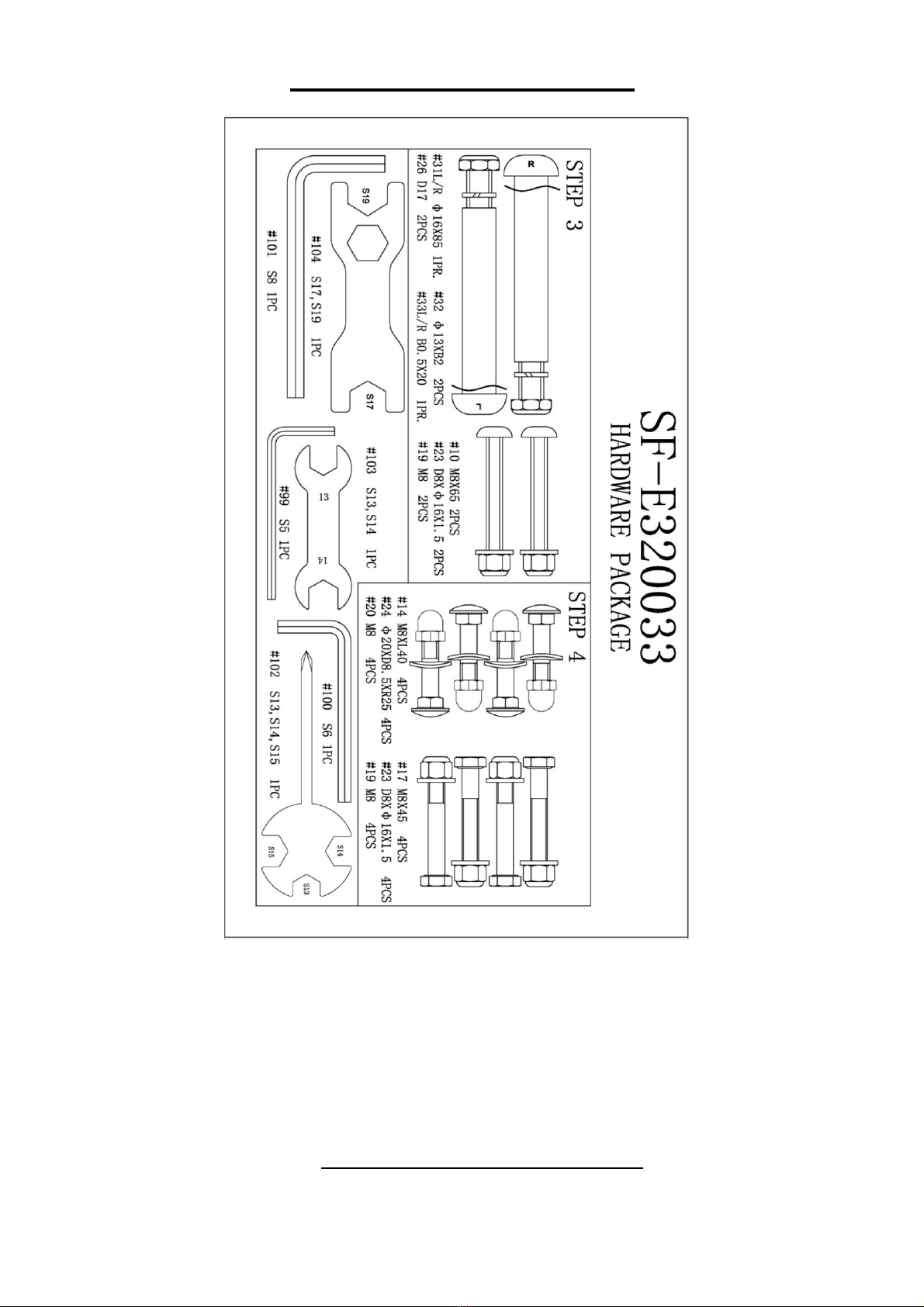
Sunny PERFORMANCE INTERACTIVE Series User manual

1
IMPORTANT SAFETY INFORMATION
We thank you for choosing our product. To ensure your safety and health, please use this
equipment correctly. It is important to read this entire manual before assembling and using the
equipment. Safe and effective use can only be achieved if the equipment is assembled, maintained,
and used properly. It is your responsibility to ensure that all users of the equipment are informed of
all warnings and precautions.
1. Before starting any exercise program, you should consult your physician to determine if you
have any medical or physical conditions that could put your health and safety at risk or prevent
you from using the equipment properly. Your physician’s advice is essential if you are taking
medication that affects your heart rate, blood pressure, or cholesterol level.
2. Be aware of your body’s signals. Incorrect or excessive exercise can damage your health. Stop
exercising if you experience any of the following symptoms: pain, tightness in your chest,
irregular heartbeat, shortness of breath, lightheadedness, dizziness, or feelings of nausea. If
you do experience any of these conditions, you should consult your physician before continuing
with your exercise program.
3. Keep children and pets away from the equipment. The equipment is designed for adult use only.
4. Use the equipment on a solid, flat level surface with a protective cover for your floor or carpet.
To ensure safety, the equipment should have at least 4 feet (120 CM) of free space all around it.
5. Ensure that all nuts and bolts are securely tightened before using the equipment. The safety of
the equipment can only be maintained if it is regularly examined for damage and/or wear and
tear.
6. Always use the equipment as indicated. If you find any defective components while assembling
or checking the equipment, or if you hear any unusual noises coming from the equipment during
exercise, discontinue use of the equipment immediately and do not use until the problem has
been rectified.
7. Wear suitable clothing while using the equipment. Avoid wearing loose clothing that may
become entangled in the equipment.
8. Do not place fingers or objects into the moving parts of the equipment.
9. The maximum weight capacity of this unit is 220 pounds (100 KG).
10.The equipment is not suitable for therapeutic use.
11.To avoid bodily injury and/or damage to the product or property, proper lifting and moving are
required.
12.Your product is intended for use in cool and dry conditions. You should avoid storage in extreme
cold, hot or damp areas as this may lead to corrosion and other related problems.
13.This equipment is designed for indoor and home use only; it is not intended for commercial use.

2
PRE-ASSEMBLY CHECK LIST
.Before you start to assemble, please make sure all parts are included.
No.
Description
Spec.
Qty.
No.
Description
Spec.
Qty.
1
Main Frame
1
34
Meter
1
2
Handlebar Post
1
38
Nut Cap
S13
2
3L/R
Swing Bar
1PR.
39
Nut Cap
S19
2
4
Pedal Support Tube
2
43L/R
Pedal
1PR.
5
Armrest
1
A
Manual
1
6L/R
Handlebar
1PR.
B
Thank You Card
1
8
Front Stabilizer
1
C
Hardware Package
1
9
Rear Stabilizer
1
D
Battery
2
28
Long Axle
1

3
HARDWARE PACKAGE
Ordering Replacement Parts (U.S. and Canadian Customers only)
Please provide the following information in order for us to accurately identify the
part(s) needed:
✓The model number (found on cover of manual)
✓The product name (found on cover of manual)
✓The part number found on the “EXPLODED DIAGRAM” and “PARTS LIST”
(found near the end of the manual)
Please contact us at support@sunnyhealthfitness.com or 1-877-90SUNNY
(877-907-8669).

4
ASSEMBLY INSTRUCTIONS
We value your experience using Sunny Health and Fitness products. For assistance with parts or
(877-907-8669).
STEP 1:
Remove 2 Paper Tubes (No. E), 4 Carriage
Bolts (No. 13), 4 Arc Washers (No. 24) and
4Cap Nuts (No. 20) from the Main Frame
(No. 1).
NOTE: You may discard the Paper Tubes
(No. E) or save them to repackage the item
in the future.
Attach the Front Stabilizer (No. 8) and the
Rear Stabilizer (No. 9) to the Main Frame
(No. 1) with 4 Carriage Bolts (No. 13), 4
Arc Washers (No. 24) and 4 Cap Nuts (No.
20) that were just removed. Tighten and
secure with Spanner (No. 102).

5
We value your experience using Sunny Health and Fitness products. For assistance with parts or
(877-907-8669).
STEP 2:
Remove 4 Screws (No. 12), 4 Spring
Washers (No. 25) and 4 Arc Washers (No.
24) from the Main Frame (No. 1) using Allen
Wrench (No. 100).
NOTE: Make sure the Tension Controller
(No. 50a) is at the lowest level before you
connect the cable. This ensures the wires
are at their longest point. We recommend the
assistance of a second person to help hold
the Handlebar Post (No. 2). This will make
the connection easier when you are
attaching Tension Hook (No. 53)to the
Tension Cable (No. 50b).
Attach the Tension Cable (No. 50b) into the
metal bracket of Tension Hook (No. 53) as
shown in drawing A-①. Then, pull Tension
Cable (No. 50b) upward and insert it into the
slot of metal bracket of Tension Hook (No.
53) as shown in drawing A-③. Make sure the
metal fitting on Tension Cable (No. 50b) is
secured in the metal bracket.
Connect the Sensor Extension Wire 1 (No.
52)to the Sensor Extension Wire 2 (No.
51).
Attach the Handlebar Post (No. 2) to the
Main Frame (No. 1) with 4 Screws (No. 12),
4 Spring Washers (No. 25) and 4 Arc
Washers (No. 24) that were just removed.
Tighten and secure with the Allen Wrench
(No. 100).
NOTE: Do not cut or pinch any wires when
attaching the Handlebar Post (No. 2).

6
We value your experience using Sunny Health and Fitness products. For assistance with parts or
(877-907-8669).
STEP 3:
Remove 2 Hex Screws (No. 16),2Spring
Washers (No. 25), 2Flat Washers (No. 22)and 2
Wave Washers (No. 27)from the Long Axle (No.
28) by using Spanner (No. 102) and Spanner
(No. 103).
Insert the Long Axle (No. 28)into the Handlebar
Post (No. 2), then insert 2 Wave Washers (No.
27)that were just removed into the both sides of
Long Axle (No. 28). Attach the 2 Swing Bars (No.
3L/R) to both sides of the Long Axle (No. 28)
using 2Flat Washers (No. 22), 2 Spring
Washers (No. 25)and 2 Hex Screws (No. 16)
that were just removed. Pre-secure with Spanner
(No. 102) and Spanner (No. 103).
NOTE: Do not completely tighten the Hex Screws
(No. 16)yet.
Attach 1 Pedal Support Tube (No. 4) to the left
side of the Crank (No. 29)with 1 Left Hinge Bolt
(No. 31L) and 1 Wave Washer (No. 26). Turn the
Left Hinge Bolt (No. 31L) counter-clockwise with
your hand. Then attach 1 Spring Washer (No. 32)
and 1 BLACK color Left Nylon Nut (No. 33L) to
the end of Left Hinge Bolt (No. 31L) and turn the
Left Nylon Nut (No. 33L) clockwise.
Attach 1 Pedal Support Tube (No. 4) to the right
side of the Crank (No. 29)with 1 Right Hinge
Bolt (No. 31R) and 1 Wave Washer (No. 26). Turn
the Right Hinge Bolt (No. 31R) clockwise with
you hand. Then attach 1 Spring Washer (No. 32)
and 1 WHITE color Right Nylon Nut (No. 33R) to
the end of Right Hinge Bolt (No. 31R) and turn
the Right Nylon Nut (No. 33R) counter-clockwise.
NOTE: Please do not fully tighten at this time.
The Left Hinge Bolt (No. 31L) is labeled “L”, while
the Right Hinge Bolt (No. 31R) is labeled “R”.
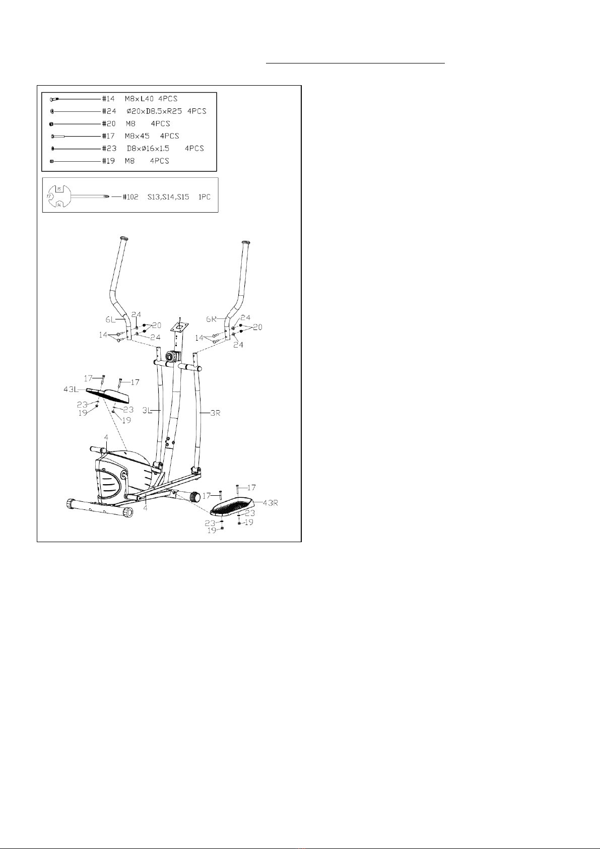
Attach 2 Swing Bars (No. 3L/R) to 2 Pedal
Support Tubes (No. 4) with 2 Bolts (No. 10),2
Flat Washers (No. 23) and 2 Nylon Nuts (No. 19)
using Allen Wrench (No. 99) and Spanner (No.
102).
Note: Please do not fully tighten at this time.
Firstly, fasten 2 Nylon Nuts (No. 33L/R) and 2
Hinge Bolts (No. 31L/R) using Allen Wrench
(No. 101) and Spanner (No. 104).
Secondly, fasten 2 Bolts (No. 10) and 2 Nylon
Nuts (No. 19)using Allen Wrench (No. 99) and
Spanner (No. 102).
Then fasten 2 Hex Screws (No. 16)using
Spanner (No. 102) and Spanner (No. 103).
Finally, cover 2 Nut Caps (No. 38) and 2 Nut
Caps (No. 39).
NOTE: Ensure that all bolts and washers are in
place and partially threaded in before completely
tightening any of them.

7
We value your experience using Sunny Health and Fitness products. For assistance with parts or
(877-907-8669).
STEP 4:
Attach 2 Handlebars (No. 6L/R) on the 2
Swing Bars (No. 3L/R) with 4 Carriage
Bolts (No. 14), 4 Arc Washers (No. 24)and
4 Cap Nuts (No. 20)using Spanner (No.
102).
Attach the 2 Pedals (No. 43L/R) to the 2
Pedal Support Tubes (No. 4) using 4 Hex
Bolts (No. 17), 4 Flat Washers (No. 23)and
4 Nylon Nuts (No. 19). Tighten and secure
with Spanner (No. 102).

8
We value your experience using Sunny Health and Fitness products. For assistance with parts or
(877-907-8669).
STEP 5:
Remove 2 Screws (No. 12), 2 Spring
Washers (No. 25)and 2 Arc Washers (No.
24) from the Handlebar Post (No. 2) using
Allen Wrench (No. 100).
Attach the Armrest (No. 5) to the Handlebar
Post (No. 2) in place. Secure it with 2
Screws (No. 12), 2 Spring Washers (No.
25)and 2 Arc Washers (No. 24)using Allen
Wrench (No. 100).
NOTE: If the Left & Right Handlebars (No.
6L & No. 6R) rubs against the Armrest (No.
5) during the workout please recheck if the
Left & Right Handlebars (No. 6L & No. 6R)
are assembled to Left & Right Swing Bars
(No. 3L & No. 3R) according to the label
marked with L or R.
STEP 6:
Remove 4 Screws (No. 59) from the Meter
(No. 34) with Spanner (No. 102).
Connect the Sensor Extension Wire 2 (No.
51) to the wire from the Meter (No. 34).
Attach the Meter (No. 34)to the bracket of
the Handlebar Post (No. 2) by using 4
Screws (No. 59) that were just removed
with Spanner (No. 102). Then plug the
Pulse Wire (No. 55) to the jack on the back
of the Meter (No. 34).
NOTE: To avoid damaging the wires, please
push them into the Handlebar Post (No. 2)
before secure the Meter (No. 34)onto the
bracket.
The assembly is complete!

9
ADJUSTMENT GUIDE
ADJUSTING THE BALANCE
In order to achieve a smooth and comfortable ride,
you must ensure that the elliptical is stabled and
secured. If you notice that the elliptical is unbalanced
during use, you should adjust the Rear End Caps
(No. 41)located on the rear stabilizer until the
elliptical becomes levelled with the floor surface.
ADJUSTING THE TENSION
Adjust the tension by rotating the Tension
Controller (No. 50a) clockwise to increase the level
of resistance. Rotate the Tension Controller (No.
50a) counter-clockwise to decrease the level of
resistance.
Tension levels are set at Level 1 being the lowest
and Level 8 being the highest.
MOVING THE ELLIPTICAL
There are Transportation Wheels (No. 42) located
on the Front Stabilizer (No. 8). Hold the Armrest
(No. 5) on the Handlebar Post (No. 2) and press
down the front of the elliptical until the
Transportation Wheels (No. 42) touch the ground.
Now you can move the elliptical.

10
BATTERY INSTALLATION & REPLACEMENT
BATTERY INSTALLATION
1. Take out 2 AAA batteries from computer box.
2. Press the buckle of battery cover on the Meter (No. 34), then remove battery cover.
3. Install 2 AAA batteries into the battery case on the back of the Meter (No. 34). Pay attention to
the battery + and –poles before installing.
4. Press the buckle of battery cover, then put the battery cover back to the back of the Meter (No.
34).
The installation is complete!
BATTERY REPLACEMENT
1. Press the buckle of battery cover on the back of the Meter (No. 34), then remove battery cover.
2. Remove the 2 old AAA batteries in the battery case and install 2 new AAA batteries into the
battery case on the back of the Meter (No. 34). Pay attention to the battery + and –poles before
installing.
3. Press the buckle of battery cover, then put the battery cover back to the back of the Meter (No.
34).
The replacement is complete!
BATTERY DISPOSAL
Dispose the batteries according to the laws and regulations of your local region. Some batteries
may be recycled. When disposing or recycling, do not mix battery types.
Battery
Cover
Battery
34

11
EXERCISE METER
FUNCTION BUTTONS:
MODE: Press the button to select TIME, DISTANCE, and
CALORIES to preset.
Press the button for selection function display value on
LCD or enter after setting.
Press the button and hold for 3 seconds to reset all values
except odometer to zero.
(When user replaces the batteries, all the values will reset
to ZERO automatically).
SET: To set up the target value of TIME, DISTANCE, and
CALORIES.
Press the button and hold for 2 seconds to speed up the
increment.
RESET: Press the button to reset function value when setting.
Press the button and hold for 3 seconds to reset all values
except odometer to zero (When the user replaces batteries,
all the values will reset to ZERO automatically).
FUNCTIONS & OPERATIONS:
1. BATTERY INSTALLATION:
Please install 2 AAA1.5V batteries in the battery case on the back of meter. (Whenever batteries
are removed, all the function values will be reset to zero.)
2. AUTO ON/OFF:
Once the user begins to exercise, the meter will show the workout value automatically. After
about 4 minutes of inactivity, the meter will turn off. Odometer value does not reset to 0 when the
meter turns off. When the user starts to exercise again, the workout value of odometer will
accumulate continuously.
3. AUTO SCAN:
After the meter is powered on, press MODE button and the LCD will display all function values
from TIME-SPEED-DISTANCE-CALORIES-ODOMETER-PULSE. Each value will be held for 6
seconds.
4. SPEED:
Displays the current training speed from 0.0 to 99.9 MPH (Miles per hour).
5. DISTANCE:
Accumulates total distance from 0.00 up to 9999 M (Miles).
The user may preset target distance by pressing the SET & MODE buttons. Each increment is
0.1 M (Miles) and will automatically count down from target value during exercise.
6. TIME:
Accumulates total time from 00:00 up to 99:59.
The user may preset target time by pressing SET & MODE buttons. Each increment is 1 minute
and will automatically counts down from target value during exercise.

12
7. CALORIES:
Accumulates calories burned during training from 0.0 to 9999 (Cal). The user may also preset
the target calories before training by pressing the SET & MODE buttons. Each setting increment
is 1 Cal and will automatically counts down from target value during exercise.
NOTE: This data is a rough guide which cannot be used in medical treatment.
8. ODOMETER:
Displays the total accumulated distance from 0.0 to 9999 M (Miles). User can also press MODE
button to display the odometer value.
9. PULSE:
The meter will display the user's heart rate in beats per minute (BPM) during training.
NOTE: This data is a rough guide which cannot be used in medical treatment.
10. RESET:
Press the button and hold for 3 seconds to reset all values except odometer to zero.
NOTE:
1. If the meter display is abnormal, please re-install the new batteries and try again. Always change
both batteries at the same time. Do not mix battery types and do not mix old and new batteries.
2. Battery Spec: 1.5V UM-4 or AAA (2PCS).
3. Dispose the batteries safely, according to your state and regional guidelines.
APP CONNECTION:
1. Scan the QR code below to download the SunnyFit app onto your mobile device.
2. If this is your first time using the SunnyFit app, follow the in-app instructions to register for your
free SunnyFit account and log in.
3. Ensure that the Bluetooth function is turned on from your mobile device.
4. To connect the equipment to the SunnyFit app:
a. From the “Workout” tab, press on the “Search” button to search for your equipment.
b. Once your equipment appears on the list, tap the “Select” button to confirm.
c. NOTE: If your equipment does not appear on the "Searching for Equipment" list, check the
EXERCISE METER on your equipment to ensure that it is not in sleep mode and your
phone's Bluetooth function is on, then tap "Retry" to search again.
d. Once your equipment shows up on the “Workout” tab as “Currently Selected”, your
equipment is now ready to display, track, and record your equipment’s workout stats on the
app!
5. If you are unable to replicate these steps, or have any other issues with the SunnyFit app,
to request support (“Me” tab -> “Contact Us”).

13
EXPLODED DIAGRAM 1
EXPLODED DIAGRAM 2

14
PARTS LIST
No.
Description
Spec.
Qty.
No.
Description
Spec.
Qty.
1
Main Frame
1
50a
Tension Controller
1
2
Handlebar Post
1
50b
Tension Cable
1
3L/R
Swing Bar
1PR.
51
Sensor Extension Wire 2
1
4
Pedal Support Tube
2
52
Sensor Extension Wire 1
1
5
Armrest
1
53
Tension Hook
1
6L/R
Handlebar
1PR.
54
Wire Plug
1
7
U Bracket
2
55
Pulse Wire
1
8
Front Stabilizer
1
56
Pulse Sensor
2
9
Rear Stabilizer
1
57
Arc Washer
1
10
Bolt
M8×65
2
58
Screw
M5×50
1
11
Screw
M8×38×L12
2
59
Screw
M5×10
4
12
Screw
M8×16
6
60
Screw
ST4.2×18
15
13
Carriage Bolt
M8×65
4
61
Plug
2
14
Carriage Bolt
M8×L40
4
62
Screw
M6×8
2
15
Hex Bolt
M10×45
2
63
Screw
M6×12
6
16
Hex Screw
M8×20
2
64
Flywheel Axle
1
17
Hex Bolt
M8×45
4
65
Flat Washer
D6×Φ12×1.2
2
18
Nylon Nut
M10
2
66
Flat Washer
D10×Φ14×1
1
19
Nylon Nut
M8
9
67
Flat Washer
D6×Φ16×1.5
3
20
Cap Nut
M8
8
68
Square Magnet
4
21
Flat Washer
D10×Φ26×2
4
69
Magnetic Board
1
22
Flat Washer
D8.2×Φ32×2
2
70
Magnetic Board Axle
1
23
Flat Washer
D8×Φ16×1.5
8
71
Axle Spring Washer
D12
2
24
Arc Washer
Φ20×D8.5×R25
14
72
Spring
Φ1.6×Φ15×L47.2
1
25
Spring Washer
D8
8
73
Screw
Φ14×Φ10×M8×20.5
1
26
Wave Washer
D17
2
74
Hex Screw
M6×15
3
27
Wave Washer
D20
2
75
Belt
350PJ6
1
28
Long Axle
1
76
Tension Extension Wire
1
29
Crank
1
77
Nut
2
30
Spacer
Φ14×49
2
78
Washer
1
31L/R
Hinge Bolt
Φ16×85
1PR.
79
Locking Nut-L
1
32
Spring Washer
Φ13×B2
2
80
Open Face Bearing
2
33L/R
Nylon Nut
B0.5×20
1PR.
81
Bearing Housing
2
34
Meter
1
82
Locking Nut-R
1
35
Plastic Bushing
Φ32×Φ14.1×19.5
4
83
Big Flat Washer
1
36
Plastic Bushing
Φ24×16×Φ16.1
4
84
Flywheel
1
37
Plastic Bushing
Φ26.8×28
6
85
Bearing
6001-2RS
4
38
Nut Cap
S13
2
86
Wave Washer
D12
2
39
Nut Cap
S19
2
87
Fixed Plate
2
40
Front End Cap
2
88
Bearing Bracket
2
41
Rear End Cap
2
89
Spring Washer
D6
5
42
Transportation Wheel
2
90
Spring
Φ18×Φ3×L58.5
1
43L/R
Pedal
1PR.
91
Hex Bolt
M5×60
1
44
Mushroom Cap
2
92
Hex Nut
M5
2
45
Round Cap
2
93
Idler Wheel
1
46
Square Cap
80×40×1.5
1
94
Idler Wheel Linkage
1
47
Square Cap
40x25x1.5
2
95
Sensor Bracket
1
48
Foam Grip
Φ27×T3×480
2
96
Belt Pulley
1
49
Foam Grip
Φ24×Φ30×390
2
97L/R
Belt Cover
1PR.

15
No.
Description
Spec.
Qty.
No.
Description
Spec.
Qty.
98
Crank Cover
2
103
Spanner
S13,S14
1
99
Allen Wrench
S5
1
104
Spanner
S17,S19
1
100
Allen Wrench
S6
1
105
Nylon Nut
M6
1
101
Allen Wrench
S8
1
106
Adjustable Belt Bolt
M6x36
1
102
Spanner
S13,S14,S15
1
107
Sensor Wire
1
Version 1.0

16
This manual suits for next models
1
Table of contents
Other Sunny Fitness Equipment manuals

Sunny
Sunny SF-E2310 User manual

Sunny
Sunny SF-E1405 User manual

Sunny
Sunny Y.08 User manual

Sunny
Sunny ESSENTIAL Series User manual

Sunny
Sunny SF-RW5623 User manual

Sunny
Sunny SF-B1110S User manual

Sunny
Sunny SF-B2640 User manual

Sunny
Sunny SF-807 User manual

Sunny
Sunny TreadPad SF-T7970 User manual

Sunny
Sunny SF-E3416H User manual

Sunny
Sunny ROW-N-RIDE PLUS User manual

Sunny
Sunny SF-E3608 User manual

Sunny
Sunny SF-RW5727 User manual

Sunny
Sunny SF-VP822057 User manual

Sunny
Sunny SF-RW1406 User manual

Sunny
Sunny SF-RW5508 User manual

Sunny
Sunny SF-E320048 User manual

Sunny
Sunny SF-XF9925 User manual

Sunny
Sunny SF-B1423 User manual

Sunny
Sunny SF-BH6920 User manual