manuals.online logo
Brands
  1. Home
  2. •
  3. Brands
  4. •
  5. Surveon
  6. •
  7. DVR
  8. •
  9. Surveon SMR Series User manual

Surveon SMR Series User manual

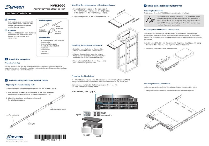
QUICK INSTALLATION GUIDE
Installation
© by Surveon Tech no lo gy, I nc . All r ig ht s re se rv ed .
Password:
Only qualified service personnel should install and service this product in order to avoid risk of injury from
electrical shock and energy hazard.
Observe all ESD (Electro-static Discharge) procedures during installation to avoid damage to the recorder
and its components.
Warning!
QM0 0 S MR A D R 1 1
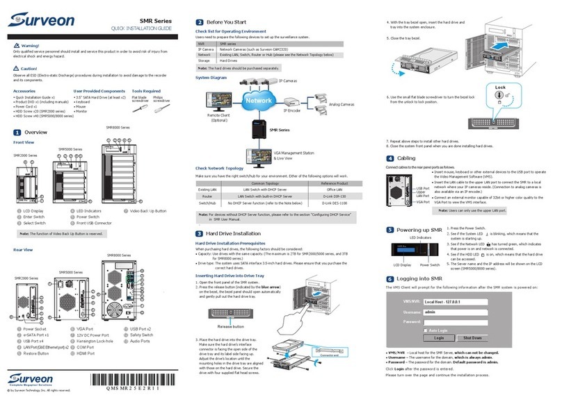
Rear View
Adding Hard Drives
2
Hard Drive Installation Prerequisites
Pu rcha se hard d rive s having the sa me capacity a nd using same i nterface wi th the pre-in stall ed ones .
Inserting Hard Drive into Drive Tray
1. O pen the front panel of the EMR s ystem .
2. P ress the rele ase button (i ndicated by t he blu e arro w)
on t he bezel, the b ezel panel sh ould open automati cally
an d gently pull o ut the ha rd dri ve tray.
3. P lace the hard d rive i nto the d rive t ray.
Ma ke sur e the hard drive’s inter face
co nnector is th e open si de of the drive
tray an d its lab el side facing up. Adjust
th e drive’s l ocation unt il the mo unting
ho les in the drive tray are aligned w ith
th ose on the hard d rive . Secure the drive
wi th fou r suppl ied flat head s crews.
Smart Megapixel Recorder
Desktop Series
Note: For users of 6 ba y models, ple ase go to C apture Card Q uick Instal latio n Guide first .
4. With th e tray bezel open, insert t he hard drive and
tray in to the system enclos ure.
5. C lose the tra y beze l.
6. U se the small flat blad e screw drive r to turn the bez el lock
from the u nlock to lock p ositi on.
7. Repea t abov e steps to inst all oth er hard drives.
8. C lose the syst em front pane l when you are do ne installing
ha rd dri ves.
. . . . . .
/4
1/3
User-provide Items
●
●
US B compatibl e Keyboard a nd Mouse
LAN Cab le
●
●
●
Mo nitor
3. 5" SATA Hard Drive
(O ptional) PC (s) wit h Windows XP (or above) Used a s Remote
VM S Client Mana gemen t Center
Flat blade
Screwdriver
Philips
Screwdriver
● ●
● Quick Installation Guide x1
● Product DVD x1 (including manuals)
● Power Cord x1
● HDD Screw x20
● LAN Cable
● China RoHS x1
Accessories for 2 Bay Models
● Quick Installation Guide x1
● Product DVD x1 (including manuals)
● Power Cord x1
● HDD Screw x40
● LAN Cable
● China RoHS x1
Accessories for 5 Bay Models
● Quick Installation Guide x1
● Product DVD x1 (including manuals)
● Power Cord x1
● HDD Screw x40
● Capture Card and BNC Cables
● LAN Cable
● China RoHS x1
Accessories for 6 Bay Models
● Quick Installation Guide x1
● Product DVD x1 (including manuals)
● Power Cord x1
● HDD Screw x40
● LAN Cable
● China RoHS x1
Accessories for 8 Bay Models
Front View
Hardware Overview
1
1LCD Display
2Enter Switch
3Select Switch
LED Indicators
Power Switch
4
5
6
7
Front USB Connector
Video Switch
2 bay models
4 5
6
5 bay models
1 2 3 4 5
6
8 bay models
1 2 3 4 5
6
7
6 bay models
1 2 3 4 5
6
Power Socket
e-SATA Port x1
USB Port x4
HDMI Port
LAN Port x2
Restore Button
USB Port x2
Safety Switch
Audio Ports
VGA Port
Kensington Lock-hole
COM Port
12V DC Power Port
5
6
7
8
9
10
11
12
7
2 bay models
2
3
4
5
6
8
5 bay models
2
3
4
5
6
8
1
6 bay models
9
3
4
1
5
6
9
10
11
12
13
8
14
1
2
3
4
5
6
7
8
13
14 BNC Connector
Note: The functions of e-SATA port and COM port are reserved.
9
8 bay models
Mo del
2 bay mod els
5 bay mod els
6 bay mod els
Space f or Hard Dri ves RAID Op tion s
2 HD D
5 HD D
6 HD D
No nRAID, R AID1
No nRAID, R AID1 ,5
No nRAID, R AID1 , 5
. .
8 bay mod els 8 HD D No nRAID, R AID1 , 5
System Connections
3
●
● Insert the LAN Cable to the LAN Port to a local network where your IP Camera reside.
(Connection to analog cameras is also available via an IP encoder).
● Connect an external monitor capable of 32 bit or higher color quality to the VGA port to view the
VMS interface.
Insert mouse, keyboard to the USB for operating VMS on the SMR system.
Co nnect cable s to the rear panel port s as fol lows:
Check Network Topology
Pl ease make sure if you r netwo rk env ironment ha s DHCP se rvice. For d evices without DHC P server
functi on such as switch and hu b, ple ase choose Fi xed IP Address in Install Wizar d (s st ep7)
an d then enable D HCP ser ver after log ging into VMS (secti on 7).
ec tion 6,
Remote Client/Web Client
Management Center
VGA Station for Local Client
Internet
SELECT
ENTER
SMR Pr o
DHCP Router
GbE Switch
Smart Megapixel Video Recorder
Camera(s)
Wh en you r un the SM R series for the first time, you nee d to go through the following steps w ithin t he
Qu ick In stall W izard after l oggin g in.
1. Make s ure the hard dr ives a re inserted into the S MR case . Click Next to conti nue.
2. C lick Storage Man ager t o do RAID confi gura tion.
Logging into SMR
5
Th e VMS Client wi ll prom pt for t he fol lowin g info rmati on after the SM R syste m is powe red on :
●
●
VMS/NVR: The default IP address for the SMR Server, which is the local host.
●
Username: The username of the domain, which is always admin.
●
Password: The password of the domain. Default password is admin.
●
Access Method: Directly Access.
Type: Choose VMS.
Cl ick Login aft er the pa ssword is ent ered.
Access Method:
Port:
Type:
VMS/NVR:
Username:
Password:
CancelLogin
Auto Login
admin
admin
Local Host - 127.0.0.1
VMS
Directly Access
Search
Install Wizard
6
Note: (1) Auto Login is reco mmend ed to be ticked. (2) If you need to conn ect remote PC (s)
to t he SMR server w ithin a private LAN, ple ase refer to Port Forwa rdi ng an d Star t the V MS Client
se ction in SMR us er manu al for m ore details .
Cl ick Settin g, choose the R AID level in th e Adv anced Sett ings dia logue , and then clic k Crea te Log ical
Drive to creat e the RAI D configuration .
Pl ease click OK a fter th e configuration i s done, and the s ystem w ill reboot au tomat icall y.
Ab out 2 minutes l ater, th e Wizard window will a ppear a gain. Click N ext to c ontin ue.
Note: (1) If you r monitor res oluti on is lower tha n 1280x 1024, a warn ing mes sage wi ll jump out aft er SMR
st arts up. You can c hange the res olution setting at this ti me. The n you ca n skip step 4 lat er.
3. Syste m initializ ation w ill sta rt.
Th e system will shut dow n after t he initializatio n is done s ucce ssfully. Pl ease click OK .
Press the power s witch t o restart the s ystem . About 1.5 min utes la ter, the W izard windo w will po p up again.
4. Click O pen Resolution Tool to chang e the resolut ion setting .
Ch oose Single Disp lay as t he operate mo de and monito r as the di splay selec tion in Primary De vice .
Ch ange the scre en resoluti on in Dis play S ettings. Cl ick OK to finis h.
Cl ick Next to continu e.
5. T he default password for S MR logi n is admin. If yo u want t o change the pa sswor d, please ent er a new
on e in both the bla nks of New Passwor d and Confir m.
/4
Note: SMR6/8 bay models support du al disp lay.
Note: SMR8000 serie s will no t go through st ep 3.
Powering up
4
.
/4
2/3
2 Bay Models
1. Attach the po wer cab le to the power socket on the re ar pane l.
2.
3. S ee if the s ystem LED is bl inkin g, which mean s that th e system
is s tarting up.
4. See if th e netwo rk LED has turn ed green, which indi cates that
th e power is on and n etwor k is connecte d.
5. S ee if the H DD LED is on, whi ch means that the hard drive c an
be a cces sed.
Press the power s witch .
LED Indicators
Power Switch
LED Indicators
LCD Display Power Switch
1. Attach the po wer cab le to the power socket on the re ar panel.
2.
3. S ee if the s ystem LED is bl inkin g, which mean s that th e system
is s tarting up.
4. See if th e netwo rk LED has turn ed green, which indi cates that
th e power is on and n etwor k is connecte d.
5. S ee if the H DD LED is on, whi ch means that the hard drive c an
be a cces sed.
6. T he Server nam e and the IP address wil l be show n on the LCD screen.
Press the power s witch .
5 Bay Models
LED Indicators
LCD Display Power Switch
1. Attach the po wer cab le to the power socket on the re ar pane l.
2. M ake su re the safety switc h on the rear pan el is swi tched to the “- ”
si de, which mea ns that i t is turned on.
3.
4. See if th e syste m LED is blinki ng, whi ch means that t he syst em
is s tarting up.
5. S ee if the n etwork LED ha s turne d gree n, whic h indicates t hat
th e power is on and n etwor k is connecte d.
6. S ee if the H DD LED is on, whi ch means that the hard drive c an
be a cces sed.
7. The Server name and the I P address wil l be show n on the LCD screen.
Press the power s witch .
6 Bay Models
LED Indicators
LCD Display Power Switch
1. Attach the po wer cab le to the power socket on the re ar pane l.
2. M ake su re the safety switc h on the rear pan el is swi tched to the “- ”
si de, which mea ns that i t is turned on.
3.
4. See if th e syste m LED is blinki ng, whi ch means that t he syst em
is s tarting up.
5. S ee if the n etwork LED ha s turne d gree n, whic h indicates t hat
th e power is on and n etwor k is connecte d.
6. S ee if the H DD LED is on, whi ch means that the hard drive c an
be a cces sed.
7. The Server name and the I P address wil l be show n on the LCD screen.
Press the power s witch .
8 Bay Models
/4
3/3
Th e IP wil l change afte r the sy stem is resta rted . Click Next t o cont inue.
8. C lick S can for Cameras t o add ca meras to the S MR ser ver.
Th e came ras that can b e adde d to the server will be d ispl ayed .
To add a ca mera to the se rver, check the box b y the camera e ntry. You may a lso ch eck the Sele ct All box
at t he bottom of t he win dow to select a ll the c ameras found.
En ter th e username an d pass word, and press Apply Se lected. C lick Ok to add the sele cted c ameras to
th e serv er.
9. C lick F inish to end the wiz ard.
10 . The VM S will automa tica lly start aft er the w izard is finished . Please refer to SMR user manual for more
de tail s.
7. Set an IP addres s for the SMR se rver. Please check i f your n etwo rk env iron ment has DHCP s ervice firs t.
If n ot, pl ease choose Fixed IP Add ress.
6. C hoos e the time zone and set t he act ual date and time for the SMR syste m.
Note: You m ust set the rig ht time zone for the SMR syste m, or yo u canno t access the re mote record ing.
Server Settings
Scan For Cameras
Add Cameras
Schedule Manager
Logout
Alarm Rule Settings
View Log
Digital I/O Settings
Configurations Rename
About
DHCP Server
IP Address Ranage
Subnet Ma sk
Router
DNS
DHCP Set tings
DHCP Set tings
192 . 16 8 . 22 . 2
255 . . . 0255 25 5
192 . . . 10 0168 22
192 . . . 1168 22
192 . 168 . 2 2 . 20
Enab le D is ab le
Live View Playback
Th e DHCP functi onality sho uld be turned o n when there is n o DHCP se rvice avai lable. When e nable d, the VMS
wi ll assu me DHCP S erve r dutie s and assign ad dresses within the range s pecif ied.
Enabling DHCP Server (Optional)
7
3. T ick Enable a nd then click OK to star t the service .
●
1. R ight-cli ck the VM S Server and se lect Configura tion s > DHCP Server opti on to bri ng up the DHCP Se rver
di alog box.
2. F ill in the foll owing infor mation:
IP Address Range - The rang e of addresses to be ass igned . The first IP ad dress s hould be lowe r than th e
se cond IP addre ss.
● Subnet Mask
●
●
Router - The rou ter IP
Domain Name - The DNS IP

Other manuals for SMR Series

2

Other Surveon DVR manuals

Surveon SMR Series Use and care manual

Surveon

Surveon SMR Series Use and care manual

Surveon SMR2000 Series Use and care manual

Surveon

Surveon SMR2000 Series Use and care manual

Surveon EMR2000 User manual

Surveon

Surveon EMR2000 User manual

Surveon NVR5316 User manual

Surveon

Surveon NVR5316 User manual

Surveon NVR2000 Series User manual

Surveon

Surveon NVR2000 Series User manual

Surveon SMR8040U User manual

Surveon

Surveon SMR8040U User manual

Surveon SMR5016 User manual

Surveon

Surveon SMR5016 User manual

Surveon SMR2000 Series User manual

Surveon

Surveon SMR2000 Series User manual

Surveon SMR5000 Series User manual

Surveon

Surveon SMR5000 Series User manual

Surveon NVR2100 Series User manual

Surveon

Surveon NVR2100 Series User manual

Popular DVR manuals by other brands

COP Security 15-DVR16SAE-LAN user manual

COP Security

COP Security 15-DVR16SAE-LAN user manual

IVS S9353 installation guide

IVS

IVS S9353 installation guide

Swann ADVANCED-SERIES H.264 user manual

Swann

Swann ADVANCED-SERIES H.264 user manual

LJD Digital Security Leviathan Series user guide

LJD Digital Security

LJD Digital Security Leviathan Series user guide

WATASHI DH-DVR0404 user manual

WATASHI

WATASHI DH-DVR0404 user manual

ACTi ZNR user manual

ACTi

ACTi ZNR user manual

Sanyo DSR-2004 instruction manual

Sanyo

Sanyo DSR-2004 instruction manual

urmet domus PRO 1098 user manual

urmet domus

urmet domus PRO 1098 user manual

EverFocus 920 instruction manual

EverFocus

EverFocus 920 instruction manual

Panasonic WJ-ND400K/G operating instructions

Panasonic

Panasonic WJ-ND400K/G operating instructions

Weldex WDR-8264-2TB Quick manual

Weldex

Weldex WDR-8264-2TB Quick manual

TeleEye JN6400 user manual

TeleEye

TeleEye JN6400 user manual

Vantech VP-454CVI user manual

Vantech

Vantech VP-454CVI user manual

Samsung SDE-4001 user manual

Samsung

Samsung SDE-4001 user manual

WebGate MD1600L eDVR user guide

WebGate

WebGate MD1600L eDVR user guide

JVC VR-609U - 9 Channel Digital Video Recorder instructions

JVC

JVC VR-609U - 9 Channel Digital Video Recorder instructions

Ganz Digimaster DR4N-Lite instruction manual

Ganz

Ganz Digimaster DR4N-Lite instruction manual

XtendLan DVR-470BFV user guide

XtendLan

XtendLan DVR-470BFV user guide

manuals.online logo
manuals.online logoBrands
  • About & Mission
  • Contact us
  • Privacy Policy
  • Terms and Conditions

Copyright 2025 Manuals.Online. All Rights Reserved.