Swegon CASA W4 Smart Manual

W4_c_EN-t
Swegon Home Solutions
CASA®W4 Smart
Installation, commissioning and maintenance instruction

W4.311016
Swegon reserves the right to alter specifications.www.swegonhomesolutions.com
Installation, operation and maintenance instructions
for design engineers, installation engineers and service personnel
Contents
2
Important information ............................................. 3
1. General description............................................... 4
1.1 Enclosure .........................................................................4
1.2 Fans.................................................................................4
1.3 Filter ................................................................................4
1.4 Heat exchanger................................................................4
1.5 Temperature ....................................................................4
1.6 Protective safety functions ...............................................5
2. Installation............................................................. 6
2.1 Ventilation unit’s installation site ......................................6
2.1.1 Wall mounting..............................................................6
2.1.2 Ceiling mounting..........................................................6
2.2 Condensate discharge......................................................7
2.3 Ducts...............................................................................8
2.4 Sealing around duct penetration collars ...........................8
2.5 Electric and control cables................................................8
2.6 Bypass for kitchen............................................................9
2.7 Installation of the Smart control panel............................10
2.8 To connect water pipes in the Econo model ...................10
3. Commissioning.................................................... 11
3.1 To set the airflows..........................................................11
3.1.1 Setting the fan speeds ................................................11
3.2 Smart functions .............................................................11
3.2.1 Selection of Smart functions .......................................12
3.2.2 Automatic Home/Away/Boost system..........................12
3.2.3 Automatic humidity system.........................................12
3.2.4 Automatic air quality system .......................................12
3.2.5 Cooker hood function.................................................12
3.3 Sensor ...........................................................................13
3.4 Control functions with optional items of equipment ......13
3.5 Remote supervision (DDC)..............................................13
3.6 Damper motors..............................................................13
3.7 Re-heater (not Econo) ....................................................13
3.8 Anti-freeze protection....................................................13
3.9 Restoring factory settings...............................................13
3.10 To change the service code ..........................................14
3.11 Use..............................................................................14
4. Service.................................................................. 14
4.1 Service reminder ............................................................14
4.2 To open the ventilation unit ...........................................14
4.3 Filters.............................................................................14
4.4 Heat exchanger..............................................................14
4.5 Fans...............................................................................14
4.6 Other servicing...............................................................15
5. Alarms and troubleshooting.............................. 16
5.1 Alarms...........................................................................16
5.2 Troubleshooting.............................................................16
6. List of components ............................................. 18
7. Technical data...................................................... 19
7.1 Fan capacities (EN 13141-4)...........................................19
7.1.1 W4 .............................................................................19
7.1.2 W4 Econo...................................................................19
7.2 Outputs of the components...........................................20
7.3 Acoustic data.................................................................20
7.4 Econo, pressure loss in water-heated air heaters.............22
7.5 Econo, sizing of the water-heated air heater ..................22
7.6 Electrical wiring diagram................................................23
7.6.1 W4 .............................................................................23
7.6.2 Control functions with accessories ..............................24
7.6.3 Supervision (DDC).......................................................25
7.7 Control diagram ............................................................26
7.7.1 W4 .............................................................................26
7.7.2 W4 Econo...................................................................27
7.8 Dimensions....................................................................28
7.9 Weights .........................................................................28
7.10 Ventilation unit codes ..................................................29
7.11 Accessories for installation ...........................................29
8. Commissioning form........................................... 30
Warranty conditions ............................................... 31
EC Declaration of Conformity ................................ 32

W4.311016
Swegon reserves the right to alter specifications.
3
www.swegonhomesolutions.com
Important information
Qualified personnel only
Only qualified personnel should carry out in-
stallation, configuration and commissioning.
Standards and requirements
The pertinent national standards and regula-
tions dealing with installation, configuration
and commissioning must be followed if the
equipment is to operate correctly.
At the www.swegonhomesolutions.com ad-
dress (Toolbox > Find PDF) you will find the
document “Project planning instructions for
ventilation”, in which power supply, sound,
airflows and duct system requirements are
presented.
Measurement and electrical work
If you carry out voltage tests, measure the
electrical insulation resistance at various
points or perform other remedial meas-
ures that could damage sensitive electronic
equipment, you must first isolate the ventila-
tion unit from the electrical supply grid.
Surge protection
Swegon recommends that all ventilation units
equipped with Smart automatic control be
equipped with a surge protection device.
Earth fault circuit breaker
It is not certain that an earth fault circuit
breaker will operate faultlessly in combi-
nation with the ventilation unit, since the
unit's regulation and control equipment can
cause leakage currents. Comply with local
electrical safety regulations when you install
electrical equipment.
To open the ventilation unit for service
Always ensure that the ventilation unit’s
power supply has been isolated before you
open the inspection door! Wait a few min-
utes before you open the inspection door
on the ventilation unit so that the fans have
time to stop and air heaters, if fitted, have
time to cool down.
There are no components inside the electri-
cal equipment cabinet that can be serviced
by the user. Leave the servicing or these
components to service personnel. Do not
restart the ventilation unit before you’ve
identified the cause of the fault and service
personnel have serviced the ventilation unit.
Drying laundry
A tumbler dryer of extract air type or a dry-
ing cabinet must not be connected to the
system due to the high moisture content in
the air it discharges. However, we recom-
mend the use of a condensing tumbler dryer
without duct connection.
The Econo models (water-heated
air heater)
The Econo model ventilation unit should be
equipped with shut-off damper so that the
water-heated air heater cannot freeze dur-
ing a power failure.
Commissioning
Do not commission the ventilation unit until
all carpentry work that produces large quan-
tities of sanding dust or other impurities has
been completed.
The duct connection spigots of the ventila-
tion unit must be covered by lids while the
unit is being transported, kept in storage
and mounted at its final location.
Make sure that the ventilation unit, filters
and ducts are clean and that there are no
loose objects in them before you commis-
sion the ventilation system.
Condensation
The surface temperature of the ventilation
unit can drop down to 12 °C during periods
of frost and depending on the moisture con-
tent of the air surrounding the unit, moisture
may condense on the surface. Consequently,
condensation should be taken into account
when choosing furnishings that are to be
installed in the vicinity of the ventilation unit.
NOTE! The manual’s original language is Finnish.
!

4
W4.311016
Swegon reserves the right to alter specifications.www.swegonhomesolutions.com
1. General Description
The most important function of the ventilation system
is to ensure clean and fresh indoor air and to remove
moisture. The air in the home should be changed at
a continuous and sufficient rate to ensure a pleasant
indoor climate and avoid damage to building elements
caused by dampness. The ventilation unit should be
stopped only while service work is in progress.
1.1 Enclosure
The ventilation unit’s enclosure class is IP 34 when the
inspection door is closed.
1.2 Fans
The Swegon CASA W4 is equipped with energy-efficient
fans with EC motors, advantageous in that their speed
is variably controllable and their efficiency is high even
when they operate in the lower speed range. The power
supply and control cables of the fans have quick-fit con-
nectors making the fans easily removable from the unit,
if required.
The fans can be controlled in four operating modes
from a Smart control panel or in three operating modes
from a compatible Swegon CASA cooker hood:
• Boost = A large airflow is used when the ventila-
tion requirement increases, e.g. for cooking, taking a
sauna, showering or drying laundry.
• Home = Normal airflow. Guarantees that there is
sufficient fresh indoor air in the home, and that the
building construction is at its best.
• Away = Low airflow. Reduces power consumption
when the ventilation requirement in the home is
small.
• Travelling = Very low air flow and lower supply air
temperature. Used when no one is present in the
home. (Can only be selected from a Smart control
panel.)
The unit’s weekly timer has four programs that can
switch in the various fan modes at the preset times.
On the unit with electric reheating, you can also select
the required temperature of the supply air. Even when
the ventilation unit is being controlled with the weekly
timer, it is always possible to change the fan mode from
a control panel or a cooker hood.
You can select an airflow boost time of 30, 60 or 120
minutes or continuous boost from a Smart control pan-
el. When the unit is controlled from a cooker hood, the
fan’s airflow boost time is 60 minutes. You can select a
damper open time of 30, 60 or 120 minutes.
1.3 Filter
The ventilation unit houses a G3 filter for the extract
air and a F7 fine filter and a heat resistant filter for the
supply air.
1.4 Heat exchanger
The plate heat exchanger in W4, which is based on
the counterflow technology, is made of aluminium
fins and its efficiency is high, above 80 %. The incom-
ing and outgoing air flows in a counterflow plate heat
exchanger use separate channels, and thanks to this the
heat exchanger does not return any odours or moisture
back into the room air. The heat exchanger can be easily
removed from the unit for inspection and servicing.
1.5 Temperature
The user sets the required value for minimum supply
air temperature, and the ventilation unit then strives to
reach this temperature if possible. Swegon recommends
that the supply air temperature is set between 15–20 °C
and the factory setting is 17 °C, which is sufficient for
draught-free ventilation. The supply air temperature
should be 3–4 °C lower than the room temperature, so
that the supply air mixes fully with the room air.
Remember the following when setting the supply air
temperature:
• A high temperature setting will also increase the
ventilation unit’s power consumption.
• A low temperature setting, for example, 14 °C, can
cause condensation to collect in the system.
• The ventilation unit cannot cool the supply air with-
out an air cooler (duct coil), which is available as an
accessory.
In the Econo models, the setpoint can be set with
a thermostat inside the ventilation unit. You can
turn the thermostat dial to the minimum setting if
heating is not required.
W4’s intelligent summer function helps to maintain the
home’s indoor air comfort even during hot summer
days. Very economical comfort coolness can be pro-
duced almost free of charge by utilising the difference
between indoor and outdoor temperatures and the
heat exchanger intelligently. The heat exchanger takes
care of the cool indoor air during hot summer days and
cools the incoming outdoor air. At night the air passes
the heat exchanger and the home is cooled with fresh
outdoor air. This is managed by an advanced automatic
system.

W4.311016
Swegon reserves the right to alter specifications.
5
www.swegonhomesolutions.com
1.6 Protective functions
Heat exchanger’s freeze protection
W4’s reliable defrosting function guarantees continu-
ous and balanced ventilation in the home even during
extreme conditions. If there is a risk of the heat ex-
changer in the ventilation unit freezing, the preheater
is activated and the speed of the fans is changed and in
doing so the heated extract air prevents freezing inside
the heat exchanger.
The fans’ thermal overload protection
The fans have thermal overload cut outs, which stop
them if the temperature rises too high. The controller
also stops the fans if a serious malfunction occurs in the
ventilation unit. The protective function resets itself au-
tomatically when the temperature drops or the malfunc-
tion has been remedied.
Electric air heater
An automatic thermal overload cut-out switches off
the air heater if a fault situation arises. This protective
device automatically resets itself when the air heater has
cooled down.
The thermal overload cut out with manual reset can be
reset by pressing a button inside the ventilation unit.
The acknowledgement buttons are located next to the
air heaters. The buttons are marked in the illustrations
below. When you press the reset buttons and feel a
click, the overtemperature protection (thermal overload
cut out) has then been reset.
Econo model’s water-heated air heater
On the Econo models, there is a temperature sensor
that protects the water-heated air heater from freezing.
The “Water radiator freezing warning” alarm appears
on the screen if the temperature of the water heated air
heater drops too low, but the unit continues to operate
normally.
If the air heater’s temperature drops further, the control-
ler will stop the ventilation unit to prevent the air heater
from freezing. When the temperature of the air heater
has risen sufficiently, the ventilation unit and panel
show a so-called remaining info-alarm, . The Info
alarm can be reset from “Alarm” on the main menu.
Temperature sensors
If a sensor fault is detected, the ventilation unit enters
restricted mode to prevent damage to the ventilation
unit. The functions related to the current sensor in ques-
tion are deactivated and the ventilation unit works as
well as possible. The ventilation unit’s function returns
to normal once the fault has been corrected.
Reset button for the over-
temperature protection on
the preheating air heater
Reset button for the over-
heating protection on the
preheating air heater
(Only models with electric
air heater)

6
W4.311016
Swegon reserves the right to alter specifications.www.swegonhomesolutions.com
2. Installation
2.1 Ventilation unit installation site
The temperature in the installation space for the unit
should be more than +10 °C, and there should be a
drain in the installation space for draining off conden-
sate. The ventilation unit can be installed in a machine
room, storage space, etc.
The ventilation unit should not be secured to a wall that
borders to a living room or a bedroom due to the risk of
noise.
During installation, arrange electric and control cables to
make them easily accessible.
The ventilation unit can be mounted either on the wall in
a wall mounting bracket or on the ceiling with a mount-
ing frame. The mounting frame required can be pur-
chased separately as an accessory.
The unit should be mounted as near as possible to a wall
or ceiling. The space between the ventilation unit and the
wall should be insulated so that the sound from the unit
will not be transmitted out through the rear wall.
Connect the extract air from a CASA cooker hood, if
installed, via a duct to the extra duct connection spigot
on the top side of the ventilation unit, which on delivery
is plugged.
2.1.1 Wall mounting
Mount the ventilation unit on a wall by means of a wall
mounting bracket which is available as an accessory.
If the wall is composed of vertical studs and wall boards,
the wall must be reinforced with horizontal studs that
will support the weight of the unit. Swegon also recom-
mends that the wall be insulated with mineral wool or
similar insulation for preventing sound from propagat-
ing to other rooms.
Screw the wall mounting firmly in horizontal position
onto the wall where a wall stud will support the weight
of the unit.
Before you lift the ventilation unit into place, attach the
insulation supplied with the wall mounting bracket onto
the back side of the ventilation unit. Lift up the ventila-
tion unit onto the wall mounting bracket so that the ears
on the bracket engage in the corresponding notches at
the top on the backside of the unit. The ventilation unit’s
inspection door and heat exchanger can be removed
to make it easier to lift the unit. The fans can also be
removed if necessary. See the ”Servicing” Section.
2.1.2 Ceiling mounting
The ventilation unit can also be mounted in a ceil-
ing mounting frame (available as an accessory) on the
ceiling.
Fasten the ceiling mounting frame in ceiling anchor
pieces with four size M8 threaded rods. Adjust the
length of rods so that they will extend no more than
30 mm below the inner surface of the ceiling mounting
frame. If they extend further, they will interfere with the
upper section of the ventilation unit. Install at least three
threaded rods in the corners of the ceiling mounting
frame. To avoid a possible collision with the ducts, one
of the threaded rods can be located in the hole next to
the corner.
Screw in the M8 nuts onto the threaded rods to such a
height that the ceiling mounting frame will be horizon-
tal when the top of the frame goes against the nuts. Fit
1
2
1.Horizontal stud for the ventilation
unit’s mounting bracket
2.Acoustic insulation
1
23
1.Insulated wall
2.Horizontal stud
3.Wall mounting
bracket
Wall mounting bracket’s dimensions
Fasten the insulation, supplied with the wall mounting
bracket, behind the ventilation unit.

W4.311016
Swegon reserves the right to alter specifications.
7
www.swegonhomesolutions.com
the ceiling mounting frame through the selected holes
towards the nuts of the threaded rods and lock the
frame into position with nuts from underneath. Adapt
the installation height so that the locking screws in the
ceiling mounting frame’s front section will extend suf-
ficiently far below the ceiling.
Run the mounting hooks through the assembly open-
ings above the ventilation unit and secure them with
tension rivets. Position the hooks so that the sharp point
is facing the rear side of the ventilation unit.
The hooks must absolutely not be secured with riv-
ets directly above the ventilation unit.
Before you lift the ventilation unit into position, back
off the two screws at the front of the ceiling mounting
frame so much that the screw heads stick out approx. 2
cm. Also run the power supply and data cables, and on
the Econo model the water pipes, through the ceiling
mounting frame.
The ventilation unit’s inspection door and heat ex-
changer can be removed to make it easier to lift the
unit. The fans can also be removed if necessary. See the
”Servicing” Section.
Lift the ventilation unit up against the ceiling mounting
frame so that all four locking hooks engage into posi-
tion. There are two catches on each locking hook. The
purpose of the upper one is to secure the ventilation
unit to facilitate connection to the ducts and the wiring
of the electric cables.
When the unit is in the correct position in relation to the
duct and the electric cables and water pipes, if required,
have been run into the ventilation unit, lift up the unit
to rest on the lower hooks. When the hooks are locked,
the spring-loaded screws of the front section of the
ceiling mounting frame extend outward. Finally, lock the
ventilation unit into position by tightening the screws.
Be careful not to press on the screws, because do-
ing so will disengage the ventilation unit.
The points of the hooks face the rear part of the ventilation
unit and they are to be slipped into the unit’s notches before
you secure them with rivets.
The pipe connections of the Econo model should be ar-
ranged inside the ventilation unit. The connection work will
be facilitated if you temporarily remove the heat exchanger
and filter from the unit. Connect the inlet flow pipes to the
thermostat (3/8” female threads) and the return pipe in
the coupling with ∅Ø 15 mm on the ball valve.
2.2 Condensate discharge
Connect the discharge hose to the ventilation unit’s
condensate discharge connection (3/8” male threads).
The condensate discharge water must be channelled
to a floor drain or the like using the supplied hose or a
hose with an inner diameter of at least 12 mm. The tube
must not be connected directly to the sewer. The tube
must not have a second water trap or be run horizon-
tally. The damming height of the water trap should be
at least 100 mm.
Hose to lead off the condensate is included in the deliv-
ery of the ventilation unit. The hose has a ready-made
loop that serves as a water trap.
Finally, lock the ventilation unit at its final location by
lightly tightening the locking screws.
Important
If you improperly tighten the ceiling
mounting frame, this could turn the frame
and the ventilation unit will not have room
inside the frame.
!!
200 mm
3/8" male thread

8
W4.311016
Swegon reserves the right to alter specifications.www.swegonhomesolutions.com
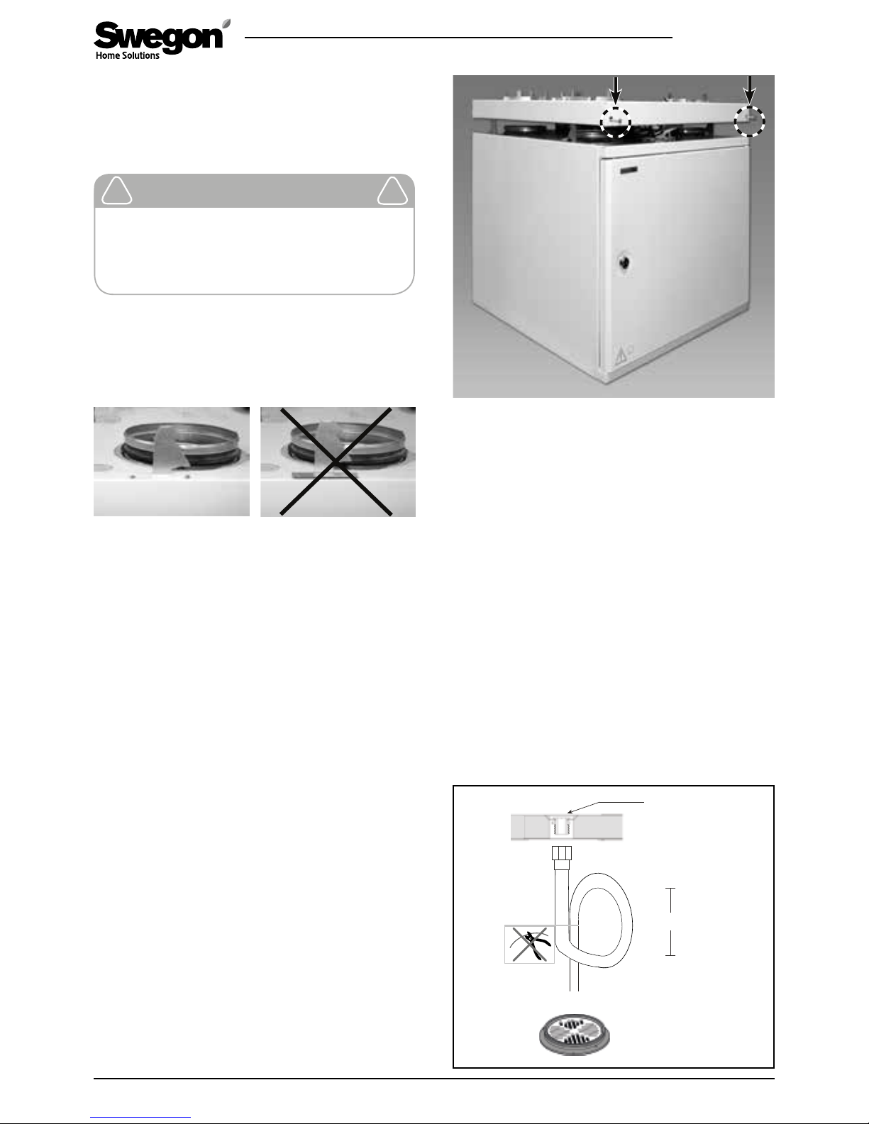
There is a metal water trap available as an accessory
(UVL).
Check that the condensate discharge outlet is not
clogged and check its outflow by pouring water on
the bottom of the ventilation unit. The condensate
discharge connection is located on the rear of the unit
under the rotary heat exchanger.
2.3 Ducts
Install the ventilation ducts, sound attenuators, sup-
ply air diffusers, air intake grilles and exhaust air ducts
as shown in the ventilation drawings. To prevent the
propagation of sound, do not install the ducts directly
against structural building elements.
Insulate the ventilation ducts in order to reduce loss of
heat or cooling energy and to prevent water from con-
densing on surfaces. In addition, it is advisable to insulate
the ducts to prevent the spread of fire. It is of greatest
importance to insulate cold ducts without gaps in
the insulation, so that moisture cannot condense.
2.4 To seal around duct penetration collars
It is advisable to use a mounting frame for sealing the
moisture barrier in the attic tie beams.
It is important to the preserve the tightness of the
vapour barrier at the duct penetration collars. A building
element penetration seal (accessory) will facilitate this.
This item is available in sets of 3 pieces, for diameters:
100, 125 and 160 mm and are attached to the moisture
barrier with tape.
Cut up the openings with approx. 10 mm smaller diam-
eter than that of the ducts. Secure the mounting frame
in the ceiling with screws through the holes on the
sides. The plastic film of the vapour barrier should either
be stretched and fastened between the mounting frame
and the structural element of the building, or be taped
tightly against the mounting frame.
The thickness of the insulation and the nature of the
surface layer of the ventilation ducts vary depending on
insulation material, climate zone and national standards
in force. For this reason, Swegon does not offer any rec-
ommendations for insulation thickness. Most manufac-
turers of insulation material offer calculation programs
for the calculation of sufficient and correct insulation.
In renovation projects, it is advisable to examine the
existing ducts to determine whether they are sufficiently
and correctly insulated. Insulating in the right way is
necessary for the ventilation unit to operate correctly. If
the ducts are uninsulated, even across a small area,
there is a high degree of risk of condensation and
indirect damage.
The supply air duct should be fitted with acoustic insula-
tion along the stretch between the unit duct outlet and
the sound attenuator, so that fan sound will not be
propagated out into the room.
In general, ventilation ducts should be insulated in the
following manner:
• Insulate outdoor air ducts run through warm spaces.
• Exhaust air ducts should always be insulated in ac-
cordance with national regulations. See separate pro-
ject planning instructions (for example Fire resistance
classification requirements).
• Insulate supply air ducts in cold spaces.
• Insulate extract air ducts in cold spaces.
• If the air inside the duct is colder than in the sur-
roundings; the insulation should be protected by a
vapour barrier.
2.5 Electric and control cables
A 1.5 m long cable with earthed plug-in contact is fitted
to the ventilation unit for measuring the voltage. The
cable extends from the top of the unit. The mains plug
serves as the ventilation unit’s main switch and it should
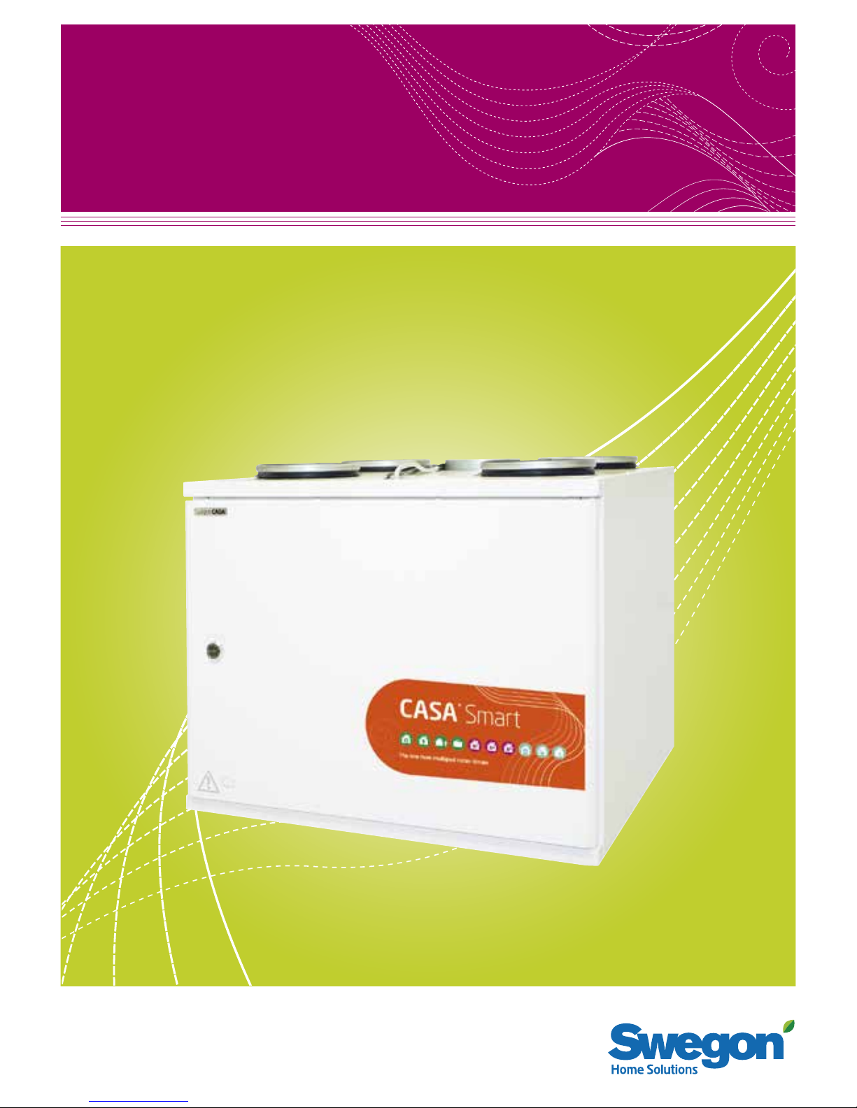
Important
Check whether the ventilation unit has
been supplied in the right-hand or left-
hand version to make certain that you are
connecting the ventilation ducts to the
correct duct connection spigots on the unit.
Check the ventilation plans to make sure
that the duct connections are correctly in-
stalled. See also the dimensional drawings
in the Section entitled: “Technical data”.
!!
Important
Even small gaps in the insulation impair the
sound attenuation and bring about a risk of
condensation and consequential damages.
!!
Important
Before commissioning the ventilation sys-
tem, check that the ventilation unit, filters,
condensation drain and ducts are clean and
that there are no loose objects inside them.
The ventilation ducts should be cleaned
regularly and always when the home is
renovated.
!!
Important
It is absolutely forbidden to operate the
ventilation system during the construction
period or if dust-raising work is carried out.
Before installing the unit, the ducts should
be blanked off with covers to prevent the
entry of impurities.
!!

W4.311016
Swegon reserves the right to alter specifications.
9
www.swegonhomesolutions.com
be connected to an electric socket at an easily acces-
sible spot. For power required, see the Section entitled:
“Technical data”.
On top of the ventilation unit are two modular cables
for control of the unit. The maximum connected length
of the modular cable in the system is 40 metres. If you
lengthen the modular cable within some building ele-
ment (e.g. in a wall), you should lengthen the cable in a
∅ 20 mm conduit, anticipating a possible later change
of cabling.
When installing the unit, make sure that you provide
adequate access to the connector of at least one cable,
e.g. for servicing and adjusting the unit, if and when the
need arises.
In multi-storey buildings, a control panel can be used as
a so-called hand-held micro terminal in conjunction with
service and installation work.
The connection of possible accessories is described in the
wiring diagram in the Section entitled: ”Technical data”.
The cables for accessories are not included in the supply.
2.6 Bypass for kitchen
The cooker hood is usually connected to the ordinary
extract air duct. However the cooker hood can be
connected to the ventilation unit’s separate extract air
connection, in order to meet national regulations or for
achieving a more effective than normal extract airflow.
The extract air from a compatible Swegon CASA cooker
hood can be conveyed via a duct to an extra duct con-
nection on the top of the ventilation unit. The duct be-
tween the cooker hood and the ventilation unit must be
installed in such a way that makes it possible to clean it.
The ventilation unit can be controlled from the cooker
hood control panel.
Important
If any further electrical wiring is required,
only a qualified electrician shall be allowed
to carry out this work.
The electric and control cables are located
on the upper side of the ventilation unit.
Make sure that the electric cable can be con-
nected to a wall outlet without obstruction.
!!
Important
The bypass for a kitchen is intended for use
when the airflows from the cooker hood/
kitchen are boosted. The kitchen’s general
ventilation must take place via the extract
air duct. If the general ventilation takes
place continuously via the cooker hood, the
supply air and extract air flows through the
heat exchanger will be out of balance, and
this will lower the efficiency and impair
the ventilation unit’s anti-freeze protection
functions during the winter.
!!

10
W4.311016
Swegon reserves the right to alter specifications.www.swegonhomesolutions.com
2.7 Installation of the Smart control panel
A maximum of two Smart control panels can be con-
nected to the ventilation unit, with different mutual ID
numbers. A 20 metre long modular cable is included to
connect the control panel. Run the cable to the desired
place where the panel will be mounted. A Smart control
panel can be mounted up to 40 metres from the unit
(using 2 x 20 metre long modular cables).
The front panel on the Smart control panel is released
using a screwdriver to push the retaining clips through
the holes on either side.
If several control panels are connected in chain, the
middle panel’s bus termination is moved to the “Open”
position. The jumpers do not need to be adjusted if only
one control panel is used.
The modular cable connected to any outlet socket on
the panel.
Finally, refit the front panel.
Bus termination: OpenBus termination: Terminated
2.8 To connect water pipes in the Econo model
The pipe connections of the Econo model should be ar-
ranged inside the ventilation unit. The connection work
will be facilitated if you temporarily remove the heat
exchanger and filter from the unit. Connect the inlet
flow pipe to the thermostat (3/8” female threads) and
the return pipe in the coupling with Ø 15 mm on the
ball valve.
The Econo model requires a continuous circulation
of hot water during the heating season.

W4.311016
Swegon reserves the right to alter specifications.
11
www.swegonhomesolutions.com
The ventilation system’s settings in connection with
commissioning and servicing are made from the pass-
word-protected “Settings” menu on a Smart control
panel. To open the menu, enter code 1234. (The code
can be changed). In conjunction with commissioning,
you always need to set at least the airflow and carry out
any adjustments to the Smart sensor if fitted.
3.1 To set the airflows
For estimated values for setting the airflows, use the
sizing curves in the Section entitled: ”Technical data”. A
qualified person should set the ventilation unit’s and the
ventilation equipment’s airflows using appropriate meas-
urement equipment.
As an initial value for ventilation planning, you can use
the ventilation value 0.5 times the volume of the build-
ing per hour + 6 l/s supply air per person, when the unit
is operating in the Home mode. (Initial values can vary
in different countries.)
In new homes, there is still construction moisture and
the house initially requires higher ventilation in order to
remove the moisture from the building. A great deal of
moisture in the home manifest itself in the form of mois-
ture on cold surfaces. We recommend that in new houses
to use higher volumes of air at first to remove moisture.
All the fan modes must be preset so that the venti-
lation unit will operate correctly. Fill in your entered
settings in the commissioning report.
It is recommended in order to improve the efficiency of
the ventilation to use an automatic moisture sensor or
to actively use the ventilation unit’s boost speed, if there
is a sauna, pool or equivalent moisture producer in the
home.
3. Commissioning
3.1.1 Setting the fan speeds
Before you start to adjust the fan speeds, ensure that
the filters are clean and that there are no foreign objects
or debris inside the ventilation unit.
Choose commissioning mode from the “Fan speeds”
menu, as the ventilation fans then run at the speed be-
ing set. In commissioning mode, all functions that affect
the speed of the ventilation unit’s fans, such as the anti-
freeze protection, are disconnected.
Set the fan speeds for all operating modes (Home/Away/
Boost) and the largest automatic boost, if you wish to
limit the Smart functions.
Fill in your entered settings in the commissioning report.
3.2 Smart functions
Setting of Smart functions must be performed.
Settings
Fan speeds
Preheater
Re-heater
Input settings
Smart functions
Fireplace function
Smart settings
Summer mode
Supply air limit
DDC control
Damper actuators
Sensors
Alarms
Reset factory settings
Change service code
Fan speeds
Commissioning mode
Away (supply)
Away (exhaust)
Home (supply)
Home (exhaust)
Boost (supply)
Boost (exhaust)
Max Smart boost (supply)
Max Smart boost (exhaust)
30%
30%
50%
50%
80%
80%
100%
100%
Important
Set the fan speeds in accordance with na-
tional regulations when you commission
the ventilation system. The system should
be commissioned by a qualified person,
and the airflows must not be changed on
one’s own responsibility, since doing so
could disrupt the way the ventilation sys-
tem operates.
!!

12
W4.311016
Swegon reserves the right to alter specifications.www.swegonhomesolutions.com
The value ”RH now”, the current moisture level, is
shown on the settings menu.
The automatic humidity system measures the daily
average value in the extract air and compares this with
the current value. The ventilation starts to be boosted
variably when the humidity has risen as much as the
Boost limit value.
When the sauna is working, the ventilation is boosted
with the set value, through the activation of the auto-
matic sauna limitation. This function prevents variations
in the fan speeds while the sauna is working.
3.2.4 Automatic air quality control
The function is available only on models equipped with
automatic air quality. Automatic air quality boosts the
ventilation variably according to the indoor air quality.
This function should always be set in conjunction with
commissioning.
The settings menu shows the value “AQ now” the
current air quality level. The function is set by specifying
the boost limits where you want the ventilation boost
to start and the value at which you want the ventilation
unit to reach maximum boost. Appropriate values can
be established based on the “AQ now” value shown in
the menu.
If it seems that the ventilation system reacts too quickly
to changes in the air quality level, you can increase the
filtering time.
3.2.5 Cooker hood function
The cooker hood function balances the ventilation when
the cooker fan is used to help prevent excessive nega-
tive pressure and improves fume extraction capability
of the cooker hood. The function starts automatically
when the damper in a compatible cooker hood is
opened and runs until the damper is closed.
3.2.1 Selection of Smart functions
Select which functions are to be available from the
“Smart functions” menu. When boost is selected,
boosting is used on all connected sensors.
3.2.2 Automatic Home/Away/Boost system
The function is available only on models equipped with
a carbon dioxide sensor. The automatic control system
controls the ventilation airflow variably according to the
carbon dioxide level in the home.
This function should always be set in conjunction with
commissioning.
The settings menu shows the value ”A+now” the cur-
rent level of carbon dioxide. The function is set by defin-
ing the limits values Home and Away. A suitable Home
limit value can be determined by reading the ”A+now”
value from the menu when a normal number of people
are in the home. Similarly, you can determine the Away
limit value by reading the “A+ now” value when the
property has been empty for several hours.
3.2.3 Automatic humidity system
The function is available only on models equipped with
a humidity sensor. The function boosts the ventilation
according to the normal moisture load caused by a
person, for example, when a shower adds extra moistu-
re to the residence. If the relative humidity of residence
rises above 60% over a longer period, the set airflows
must be increased, and the reason for the high level of
moisture investigated.
Smart functions
Fireplace function
Travelling
Cooker hood function
Central vacuum function
Boost
Summer mode boost
Heating boost
Shut down
Auto Home/Away/Boost
A+ now 950 ppm
Home limit
Away limit
Filter time
900 ppm
600 ppm
1 min
Auto humidity control
RH now 30 %
Boost limit
Full boost limit
Sauna function
5 % + RH
30 % + RH
Sauna boost 5 %
Auto Air Quality control
AQ now 620 ppm
Boost limit
Full boost limit
Filter time
800 ppm
1400 ppm
1 min

W4.311016
Swegon reserves the right to alter specifications.
13
www.swegonhomesolutions.com
Cooker hood function
Run time 30 min
Home state Compensation
Boost state Compensation cor.
Allow exhaust fan slowdown
20%
0%
Choose to permit a speed reduction of the extract air
fan when using a cooker hood whose extract air does
not pass through the ventilation unit.
Enable the cooker hood function and set the Home
mode’s compensation value so that the airflows are kept
in balance. Fine tune the boost compensation value too
if necessary.
3.3 Sensor
Select which sensor you wish to use to measure the
room air temperature.
The menu shows the temperature measured by the se-
lected sensor. If, for example, the temperature measured
by the sensor differs from the value from a temperature
sensor installed in a different location in the same room,
the temperature sensor can be calibrated by changing
the room air fine tuning value.
3.4 Control functions with optional items
of equipment
If the unit is to be controlled with optional equipment,
set the switch input for this.
There are three switch inputs on the ventilation unit’s
PCB that need to be configured. Specify which switch is
connected to each input. The options are input signals
from the following external switches: fireplace, travel-
ling, central vacuum, cooker hood, boost and filter
guard. You can change the relative priority of the func-
tions if necessary.
3.5 Remote supervision (DDC)
If the ventilation unit is to be operated remotely, choose
to put remote control into service and set the desired
temperature reductions. If the ventilation unit’s fan
control is handled by DDC, you cannot change the oper-
ating mode from the Smart control panel. See a detailed
description of remote control in the section “Technical
data” / “Supervision (DDC)”.
Variable control occurs between the voltages 2 V - 5 V
- 8 V. The ventilation then switches variably between op-
erating modes Away - Home - Boost. Otherwise, control
is performed according to the normal DDC control.
3.6 Damper motors
If external duct damper motors are used, choose to en-
able control. The damper is then regulated to the open
position when the ventilation unit is operating.
3.7 Re-heater (not Econo)
Here you select whether you wish to use the electric air
heater for re-heating to heat the supply air when the
heat exchanger’s power is not sufficient for reaching the
preset supply air temperature.
3.8 Anti-frost protection
Anti-frost protection works automatically.
3.9 Restore factory settings
Resets all settings made from the control panel, with the
exception of the fan speeds.
Damper actuators
Damper actuators
Sensors
Room air
Room air temperature
Room air fine tuning 0,0°C
22,2°C
UP1
Re-heater
In use
Input settings
Input 1
Priority
Input 2
Priority
1
Hood
1
Fireplace
Input 3 No selected
DDC control
Fan control
Temperature control
Emergency stop
Temperature drop (away)
Temperature drop (travelling)
Stepless control
2°C
0°C
Important
Smart measurements: CO2, RH ja VOC.
The absolute values in the measurement
result does not affect how well the control
works.
!!

14
W4.311016
Swegon reserves the right to alter specifications.www.swegonhomesolutions.com
4.1 Service reminder
The service reminder is activated with preset time inter-
vals and the symbol is displayed on the control panel’s
screen. As a factory setting, the service reminder is not
in operation. It can be put into operation under the
main menu item “Diagnostics”/”Service reminder”. The
recommended service interval for the ventilation unit is
six months.
When servicing has been performed, the service remind-
er is reset from “Alarm” in the main menu.
4.2 To open the ventilation unit
Before you begin any service work, isolate the power
supply voltage to the ventilation unit by pulling out its
electric plug from the wall socket. Wait a few minutes
before you open the inspection door of the ventilation
unit so that the fans have time to stop and possible air
heaters have time to cool down.
The inspection door can be opened by turning the lock
bolt with a screw driver for slotted screw heads.
4.3 Filter
The filters should be replaced at least every six months.
The filters may need to be cleaned or replaced more often
in homes where there is considerable dust or if there are
many impurities in the outdoor air.
The ventilation unit must not be operated without filters.
Use only filters recommended by Swegon in the ventila-
tion unit. This is important, as filters with exactly the same
appearance and size can have very different pressure losses
and filter capacity. If an incorrect filter is used, it is not cer-
tain that the ventilation unit will work as designed. Check in
the list of components that you have selected correct filters.
4.4 Heat exchanger
You should check the condition of the heat exchanger
whenever you service the unit.
Withdraw the heat exchanger from the unit for inspec-
tion. Do not damage the heat exchanger fins.
Make sure that the passages through the heat exchang-
er rotor are not clogged and clean them e.g. with run-
ning warm water if required. Never use cleaning agents.
The passages of the heat exchanger should be dry
before you reinstall the heat exchanger in the unit.
4.5 Fans
The ventilation unit’s fans must be checked at least
every two years.
Before you remove the fans, you must dismantle the
extract air filter and the heat exchanger from the venti-
lation unit. Then disconnect the plug-in contacts of the
fans (note the locking claws on the side of the contact.
Then unscrew the locking bolts located on the partition
wall of the ventilation unit.
4. Service
Important
The ventilation unit must not be operated
without filters! Use only filters recom-
mended by Swegon in the ventilation unit.
Find the correct filter in the Section enti-
tled: ”Technical data”.
!!
3.10 Change the service code
This menu is used to change the code to access the set-
ting menu.
3.11 Use
Issues with reference to the usage of the ventilation
system are dealt with in the instructions for use supplied
with the unit.
Enter code
Accept
[ 12 3 4 ]

W4.311016
Swegon reserves the right to alter specifications.
15
www.swegonhomesolutions.com
Undo the locking devices and tilt the lower part of the
fan toward the rear wall until the fan disconnects from
the mounting bracket behind. Finally, turn the fan side-
ways and work it out of the ventilation unit. Be careful
not to damage the insulation on the electric cables.
If necessary, clean with a soft brush. Be careful not to
dislocate the impeller balancing weights. If significant
amounts of dirt collect on the fan impeller cleaning
should be left to a professional.
Reinstall the fans by inserting them and turning them
near their final positions. Tilt the lower part of the fans
toward the rear wall and move the discharge section
of the fan along the side wall toward the rear locking
device. Straighten the fan and push the locking bolt into
position though the cover in the partition wall and fasten
it at the intermediate wall with two screws. Connect
the plug-in contacts and install the heat exchanger and
extract air filter into position.
4.6 Other servicing
Clean the inner surfaces of the ventilation unit by
vacuum cleaning or with a damp cloth, if needed.
Check that the condensate discharge outlet is not
clogged and check its outflow by pouring water on
the bottom of the ventilation unit. The condensate
discharge connection is located on the rear of the unit
under the rotary heat exchanger.
1.Supply air filter
2.Extract air filter
3.Heat exchanger
1.Extract air fan
2.Supply air fan
3.Condensate discharge connection
4.The fan’s locking device
5.The plug-in contact the fans
1
2
3
1
2
3
4
4
5

16
W4.311016
Swegon reserves the right to alter specifications.www.swegonhomesolutions.com
5. Alarms and Troubleshooting
5.1. Alarms
Any disruptions to the function of the ventilation unit
are indicated by symbols on the upper row of the base
display. If there is an active alarm in the system, the
screen leaves its standby mode and does not enter
standby mode again as long as the alarm is active. The
symbol for an active alarm is . The condition that
has caused the alarm is shown by the “Alarm” item
on the main menu. A so-called info-alarm remains on
the screen when the active fault condition ceases.
The Info alarm can be reset from “Alarm” on the main
menu.
5.2 Troubleshooting
A ventilation system is a unified whole composed of
several system components all of which influence how
the system operates. A malfunction in ventilation perfor-
mance could be caused by any component of the ventila-
tion system or by the way the system has been installed.
If during the ventilation unit’s warranty period (2 years)
after a check (see the enclosed check list) there are func-
tional disruptions in the ventilation unit, you can register
these using the response form at the address www.
casahelp.fi. There are also instructions, service videos and
frequently asked questions on the same website.
If a problem or a fault occurs on the ventilation system
after the warranty period (2 years), contact our network
of authorised service companies on www.swegonhome-
solutions.com, your real estate company’s service divi-
sion or another service company that is fully conversant
with ventilation repairs.
Status Alarms Action
T1...T8 sensor fault Contact a service company. The ventilation unit runs in a restricted operating
mode.
Reheater error Check the overheating protection. Contact a service company.
Preheater error Check the overheating protection. Contact a service company.
Freeze risk water-heated air
heater
Ensure that the circulation pump in the waterborne heating system is running
and that the water supply to the ventilation unit’s heating coil is hot enough.
Fault supply air fan Contact a service company.
Fault extract air fan Contact a service company.
Contact fault Restart the ventilation unit. Contact the service company if the error persists.
External emergency stop/
fire alarm
The alarm clears automatically when the external emergency stop or the fire
alarm ceases. No info alarm remains afterwards.
Internal fault Restart the ventilation unit. Contact the service company if the error persists.
The ventilation unit runs in a restricted operating mode.
Service reminder Service the ventilation unit and acknowledge the service reminder.
Filter guard Replace the filter and reset the filter guard.
Important
Freeze protection function
Ice can form in the heat exchanger during
periods of cold weather if the extract air
is humid. A protective function then auto-
matically reduces the speed of the supply
air fan. Under such conditions, variations in
the fan speed are therefore normal.
Under such conditions, small amounts of
ice can form inside the ventilation unit.
!!

W4.311016
Swegon reserves the right to alter specifications.
17
www.swegonhomesolutions.com
For users of the Swegon CASA ventilation unit
Thank you for your excellent choice of energy efficient ventilation for your home. Swegon designs, manufactures, mar-
kets and sells Swegon CASA ventilation units and cooker hoods. Swegon guarantees the functionality of the manufac-
tured units and grants a warranty for them. A ventilation system is a unified whole composed of several system compo-
nents all of which influence how the system operates. This check list is meant for use by specialists in the building trade
and for residents who suspect malfunctions in the ventilation.
Malfunctions in ventilation performance
A malfunction in ventilation performance could be caused by any component of the ventilation system or by the way the sys-
tem has been installed. Normal operation of the Swegon CASA ventilation unit is described in the user’s instructions supplied
with the unit on delivery. If malfunctions occur in the ventilation system, ensure the following with the help of a professional:
CHECK LIST
If the above-stated checks are not carried out and representatives for Swegon or an authorized service company disco-
ver inadequacies in them, the client is responsible for the costs for the service visit, even during the warranty period. If
a ventilation unit under warranty is still marred by functional disruptions after the checks, submit a contact request on
our web site www.casahelp.fi. If a problem or a fault occurs on the ventilation system after the warranty period (2 yea-
rs), contact our network of authorised service companies on www.swegonhomesolutions.se, your real estate company’s
service division or another service company that is fully conversant with ventilation repairs.
1) Make sure that the pipes have been insulated fully according to the instructions and that the insula-
tion reaches all the way up to the ventilation unit so that no uninsulated surface is visible.
-> Even a small gap in the insulation could cause among others condensation and acoustic problems.
2) Make sure that the pipes’ connections to the ventilation unit are tight and that the unit is installed horizontally.
-> If the connections have not been fitted correctly, condensation and acoustic problems could arise.
3) Make sure that the ventilation unit is equipped with Swegon’s original filters. This will ensure
pressure differentials and the filtration values that conform to the design level, enable the unit to
operate correctly and maintain a healthy indoor climate in the home. Make also sure that the filters
are clean and replace them when needed. Check also the fresh air grille and clean it if needed.
4) Check that there are no unnecessary objects or impurities inside the ventilation unit. At the same
time, make sure that the condensate drain in the bottom of the ventilation unit is not clogged by
impurities or insects. The condensate drainage function can be checked by pouring a few drops of
water on the bottom of the ventilation unit.
5) If the ventilation unit is equipped with electric air heaters, make sure that the excess temperature
cut-out switches have not tripped. The excess temperature cut-out can be manually reset by pres-
sing a button according to the user’s instructions.
6) Make sure that the ventilation unit’s inspection cover is closed and that it seals tightly along its enti-
re periphery against the unit casing.
7) Check that the airflow rate settings have been set according to the ventilation plan and that the
airflow rates to and from the ventilation unit’s air heater are in balance (the supply air flow must be
2–10 % less than the extract air flow).
8) Make sure that the fan speeds have been preset for all the operating modes (Away, Home, Boost).
If the fan speed settings do not deviate from the factory settings presented in the instructions, there
is reason to suspect inadequate commissioning/adjustments.
9) Make sure that a correctly recorded and approved measurement record is available.
Items to check

18
W4.311016
Swegon reserves the right to alter specifications.www.swegonhomesolutions.com
6. List of components
1. Temperature sensor
2. Fan package (W4, R model):
- Supply air fan: PWEC175L
- Extract air fan: PEC119R
Fan package (W4, L-model):
- Supply air fan: PWEC175R
- Extract air fan: PEC119L
3. Air heater, pre-heating: 60369
4. Air heater, reheating: 50269
5. EC circuit card: 603010
6. Door contact: 60542
7. Set of filters: W304FS
8. Heat exchanger: 61033
9. Door: DPW100RL
10. Damper motor: 60348
11. Air heater, reheating (Econo, R model): 620220
Air heater, reheater (Econo, L model): 620221
12. Condensate discharge tube: 502103
2
210
11
7
48
53
6
7
9
1
12
*) Included
*) W4 models W04VR05S110A
W04VL05S110A
W04VREES110A
W04VLEES110A
Lisävarusteet
• Smart control panel: SC10*
• Modular cable, 20 m: PMK20*
• Mounting frame with vapour barrier (R/L): PR100YP
• Water trap: UVL
• Ceiling mounting frame (R/L): PW100KA
• Wall mounting bracket: PW080SAT*
• Filter replacement kit, F7, G3 + heat resistant filter:
W304FS

W4.311016
Swegon reserves the right to alter specifications.
19
www.swegonhomesolutions.com
7. Technical data
7.1 Fan outputs (EN 13141-4)
Air flow
Pressure differential, Pa
Supply airflow
Extract airflow
7.7.1 W4
7.1.2 W4 Econo
Air flow
Pressure differential, Pa
Supply airflow
Extract airflow
0
50
10
0
15
0
20
0
25
0
30
0
35
0
40
0
450
0102030405060708090100 110
60%
50%
40%
30%
100%
90%
80%
70%
SFP 2.0
SFP 1.5
SFP 1.0
0
50
100
150
200
250
300
350
400
450
0102030405060708090100 110
100%
90%
80%
70%
60%
50%
40%
30%
SFP 2.0
SFP 1.5
SFP 1.0

20
W4.311016
Swegon reserves the right to alter specifications.www.swegonhomesolutions.com
7.2 Outputs of the components
W4 W4 Econo
Connection 230 V, 50 Hz, 10 A 230 V, 50 Hz, 10 A
Fans 290 W 290 W
Air heater, pre-heating 1000 W 1000 W
Air heater, reheating 500 W -
Total output 1300 W 1300 W
Power consumption
7.3 Acoustic data
Fan
setting
%
Sound power level broken down into octave bands, Lwokt, dB Total assessed
sound power level
LWA, dB(A)
63 Hz 125 Hz 250 Hz 500 Hz 1,000 Hz 2,000 Hz 4,000 Hz 8,000 Hz
40 71 57 52 49 47 37 31 22 52
50 75 64 58 55 53 45 40 32 59
60 77 70 64 59 59 51 47 40 65
70 81 71 68 63 64 57 53 46 69
80 82 72 72 67 66 61 57 51 72
90 86 76 75 70 68 66 62 57 74
100 86 77 76 72 70 69 65 60 77
Fan
setting
%
Sound power level broken down into octave bands, Lwokt, dB Total assessed
sound power level
LWA, dB(A)
63 Hz 125 Hz 250 Hz 500 Hz 1,000 Hz 2,000 Hz 4,000 Hz 8,000 Hz
40 70 49 45 41 35 28 18 18 46
50 73 56 48 44 38 31 22 19 50
60 73 60 53 48 42 36 28 23 52
70 75 62 57 52 45 41 33 27 55
80 76 63 60 56 48 44 36 30 58
90 79 64 62 57 49 47 38 33 60
100 81 68 64 60 51 49 40 35 62
Fan
setting
%
Sound power level broken down into octave bands, Lwokt, dB Total assessed
sound power level
LWA, dB(A)
63 Hz 125 Hz 250 Hz 500 Hz 1,000 Hz 2,000 Hz 4,000 Hz 8,000 Hz
40 68 53 45 40 31 28 16 18 45
50 71 56 49 43 33 31 19 20 48
60 72 61 54 47 37 35 24 21 52
70 75 63 58 51 41 39 28 23 55
80 75 66 62 54 44 42 30 24 58
90 77 67 64 57 46 44 33 28 60
100 75 68 65 58 47 46 35 28 61
Sound emitted to supply air duct
Sound emitted to extract air duct
Sound emitted to outdoor air duct
Total capacity, W
Air flow
0
l/s
m3/h
36 72 108 144 180 216 252 288 324
0
25
50
75
100
125
150
175
200
225
250
275
0102030405060708090 100 110
100%
90%
80%
70%
60%
50%
40%
30%
360 396
Other manuals for CASA W4 Smart
2
Table of contents
Other Swegon Air Conditioner manuals

Swegon
Swegon ADRIATIC VFc User manual

Swegon
Swegon GOLD PX User manual

Swegon
Swegon GOLD series User manual

Swegon
Swegon DVCe Guide

Swegon
Swegon ILTO W80 Parts list manual

Swegon
Swegon bluMartin freeAir 100e User manual

Swegon
Swegon PARASOL b Series Guide

Swegon
Swegon PARASOL C Series Guide

Swegon
Swegon TBKA/TCKA User manual

Swegon
Swegon EAGLE Wall b Guide