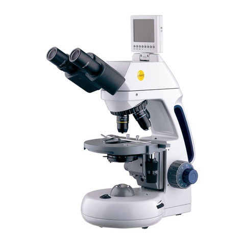
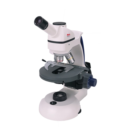
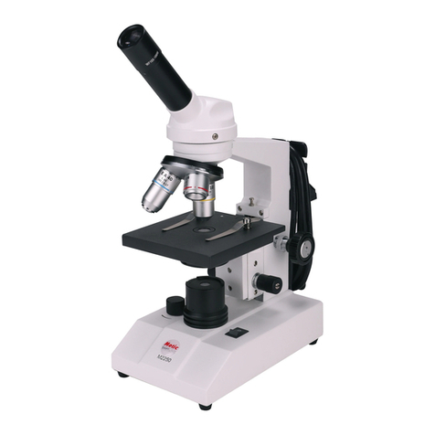
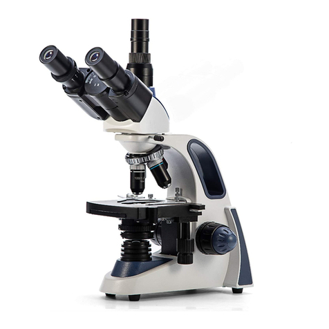
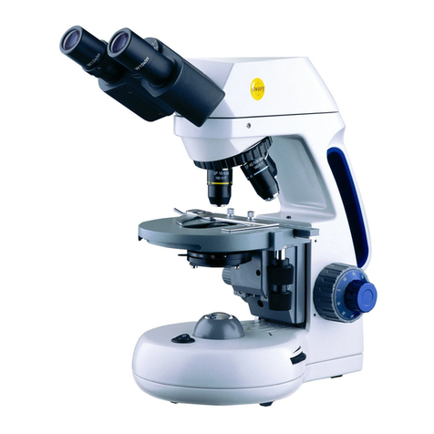
Swift M3500 SERIES User manual

1
SWIFT M3500 SERIESMICROSCOPE
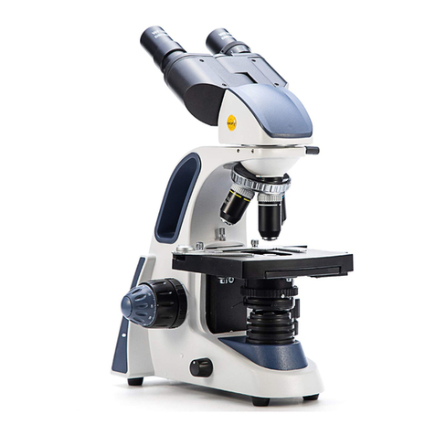
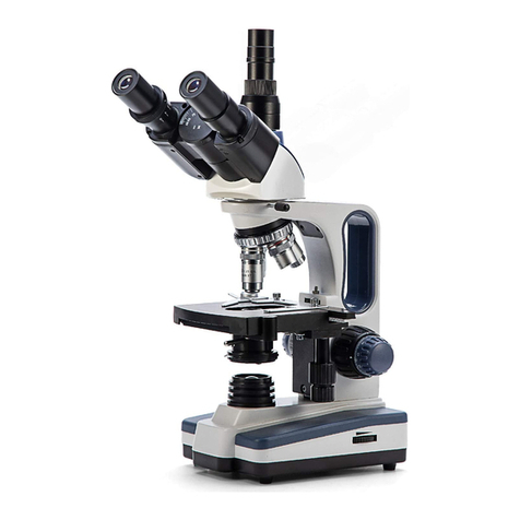
The SwiftM3500 Series microscope is considered tobe the most“Student
proof” microscope on the market. It is an instrument of optical and
mechanical precision and will perform satisfactorily with minimum
maintenance.

2
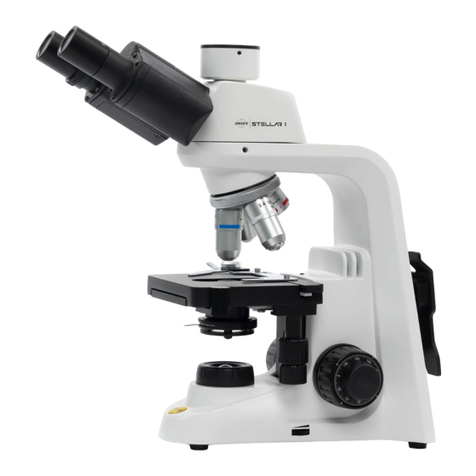
MICROSCOPE COMPONENTS
ARM - the vertical column (attached tothe base) which supports the
stage and contains the coarse and fine adjusting knobs and focusing
mechanism.
BASE - the housing and platform of the instrument to which the arm is
attached. The base stands on rubber feet and contains the illuminator
assembly.The bulb replacement part number isprintedonthe underside
of the base.
COARSE FOCUS CONTROL MECHANISM - this model is a stage focusing
model meaningthestage moves up ordown by meansof a brass rack and
steel pinion gear tobring the specimen intofocus. The movement is
achieved bytwolargeknobs onthe sides ofthearm. Inorder to prevent
gear damage, the focus controlis equipped with aslipclutchthat allows
slippage atbothendsofthe focusing range. The system isalso furnished
with a tension control toprevent “stage drift”.
CONDENSER – the condenser is mounted in the stage and it is used in
conjunctionwith the iris diaphragm. The functionof the condenser is to
provide full illumination tothe specimen plane and toenhance the
resolution and contrast of the object being viewed.
CORD HOLDERS - Apair of half-circle brackets installed on the back of
the arm which are used tostore the electrical cord.
DISC DIAPHRAGM - The wheel-shaped disc attached tothe underside of
thestage.It hascircular openings, called apertures, and may berotated
toalign any of the apertures with the optical path.
EYEPIECES - the upper optical element that further magnifies the
primary image of the specimen and brings the light rays in focus at the
eyepoint. The eyepiece has a calibrated POINTMASTER®scale for taking
measurements.
FIELD CONDENSER -Alens located in the light housing which intensifies
the light from the illuminator in the base.
FINE FOCUSCONTROL MECHANISM - thefine focusingknobs, locatedon
either side ofthe microscope, in front ofand slightly lower than the

3
coarsefocusingknobs, areused forprecisefocusingadjustmentsonce
the specimen has been brought intoview with the coarse focus controls
HEAD - it is the top portion of the microscope that contains the
refractingprisms and the eyepiece tube. The eyepiece is lockedonto the
eyepiece tube with a set screw.The head rotates allowing operation of
the microscope from thefrontortheback, and allowsthe microscope to
be shared by simply rotating the head.
IRIS DIAPHRAGM - a round multi-leafdevice mounted below the
condenser which is controlled by alever. It issimilar toacamera shutter
and controls the amount of light entering the condenser, allowing the
user to control contrast. Iftheimage is“washed out” theiris diaphragm
is opened too wide. Ifthe image is too dark the iris is not open wide
enough.
MECHANICALSTAGE - An alternative to stage clips is aMechanicalStage.
A Mechanical Stage holds the slide in place, allowing the user tomove
the slide on any x/y axis through the manipulationof two control knobs
or a co-axial control mechanism.
NOSEPIECE - the revolving turret that holds the objective lenses,
permitting changes in magnification by rotating different powered
objective lenses intothe optical path. The nosepiece must “click” into
place for the objectives tobe in proper alignment.
OBJECTIVES - TheDINobjectives are standard in the industry, with large
numerical aperture (N.A.) topermit maximum resolution. All objectives
are achromatic, color-coded and parfocaled at a 45mm distance. The
40XRD and the 100XRD are sealed tokeep oil residue from seeping into
the objective. These two objectives have a spring loaded tip toprevent
accidental breakage of either the slide or front lens of the objective if
they should come intocontact with each other.
Part No. Mag. N.A. Working Distance Field ofView Color Code
MA10071F 4X 0.10 14.83mm 4.50mm Red
MA10072 10X 0.25 6.32mm 1.80mm Yellow
MA10073S 40X 0.65 0.53mm 0.45mm Blue
MA10074 100X 1.25 0.23mm 0.18mm White
POWER SWITCH - turns the illuminator on and off.

4
STAGE - thetable ofthemicroscope wheretheslide is placed forviewing.
This component moves upward and downward when the focusing knobs
are turned.
STAGE CLIPS - Apair of flexible metal clips attached by spring screws
that hold the slide in position on the stage.
IMPORTANTMICROSCOPY TERMS
APERTURE, ANGULAR - The angle (or cone) of light rays capable of
entering the front lens of the objective from a point in the object. By
increasingthe angular aperture ofanobjective, morelight raysfromthe
specimen can be taken in by the lens; hence the resolving power is
increased.
COMPOUNDMICROSCOPE - amicroscopehaving aprimary magnifier (the
objective) and a second (the eyepiece) toboth conduct light, amplify
magnification and convert the image intoa field of view easily seen by
the human eye.
COVER GLASS - Thin glass cut in circles, rectangles or squares, for
covering the specimen, usually a thickness of 0.15 to0. I7mm. The
majorityof specimens should be protected by acover glass, and mustbe
covered when using 40XRD or 100XRD objectives.
DEPTH OFFOCUS - The abilityof a lenstofurnisha distinct imageabove
and belowthefocal plane. Depthof focus decreases with the increase of
numerical aperture or with the increase of magnification.
DIN – (Deutsche Industrial Norman) An international optical standard for
the manufacturing of most quality microscope lenses. Many DIN lenses
will be interchangeable from one DIN microscope toanother.
FIELD OF VIEW - the area of the object that is seen when the image is
observed. Itmayrangeindiameter from several millimeters tolessthan
0.1mm.
FOCAL LENGTH - parallel rays oflightafter refractionthroughalenswill
converge toa focus at the focal point. The distance from the optical
center of the lens tothe focal point is the focal length.

5
NUMERICAL APERTURE(NA) – a measure ofan objective’s light gathering
capabilities. The concept may be compared tothe F-valve in
photographic lenses. Generally speaking, objectives with N.A. values of
less than 1.00 are "Dry" objectives. Values of1.00 orgreater require oil as
amedium. Pleasenote thatcondensers are part of the optical system and
are alsoassigned an N.A. value. That value must be at least as high as
that of the highest objective used.
PARFOCAL - Aterm applied toobjectivesand eyepieceswhen practically
nochange in focus has tobe made when an objective of one power is
substituted for another.The DIN objectives on your Swift M3500 Series
Microscope are parfocaled at the factory toa standard 45mm distance,
sothat only a slight turn of the fine adjustment is required when a
change is made from a lower to higher power.
RESOLVING POWER - The ability of alens toclearly separate fine detail.
Resolvingpower isdirectly proportional to thenumerical aperture ofthe
optical system.
WORKINGDISTANCE – thedistancefromthe lensofthe objectivetothe
cover slip on the slide, when the specimen is in focus.
USINGYOURSWIFT M3500 MICROSCOPE
1. Use the stage clips or slide holder mechanism tosecure the slide in
place. Be sure the specimen is centered over the opening in the
stage.
2. Rotate the nosepiece toplace the lowest power (4X) objectiveover
the specimen. Be sure the objective “clicks” intoposition.
The disc oriris diaphragmshould be turned oradjusted tothelargest
aperture, allowing the built-in substage illuminator toprovide a
constant, even dispersion of light tothe optical system. The disc or
iris diaphragm is not intended tocontrol the brightness of the
illumination. The purpose of the diaphragm is tomatch the
numerical aperture of the objective. Smaller apertures increase
contrast in the image while large apertures decrease the contrast. A
good procedure in selecting the proper aperture is tostart with the
largest and reduce until the fine detail of the specimen is in exact
focus.

6
3. While viewing through the eyepiece, rotate the coarse focusing knob
tobring the specimen intoview.Next, sharpen the focus using the
fine focus knob.
4. Ifthe image of the specimen appears pale, the aperture of the
diaphragm should be decreased (ifthe model has a disc diaphragm,
rotate the disctoasmaller hole, conversely, ifthe model hastheiris
diaphragm, it should be closed slightly). This will increase contrast
in the specimen’s image. Ifthe specimen appears dark, slightly
open the diaphragm.
5. Rotate the nosepiece tothe next higher power objective. A slight
turn ofthefine focusing knobmay berequired tobring the imageof
thespecimeninto sharp focus. Oncethespecimenisinfocuswiththe
highest power objective, it will be in focus with each lower power
objective.
OIL IMMERSION (Only for modelswith a 100X objective)
When lightrays from the objective lens to thespecimenpass throughair,
they are distorted slightly, a phenomenon known as refraction. This is
usually not a problem at amagnificationof 400X orlower.However,at a
magnification of 1,000X and above, refraction becomes problematic.
This problemis reducedsignificantly by placinga thin layer of very clear,
viscousoil betweenthe slide and tip oftheobjective lens. The result is a
much clearer image at 1,000X because the oil has the same light
transmitting properties as glass. Using oil slightly increases the
resolutionand brightness ofthe image. Usually avery thin slide (size#1)
is used for oil immersion because at this magnification, the working
distance is very small and is critical tofocusing the specimen. Good
quality glass (not plastic) cover slips should be used. Iftheir thickness is
over 0.17mm, the objective will not resolve properly, because the
specimen cannot be moved close enough tothe objective lens tobe in
focus.
Place atinyamountofoil (only1drop should besufficient)ontotheslide
prior torotating the 100XRD objective intoposition. It is essential to
thoroughly clean the objective tip after use to prevent damage and to
ensure that an image can be seen clearly the next time the objectiveis
used. Please contactSwiftOptical or your authorized Swiftdealer forthe
appropriate immersion oil touse.
7
IMPORTANT: The working distances ofthe40XRD and 100XRDobjectives
to the slide surface are very small and although the oil immersion
objectives are sealed toprevent oil contamination, it is agoodpractice
toavoid draggingthese objectives through anoiled slide. The 100XRD oil
immersion lens onSwift microscopes has aspring-loaded end to prevent
cracking the cover slip uponits initial contact. Once this zoneof safety is
exceeded by moving the slide further toward the lens, a point can be
reached where damage will occur. Always make apractice of frequently
checking the position of the lens on the slide. Note that a 100XRD
objective requires an iris diaphragm for brightfield oil immersion
microscopy.
HOW TO USE THE POINTMASTER® EYEPIECERETICLE
Swift's patented POINTMASTER® eyepiece reticle, which is installed in
the eyepiece of the M3500 microscope, enables the user toeasily
measure the size of the specimen.
I. The numbers on the chart indicate the actual size of the
POINTMASTER® scale in millimeters. For example, the length is
1.0mm from the top of the arrow tothe bottom; the total length of
the scale is 8.0mm, etc. The thickness of all the horizontal lines is
0.01mm.
2. Toobtain the actual physical size of a specimen, divide the
POINTMASTER® scale readings by the magnificationof the objective
lens that is in use. Divide the readings by 10 ifthe 10X objective is
being used, 40 ifthe 40XRD objectiveis in use, or100if of 100XRD is
in use.

8
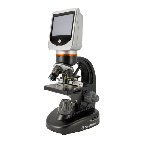
DIGITAL PHOTOGRAPHY
The M3501CL-DGL and M3503CL-4DGL models feature a built-in 1280 X
1024 pixel digital camera tocapture still images or videoclips on toa
computer. In order touse the camera, the software must first be
installed on a computer. The minimum computer requirements touse
the camera is havingan available USB 2.0 port,Windows XP, Vista orMac
OS Xoperating system installed on thecomputer, 512MBofRAM, 1GB free
hard drivespace and1Ghz CPU.Instructions onhowto install anduse
the software is included on the software CD that was packaged with
the M3501CL-DGL and M3503CL-4DGL microscopes.

9
PARTS AND ACCESSORIES
EYEPIECEREPLACEMENTS
MA10510 W10XD, 18mm Eyepiece
MA10511 W10XD, 18mm Eyepiece with Pointmaster
OBJECTIVEREPLACEMENTS
MA10071F 4XD Achromat Objective
MA10072 10XD Achromat Objective
MA10073S 40XRD Achromat Objective
MA10074 100XRD Achromat Objective
MISC. ACCESSORIES
MA268 Stage Clips (pair)
MA533 Dust Cover
MA12005 High-drive Mechanical Stage
MA12006 Low-drive co-axial Mechanical Stage
MA15383 Cord Holder (pair)
MA2202F 5W Fluorescent Bulb
MA2215 .06 W LED replacement lamp
CARE AND CLEANING
The M3500 Series microscope is designed tofunction with minimal
maintenance, but certain components should be cleaned frequently to
ensure ease of viewing. The power switch should alsobe turned off or
unplugged when the microscope is not in use.
CLEANING – The front lens of the objectives (particularly the 40XRDand
100XRD should be cleaned after use. First brush with a soft, camel hair
brush orblown off with clean, oil free air toremovedust particles. Then
wipe gently with a soft lens tissue, moistened with optical cleaner
(eyeglass or camera lens) or clean water. Immediately dry with a clean
lens paper.
CAUTION - Objectives should never be disassembled by the user. If
repairs orinternal cleaningshould be necessary, this shouldonly be done
by qualified, authorized microscope technician. The eyepiece(s) may be
cleaned in the same manner as the objectives, except in most cases
optical cleaner will not be required. In most instances breathing on the
eyepiece tomoisten the lens and wiping dry with a clean lens tissue is
sufficient toclean the surface. Lenses should never be wiped while dry
as this will scratch or otherwise mar the surface of the glass.

10
The finish of the microscope is hard epoxy and is resistant toacids and
reagents. Clean this surface with a damp cloth and mild detergent.
Periodically, the microscope should be disassembled, cleaned and
lubricated. This should only be done by a qualified, authorized
microscope technician.
DUST COVER AND STORAGE – All microscopes should be protected from
dust by a dust cover when in storage or not in use. A dust cover is the
most cost-effective microscope insurance you can buy. Ensure that the
storage space is tall enough toallow the microscope tobe placed into
the cabinet or ontoa shelfwithout making undue contact with the
eyepieces. Never store microscopes in cabinets containing chemicals
which may corrode your microscope. Also, be sure that the objectives
are placedin thelowestpossible position andtherotatingheadis turned
inward and not protruding from the base. Microscopes with mechanical
stages should be adjusted toward the center of the stage toprevent the
moveable arms of the mechanical stage from being damaged during
storage in the cabinet.
TENSIONCONTROLOFFOCUSING MOVEMENT - Tensionofthefocusing
movement is controlled by atension systemfound on the pinion metal of
therapid focuscontrol. Thiscanbeadjusted byusing the Swift part
#MT205 wrench.
BULB REPLACEMENT - Toprolongthelifeofthebulb youshould always
turn offthe unit when not in use. Thereplacement bulbpart number can
be found underneath themicroscopeonthe metal base plate. The
M3500DF models use a5Wfluorescentbulb Swiftpartnumber MA2202F.
The M3500CLmodels use a .06W LED Swift part number MA2215.

11
MA2202FFluorescent Bulb
To replace a bulb, you must first turn the power off and unplug the
microscope’s electrical cord from the electrical socket and remove
any slides on the stage. Carefully turn the microscope on its side,
unscrew and openthe hinged cover. Acabletieisusedto secure thebulb
tothe bulb socket and must be cut and removed. Make sure the bulb is
cool and remove it by carefully pulling the bulb out of its socket. Insert
the new bulb by seating the bulb firmly intothe socket. The bulb should
not need further alignment. Another small cable tie can be used to
secure the bulb tothe socket ifthe microscope is going tobe moved
around often. Close the hinged cover and tightenthe screw tohold the
hinged cover closed.
MA2215 LED
Toreplacean LED, youmustfirstturn the poweroff and unplug the
microscope’selectrical cord fromthe electricalsocket and removeany
slides onthestage. Use thesmall allen wrench(.09mm) that was
included withthemicroscopetoloosenthesetscrews thatholdthe
black illuminatorhousingontothebase ofthemicroscope. Removethe
illuminatorhousingto expose theLED. Simplypull theLED straightupto
removeitfrom thelightsocket. Alignthe 2metal socketpinswiththe
holesatthebottomofthenewLEDand pushtheLEDontothesocket.
Re-install the illuminator housing.
COMMON PROBLEMSIN MICROSCOPY
CAUTION – Never disassemble mechanical or optical components. This
servicing should only be done by an authorized Swift technician. The
Limited Lifetime Warranty will be null and void if the mechanical or
optical components are disassembled by a non-Swift dealer.
A. PROBLEM – NoIllumination
CORRECTION -
1. Is the power plug connected toan active A.C. outlet?
2. Is the on/off power switch working properly?
3. Check the bulb. Try a new bulb ifyou have one.
4. Check the contact points of the bulb and socket

12
B. PROBLEM – Illumination “hot spots” and uneven brightness in the
field of view.
CORRECTION -
1. Is the Abbe condenser in the correct position?
2. Are the nosepiece and objective clicked intoproper position?
C. PROBLEM – Image appears “washed out” or weak.
CORRECTION -
1. Slightly close the diaphragm to a smaller aperture
2. Objective lens is dirty. See “Care and Cleaning” Section.
3. Eyepiece is dirty. See “Care and Cleaning” Section.
D. PROBLEM – Dust or hairs seem tobe moving in the image.
CORRECTION – The iris diaphragm is not open wide enough. Slowly
open the diaphragm toincrease the size of the opening allowing
for additional illumination.
E. PROBLEM - Once the specimen is in focus, it moves out of focus
CORRECTION – Gravity is causing the stage todrift downward,
causinglossoffocus. The focusingtensionshould be increased toactasa
brake toprevent this downward drift. The M3500 Series is outfitted with
a tension collar onthe focusing shaftto allowtensionto be increased or
decreased on the Swift slip-clutch system. See page 10.
F. PROBLEM – Focusing knobs turn with difficulty.
CORRECTION –
1. Loosen the tension collar adjustment. See page 9.
2. The microscope should be disassembled, cleaned and
re-lubricated by a qualified, authorized technician.

Table of contents
Other Swift Microscope manuals

Swift
Swift STELLAR 1 Series User manual

Swift
Swift SW150 User manual

Swift
Swift S41-20 User manual

Swift
Swift M( series Guide

Swift
Swift M3200 series User manual

Swift
Swift M15 Series User manual

Swift
Swift M28 Installation instructions

Swift
Swift M3-M User manual

Swift
Swift SW380 Series User manual

Swift
Swift M2252DGL Series User manual

Swift
Swift SM100 Series User manual

Swift
Swift SW350 Series User manual

Swift
Swift S7 Series User manual

Swift
Swift SW380T User manual

Swift
Swift M2000DF Series Installation instructions

Swift
Swift M29TZ-SM99CL-BTW1 User manual

Swift
Swift SW350T User manual

Swift
Swift M970 series User manual

Swift
Swift SW380B User manual

Swift
Swift M10 Series User manual