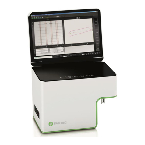
SYSMEX CyFlow Ploidy Analyser User manual

Sysmex Partec GmbH
Am Flugplatz 13, 02828 Görlitz, Germany · Phone +49 3581 8746-0 · Fax +49 3581 8746-70 · [email protected] · www.sysmex-partec.com
CyFlow® Ploidy Analyser
Instrument Operating Manual
Revision:
Rev-03_2014-10-22
Issued by:
Sysmex Partec GmbH

Instrument Operating Manual CyFlow® Ploidy Analyser Rev-03_2104-10-22
Sysmex Partec GmbH
Am Flugplatz 13, 02828 Görlitz, Germany · Phone +49 3581 8746-0 · Fax +49 3581 8746-70 · [email protected] · www.sysmex-partec.com 2 / 47
Imprint
Copyright 2014 by
Sysmex Partec GmbH
Am Flugplatz 13
02828 Görlitz
Germany
Phone: +49 (0) 3581 8746 0
Fax: +49 (0) 3581 8746 70
Mail: support@sysmex-partec.com
Web: www.sysmex-partec.com

Instrument Operating Manual CyFlow® Ploidy Analyser Rev-03_2104-10-22
Sysmex Partec GmbH
Am Flugplatz 13, 02828 Görlitz, Germany · Phone +49 3581 8746-0 · Fax +49 3581 8746-70 · [email protected] · www.sysmex-partec.com 3 / 47
Table of content
Table of content................................................................................................................3
1. Introduction..........................................................................................................5
2. Presentation.........................................................................................................6
2.1 Basics ..........................................................................................................6
What are topics covered by this manual?...................................................................6
What other manuals are available?............................................................................6
What should I know before operating the CyFlow®Ploidy Analyser? .........................6
2.2 Introduction to Flow Cytometry ......................................................................7
2.3 Flow Cuvette and Light Signals......................................................................7
2.4 Optical Standard Setup –Parameters and Filters..........................................8
2.5 In flow cytometry, what is.............................................................................10
… a parameter? .......................................................................................................10
… a histogram channel?..........................................................................................10
… the count in a histogram? ....................................................................................10
… a peak? ........................................................................................................10
… background in a histogram? ................................................................................10
3. Instrument starting procedure.............................................................................11
3.1 Sheath fluid level control and/or refill ...........................................................11
3.2 Switching on the CyFlow®Ploidy Analyser...................................................11
3.3 User levels...................................................................................................13
4. CyViewTM Controls .............................................................................................14
4.1 CyView™ Instrument Setting Controls .........................................................15
4.1.1 1D/2D PLOTS–display options.......................................................15
4.1.2 RESULTS .......................................................................................16
4.1.3 REGIONS .......................................................................................17
4.1.4 GENERAL - properties of the instrument.........................................18
4.1.5 ACQUISITION –instrument control.................................................18
4.1.6 MEASURE –definition of measure modes......................................19
4.1.7 Measure modes ..............................................................................20
5. CyViewTM Instrument/Measurement Settings......................................................23
5.1 Priming / Initialization process......................................................................23
5.2 Work process...............................................................................................25
5.3 Shut down process......................................................................................25
5.4 Intermediate cleaning process.....................................................................26
5.5 Sheath and Waste bottle..............................................................................27
6. Measurement parameters ..................................................................................27

Instrument Operating Manual CyFlow® Ploidy Analyser Rev-03_2104-10-22
Sysmex Partec GmbH
Am Flugplatz 13, 02828 Görlitz, Germany · Phone +49 3581 8746-0 · Fax +49 3581 8746-70 · [email protected] · www.sysmex-partec.com 4 / 47
6.1Instrument setting properties........................................................................27
6.1.1 Threshold settings (T) .....................................................................27
6.1.2 Flow speed (S)................................................................................27
6.1.3 Light source (L)...............................................................................28
6.2 1D/2D Plot properties...................................................................................28
6.3Region/ROI properties.................................................................................29
6.4 Compensation .............................................................................................31
7A Typical Sample Analysis ....................................................................................32
8Automatic Peak Analysis.......................................................................................34
8.1MAIN USER/USER Mode............................................................................34
8.2 SERVICE/ADMINISTRATOR Mode.............................................................36
8.3 Export of Peak Analysis and 1-parameter histograms..................................37
9Keyboard/Mouse combinations .............................................................................39
10 Appendix............................................................................................................40
10.1 Biohazards......................................................................................................40
10.2 Maintenance...................................................................................................41
10.2.3 Service 41
10.2.4 Transport and Storage.................................................................................42
10.2.5 Disposal.......................................................................................................42
10.3 Laser Safety....................................................................................................43
10.4 Technical Specifications..................................................................................44
10.4.3 Optical Standard Setup................................................................................44
10.4.4 CyFlow®Ploidy Analyser System.................................................................44
10.4.5 CyFlow®Ploidy Analyser Optics...................................................................45
10.4.6 CyFlow®Ploidy Analyser Fluidics.................................................................45
11 Notes .................................................................................................................46

Instrument Operating Manual CyFlow® Ploidy Analyser Rev-03_2104-10-22
Sysmex Partec GmbH
Am Flugplatz 13, 02828 Görlitz, Germany · Phone +49 3581 8746-0 · Fax +49 3581 8746-70 · [email protected] · www.sysmex-partec.com 5 / 47
1. Introduction
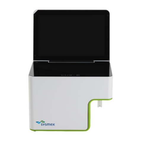
The CyFlow®Ploidy Analyser is a compact Flow Cytometry (FCM) system produced by
Sysmex Partec GmbH, Germany. It is designed to analyze the DNA content of intact plant
and animal nuclei and of micro-organisms by fluorescence labeling of DNA by
fluorochromes, propidium iodide (PI) or 4',6-diamidino-2-phenylindole (DAPI).
CyView™for Ploidy Analyser is the instrument operation software of the CyFlow®Ploidy
Analyser. Sysmex Partec is continuously working on CyView™to better fulfil your
demands. If you have questions concerning this manual or the software, find problems
associated with CyView™or you have a good suggestion to be included in a new version,
please let us know by sending an email or a note to Sysmex Partec GmbH.
The present manual is valid as of CyView™ software versions 1.5.
For more details about reagent kits, suitable for use with the CyFlow®Ploidy Analyser,
please refer to the product list in the chapter Technical Specifications and the respective
product data sheets which can be requested by e-mail at Partec Support
service@partec.com. There are also several Application Notes available.
If you have questions, please contact your local distributor, one of the Partec subsidiaries,
or Partec in Germany (service@sysmex-partec.com).
Further details and addresses can be found on our website at:
www.sysmex-partec.com
Please do not forget to add in your request the following information:
Serial number (serial No.) of the CyFlow® Ploidy Analyser
Your complete contact address
This manual contains references to names and products from Partec and other companies which are
registered trademarks or protected by copyright.
Partec GmbH, CyFlow®Ploidy Analyser, CyView™ for Ploidy Analyser, Robby®.
Microsoft®Corp.: Windows, Word, Excel, PowerPoint, Paint.
Hewlett Packard®: Deskjet Laserjet.

Instrument Operating Manual CyFlow® Ploidy Analyser Rev-03_2104-10-22
Sysmex Partec GmbH
Am Flugplatz 13, 02828 Görlitz, Germany · Phone +49 3581 8746-0 · Fax +49 3581 8746-70 · [email protected] · www.sysmex-partec.com 6 / 47
2. Presentation
2.1 Basics
The CyFlow®Ploidy Analyser is available in three versions:
Order No. 11-01-1002
Sysmex Partec CyFlow®Ploidy Analyser “DAPI” one parameter (FL) | UV LED excitation
Order No. 11-01-1003
Sysmex Partec CyFlow®Ploidy Analyser “PI” two parameters (SSC/FL) | green 532nm
laser
Order No. 11-01-1004
Sysmex Partec CyFlow®Ploidy Analyser “DAPI/PI” two parameters (SSC/FL) | green
532nm laser and UV LED excitation
The CyFlow®Ploidy Analyser is equipped with a UV-LED - 365 nm emission wavelength
(11-01-1002) and/or a Nd-YAG green solid state laser - 532 nm emission line (11-01-1003
and 11-01-1004, respectively). For fluorescence detection of DAPI (DAPI-DNA) a
sensitive blue PMT is used which analyses fluorescent light between 435 nm and 560 nm.
The same detector is used to monitor 532 nm side scattered light from Nd-YAG laser
excitation. Propidium iodide fluorescence (PI-DNA) is detected by a red-sensitive PMT at
fluorescence wavelengths above 590 nm.
What are topics covered by this manual?
The CyFlow®Ploidy Analyser Instrument Operating Manual covers the operation and
maintenance of the CyFlow®Ploidy Analyser. This manual also covers details related to
the CyView™ software.
What other manuals are available?
Application Notes, reagent kit data sheets and a Service Manual are available on request
at Sysmex Partec GmbH. They contain hints to achieve the best results.
What should I know before operating the CyFlow®Ploidy Analyser?
This manual assumes that you have basic knowledge on flow cytometry. In the best case
a well experienced "flower" is around - so let her/him help you. Basic books are available
about flow cytometry which may help you as well (e.g. Howard M. Shapiro, Practical Flow
Cytometry. Wiley 2002).

Instrument Operating Manual CyFlow® Ploidy Analyser Rev-03_2104-10-22
Sysmex Partec GmbH
Am Flugplatz 13, 02828 Görlitz, Germany · Phone +49 3581 8746-0 · Fax +49 3581 8746-70 · [email protected] · www.sysmex-partec.com 7 / 47
2.2 Introduction to Flow Cytometry
The term Flow Cytometry describes a technique for the analysis of cells –or particles –in
aqueous suspension. Cells or other biological particles pass in a single cell stream
through a measuring apparatus. In the most common scenario, one or more lasers
interrogate each particle and, at a minimum, the system measures the degree and
direction of scattered light –indicators of the particle’s size, shape and structure. If
particles have been stained with one or more fluorescent dyes –known as fluorochromes
–the light source excites these dyes to provide additional biological information about
each particle, such as the presence of specific cellular compounds. The unique
advantage of Flow Cytometry is that it can rapidly and quantitatively measure multiple
simultaneous parameters on individual live cells.
2.3 Flow Cuvette and Light Signals
Flow Cuvette
The main element of the CyFlow®Ploidy Analyser Flow Cytometer is a flow
cuvette. This is made of quartz glass which contains a capillary with a diameter of
200 x 350 µm.
Fluidics
The fluid system of a flow cytometer is used to transport particles from a random
three dimensional sample suspension to an orderly stream of particles travelling
past one or more illuminating beams. The fluidic system uses air pressure
regulation to ensure stable operation and consists of a sheath fluid line and a
sample line feeding into the flow cell. As the sample enters the flow cell chamber,
the outer, sheath fluid flow hydro-dynamically focuses the sample flow into a
narrow core region within the jet and presents a single file of particles to excitation
sources. This geometry provides increased positioning accuracy at the laser
interrogation point for consistent excitation irradiance and greatly reduced particle
blockage of the flow cell.

Instrument Operating Manual CyFlow® Ploidy Analyser Rev-03_2104-10-22
Sysmex Partec GmbH
Am Flugplatz 13, 02828 Görlitz, Germany · Phone +49 3581 8746-0 · Fax +49 3581 8746-70 · [email protected] · www.sysmex-partec.com 8 / 47
Scatter Signals
In the CyFlow®Ploidy Analyser 11-01-1003 and 11-01-1004 cells pass in a
single file through the Nd-YAG laser beam focused into the capillary. This causes
scattering of light providing information about different cellular characteristics. The
side scattered light (side scatter, SSC) is emitted in an angle of about 90° and
provides information about the “granularity”or refraction properties of the particles
or cells. Particles/Cells with a high granularity/refraction create a strong signal in
the SSC.
Fluorescence Signals
Fluorescence occurs when a molecule excited by light of one wavelength returns
to a lower energy state by emitting light of a longer wavelength. Cell nuclei can be
stochiometrical labelled by fluorescent probes and fluorescence emission after
sufficient excitation can be correlated to DNA content.
2.4 Optical Standard Setup –Parameters and Filters
The CyFlow® Ploidy Analyser is equipped with one (11-01-1002) or two (11-01-
1003/11-01-1004) optical parameters for the detection of DAPI fluorescence (11-01-1002)
and/or Propidium Iodide fluorescence and side scattered light (11-01-1003/1004). The
fluorescence and side scattered light is collected by a microscope lens in an angle of 90°.
The light is subdivided into two different wavelength bands by optical filter glasses.
Signal processing with Photomultiplier Tubes (PMT)
Photomultiplier tubes (PMT) collect fluorescence or scatter light signals, which
generate an electronic pulse inside the PMT. The pulse amplitude is proportional
to the number of incoming photons. Following linear or logarithmic amplification,
the signals are converted into electronic signals by an Analog/Digital-Converter
(ADC). As a particle of interest passes the focus, its fluorescence is detected by
the PMT, and an electronic pulse is generated. The acquisition of a signal is
triggered when the signal amplitude exceeds a predefined threshold level. The
threshold is primarily used to reject events such as debris particles or noise from
optical and electronic sources.
Optical filtration
Optical filters transmit a specific wavelength band of the visible light and block
other wavelengths. Optical filtration is used to adapt the wavelength reaching the
optical detector to the emission wavelengths of the used fluorochrome.

Instrument Operating Manual CyFlow® Ploidy Analyser Rev-03_2104-10-22
Sysmex Partec GmbH
Am Flugplatz 13, 02828 Görlitz, Germany · Phone +49 3581 8746-0 · Fax +49 3581 8746-70 · [email protected] · www.sysmex-partec.com 9 / 47
Display of a measurement
The flow cytometric data can be displayed either as a 1-parameter histogram (left
plot next page) or as a 2-parameter dot plot (right plot next page). A 1- parameter
histogram displays the distribution of cells among a specific property, e.g. how
many cells contain a given quantity of DNA. A 2-parameter dot plot presents
correlated data over 2 dimensions. In the CyFlow®Ploidy Analyser with 532 Nd-
YAG lasers it displays DNA content versus side scatter signal (correlated to
particles size and refraction properties, right plot next page).
The CyFlow®Ploidy Analyser with UV-LED displays one single 1-parameter
histogram (left figure). The instrument with 532 nm laser displays both, 1
parameter histogram for DNA quantity and a 2 P-dot plot for DNA quantity versus
side scatter property (right figure).
Gain
The gain is the value of the PMT amplification applied to a signal.
Regions and Gates
Regions are drawn to define a certain cell or particle population. In the 1-
parameter histogram this is done by setting a Histogram Region (see Reg1, Reg2,
Reg3 and Reg4, figure above), within the 2-parameter dot plot a Polygonal Region
is used. A gate is a region applied on a second plot as a data window. A gated plot
displays only those data defined by the gating region.
Fluorescence staining
For the characterization of DNA content cell nuclei are marked with a specific
fluorescent stain. DAPI based reagent protocols like CyStain UV, CyStain Ploidy
or CyStain precise label the double-stranded DNA at A-T base-pairs. The DNA
fluorochrome DAPI is optimally excited by the UV-LED at 365 nm and blue and
green fluorescence is emitted (11-01-1002/1004).
Propidium iodide, a DNA fluorochrome, which is used in Sysmex Partec CyStain
absolute P and T reagent kits, intercalates into the double-stranded DNA and is
excited by green light (Nd-YAG laser). Propidium iodide emits orange and red

Instrument Operating Manual CyFlow® Ploidy Analyser Rev-03_2104-10-22
Sysmex Partec GmbH
Am Flugplatz 13, 02828 Görlitz, Germany · Phone +49 3581 8746-0 · Fax +49 3581 8746-70 · [email protected] · www.sysmex-partec.com 10 / 47
fluorescence. In the CyFlow®Ploidy Analyser the relevant fluorescence signals
are collected in the DNA-DAPI channel and the DNA-PI channel, respectively.
Next to the fluorescence scattered light is detected in the SSC channel only of
CyFlow®Ploidy Analysers equipped with a Nd-YAG solid state laser.
A list of dedicated Sysmex Partec reagent kits is contained in the Technical
Specification section of the Appendix of this manual.
2.5 In Flow Cytometry, what is...
… a parameter?
In flow cytometry, parameter denotes a measured property of the particles. Frequently, a
parameter is synonymous to an optical channel. E.g. an instrument with 2 parameters is
equipped with 2 optical detectors.
…a histogram channel?
The measured signal intensity is assigned to one of 65536 quantity classes or channels.
In a one-parameter histogram the channels are represented on the x-axis.
… the count in a histogram?
The number of cells being assigned to a given channel is referred to as channel content
or simply count. In a one-parameter histogram, the count is shown on the y-axis.
… a peak?
All cells having about equal characteristics among the analysed cell property (e.g. content
of a specific constituent like DNA), form a peak. In the case a of typical DNA histogram
one peak represents the G1 and another peak (with twice the channel value) represents
the G2/M phase of the cell cycle.
… background in a histogram?
Histograms sometimes show undesired signals in the lower channels, frequently called
´noise´ or ´background´. These signals may originate from cell or nuclei fragments or
other particles resulting from sample preparation. In case of high signal amplification,
background can also be caused by particle contaminated sheath fluid.
…the lower level (L-L) or threshold?
The lower level (L-L) threshold is a mean to suppress background signals. Signals below
the lower level are rejected from the signal acquisition. To exclude noise from a histogram
already acquired, a region-gate can be used.

Instrument Operating Manual CyFlow® Ploidy Analyser Rev-03_2104-10-22
Sysmex Partec GmbH
Am Flugplatz 13, 02828 Görlitz, Germany · Phone +49 3581 8746-0 · Fax +49 3581 8746-70 · [email protected] · www.sysmex-partec.com 11 / 47
3. Instrument starting procedure
3.1 Sheath fluid level control and/or refill
Before switching on the machine, it is recommended to
check the levels of the sheath fluid and waste bottles.
They can be found at the back-left of the apparatus in a
sliding compartment.
Make sure SHEATH bottle is filled with 700 ml of clean,
filtered, and degassed sheath fluid and is closed with
the screw top.
Please notice: Higher level of sheath fluid could lead to
unstable sample flow.
In order to guarantee highest quality of the
measurements we highly recommend use Sysmex Partec Sheath Fluid (order no. 04-
4007).
It is recommended to replace the sheath fluid at least once a week or before any daily
use.
When filling up the sheath fluid bottle make sure no air bubbles are trapped in the yellow
filter unit inside the bottle!
Make sure that the WASTE bottle is empty and the screw top is tightly closed.
The waste bottle must be emptied after and before each user session. When using bio-
hazardous samples, a volume of 50 ml of hypochlorite 0.5% (Order No 04-4012) should
be introduce into the empty waste bottle for initial disinfection.
3.2 Switching on the CyFlow®Ploidy Analyser
The power supply switch is found at the back of the Ploidy Analyser next to the main
supply cable. The Ploidy Analyser is, in default, set in a stand-by mode. The full activation
of the Ploidy Analyser requires pressing lightly the on/off tactile button on the top of the
machine. The display screen must be first lift up to access it.
This will start the embedded computer, automatically start the CyView™software and load
the last employed configuration.
On/Standby
Casual/medium expertise user:
Once the Ploidy Analyser started no
further steps are necessary. You can
directly start your measurements!

Instrument Operating Manual CyFlow® Ploidy Analyser Rev-03_2104-10-22
Sysmex Partec GmbH
Am Flugplatz 13, 02828 Görlitz, Germany · Phone +49 3581 8746-0 · Fax +49 3581 8746-70 · [email protected] · www.sysmex-partec.com 12 / 47
Lost your login details?
Important: On each new instrument a Main
User login is already established
Login: USER (case sensitive)
Password: Cube1 (case sensitive)
Login as a standard USER:
The code will be given to you by the main
user(s) of the instrument. The main user
has the rights to define or delete users.
Main CyView™login window
The log in window allows to start the software at the USER, MAIN USER or SERVICE level.
During start of the instrument the automated self-testing procedures are processed:
Cleaning up and XML-configuration:displays the
correct loading of the setting files
Searching Device: display of the correct
recognition of the connection between the
computer and the embedded electronics
Please verify that all operations are confirmed by
a green tick.

Instrument Operating Manual CyFlow® Ploidy Analyser Rev-03_2104-10-22
Sysmex Partec GmbH
Am Flugplatz 13, 02828 Görlitz, Germany · Phone +49 3581 8746-0 · Fax +49 3581 8746-70 · [email protected] · www.sysmex-partec.com 13 / 47
3.3 User levels
Three different user levels exist:
SERVICE/ADMINSTRATOR:
Restricted to authorized Sysmex Partec trained persons and for service purposes
only
MAIN USER:
Complete functionality of the instrument, method development
Main users can create new accounts of the Main User and User level
USER:
Applying standardized methods only
Users cannot create new accounts.
As a main user in order to create new accounts type in your Login name and password
and select “User Administration”.
To create a new MAIN USER account type in name and password and activate “Main
user” followed by “Build new account”.
To create a new USER account type in name and password followed by “Build new
account”. (Main user should be deactivated).
As User the own password can be changed by selecting the name and placing a new
password followed by “Change my password”.
As Main User the own password can be changed by selecting the name and placing a
new password followed by “Change my password”. As Main User any user account can
be deleted by selecting the name followed by “Delete this account”. The Main User does
not require the respective password to delete any user account.
The default user account (Name: USER; Password: Cube1) can be deleted when logged
in as Main User. Please make sure at least one Main User remains in the user list in order
to guarantee complete functionality of the software.
To enter the CyView™software from the user administration level select “Back to login”,
login with your personal Login name followed by “Work with CyView™.

Instrument Operating Manual CyFlow® Ploidy Analyser Rev-03_2104-10-22
Sysmex Partec GmbH
Am Flugplatz 13, 02828 Görlitz, Germany · Phone +49 3581 8746-0 · Fax +49 3581 8746-70 · [email protected] · www.sysmex-partec.com 14 / 47
4. CyViewTM Controls
CyView™Main Page –after successful log-in
The main window will be your interface to acquire, save, re-load and analyse your
data
Instrument real time display of workload (L), on-board memory status (M), analysis volume (V)
and analysis duration (D).

Instrument Operating Manual CyFlow® Ploidy Analyser Rev-03_2104-10-22
Sysmex Partec GmbH
Am Flugplatz 13, 02828 Görlitz, Germany · Phone +49 3581 8746-0 · Fax +49 3581 8746-70 · [email protected] · www.sysmex-partec.com 15 / 47
4.1 CyView™Instrument Setting Controls
Overview of instrument settings
4.1.1 1D/2D PLOTS–display options
The 1D/2D Plots register defines properties of the graphical plots. The basic layout in
terms of number of plots, type of plots (histograms, dot plots) and position of the plots is
defined in the used Configuration File.
As example: 12Pl →6 histograms + 6 dot plots
Plots are named H1 –Hx for histograms and P1 –Px for dot plots. A specific plot is
selected with the arrow keys.
Define a Comment characterizing the plot e.g. FSC
Select X-axis channel and Y-axis channel in dot plots or X-
axis channel only for histograms
Switch between Lin and Log scale for
Xand Yaxis and change the Zaxis (scaling)
Define an Erosion level for dots to be displayed (z-axis
level), e.g. an Erosion level of 2 shows only dots
representing 3 and more signals
Select dot plot (DP)-Mode
(Color Mode, Contour Mode or Color + Contour Mode)
Select histogram resolution as BitRange,
(values 16bit to 12bit)
Select CR –Mode to show “All events” or “Regions only”
Confirm all modifications by pressing Accept

Instrument Operating Manual CyFlow® Ploidy Analyser Rev-03_2104-10-22
Sysmex Partec GmbH
Am Flugplatz 13, 02828 Görlitz, Germany · Phone +49 3581 8746-0 · Fax +49 3581 8746-70 · [email protected] · www.sysmex-partec.com 16 / 47
4.1.2 RESULTS
The RESULTS register defines properties of calculated results displayed in the RESULTS
table.
Properties of result calculations
It is possible to set up calculations with the COUNT of individual regions according to the
specified formula:
NumReg1 (+ - x / ) NumReg2
--------------------------------------------------x Scale
DenomReg1 (+ - x / ) DenomReg2
NumRegion1/2 defines numerators
DenomRegion1/2 defines denominators
NumOperator defines operator between 2
numerators „+“, „-“, „x“ or „/“
DenomOperator defines operator between 2
denominators „+“, „-“, „x“ or „/“
Unit allows to add text to the result table
Scale introduces a factor to the formula
Counter results on refers to the result of a
Volumetric counting
Create a result by pressing “New” or delete a
result by pressing “Delete”
Confirm all modifications by pressing Accept
Result will be display in the “Results table” next to the “Region statistics”

Instrument Operating Manual CyFlow® Ploidy Analyser Rev-03_2104-10-22
Sysmex Partec GmbH
Am Flugplatz 13, 02828 Görlitz, Germany · Phone +49 3581 8746-0 · Fax +49 3581 8746-70 · [email protected] · www.sysmex-partec.com 17 / 47
4.1.3 REGIONS
Home Plot Name defines the plot the
region refers to
Color RGB defines the region´s color
and its color in color gating
Max Count defines a maximum count for
an “Cells in Region” particle limit
Sorter Region On activates region as
sorter region (only in CyFlow®Cube Sorter)
Color Gating On activates/deactivates
the region
Use Delete and New to delete and
create new regions
Use arrow keys to switch between regions
Confirm all modifications by pressing
Accept

Instrument Operating Manual CyFlow® Ploidy Analyser Rev-03_2104-10-22
Sysmex Partec GmbH
Am Flugplatz 13, 02828 Görlitz, Germany · Phone +49 3581 8746-0 · Fax +49 3581 8746-70 · [email protected] · www.sysmex-partec.com 18 / 47
4.1.4 GENERAL - properties of the instrument
The active Configuration File
The instruments Serial Number
Total Operating Time of the instrument
Measure Number shows total number of measure-
ments
Version of the instrument
Modification of the instrument
Activates Sorter function
Activates Lowpasses
Defines a factor for sample Dilution
Clinic/Customer display specific user information
Defines sample port electrode Volume in µl
µlPerSec/mBar defines a sheath fluid flow parameter
SW-Version specifies current software version
Rescale LSB shows area of automatic scaling
Storemode defines FCS file format
4.1.5 ACQUISITION –instrument control
Select the trigger parameter
Trigger Parameter should be always “DNA”
GAINS of the individual optical parameters
(0 volt - 999 volts) defines PMT
signal amplification
Thresholds defines the trigger
signals cut-off level
(should be at least 0.1)
Flow defines the speed of sample injection in
µl/s (for regular analysis between 0.2 and 4 µl/s)
Lights on switches light sources on / off

Instrument Operating Manual CyFlow® Ploidy Analyser Rev-03_2104-10-22
Sysmex Partec GmbH
Am Flugplatz 13, 02828 Görlitz, Germany · Phone +49 3581 8746-0 · Fax +49 3581 8746-70 · [email protected] · www.sysmex-partec.com 19 / 47
4.1.6 MEASURE –definition of measure modes
Measmode allows selection of:
Analyze all:
run sample until its levels reached the stop electrode
Volumetric counting (VC) with volume
a volume can be pre-selected
Volumetric counting (VC) with electrodes:
START and STOP electrodes of the sample port
were are used to define a fixed sample volume of
200µl
Cells in region
a particle number can be pre-selected
Speed values and Volume values can be edited and will be stored upon saving a
configuration file.
Autoflags allows activation of specific functions:
Autostart: automatic start of the measurement
Activate the AutoStart flag
Press start (only once to confirm the process)
Connect a sample tube
Autostart:
With each new sample tube the next measurement will be started until the STOP button is
pressed.
AutoPA:
Automatic peak analysis, at the end of the measurement → only if an automatic Peak
Analysis is pre-selected
Autosave:
Automatic storage at the end of the measurement. Autosave does not function when the
measurement is finished by the “end” button.

Instrument Operating Manual CyFlow® Ploidy Analyser Rev-03_2104-10-22
Sysmex Partec GmbH
Am Flugplatz 13, 02828 Görlitz, Germany · Phone +49 3581 8746-0 · Fax +49 3581 8746-70 · [email protected] · www.sysmex-partec.com 20 / 47
Schematic overview of the acquisition process for all measure modes
Green and red colored bars refer to particle count indicator of CyView.
Please note: In the measure mode “VC of Volume” or “Cells in Regions” there is no cleaning
cycle. Subsequently the data can be stored. In the measure modes “VC electrodes” and “Analyze
all” the cleaning cycle will occur automatically as soon as the sample is finished.
No cleaning cycle will be started if the measurement is terminated by the “end” button.
Beware: for all measure modes the sample analysis automatically stops when the sample is empty
(the stop electrode is reached) even if the selected end criterion is not yet realized.
4.1.7 Measure modes
The following measure modes can be selected prior to start of an analysis:
Analyze all
Volumetric counting (VC) of volume
Volumetric counting (VC) electrodes
Cells in region
Other manuals for CyFlow Ploidy Analyser
1
Table of contents
Other SYSMEX Measuring Instrument manuals

SYSMEX
SYSMEX CyFlow Cube 6 V2m User manual

SYSMEX
SYSMEX BK265455 User manual

SYSMEX
SYSMEX SF-3000 User manual

SYSMEX
SYSMEX CyStain VitalCount User manual

SYSMEX
SYSMEX CyFlow Ploidy Analyser User manual

SYSMEX
SYSMEX XE-5000 User manual

SYSMEX
SYSMEX pocH-100i User manual

SYSMEX
SYSMEX CyFlow Space User manual

SYSMEX
SYSMEX XW-100 User manual

SYSMEX
SYSMEX XW-100 Manual