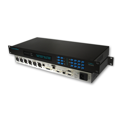
SystemBase C510xr User manual

Page 1
SystemBase
ISDN CODECS
USER MANUAL
C510xr-C520xr
REL206 upwards

Page 2
Table f C ntents
INTRODUCTION................................3
Key Features................................3
INSTALLATION.................................4
CONTROLS AND INDICATORS.......4
VFD Display .................................4
VU Meters.....................................4
Menu Buttons...............................4
DIAL Button .................................4
Keypad Dial..................................4
Patch Dial.....................................5
ANG Button................................5
Numerical 0 - 9 Buttons................5
FRONT & REAR PANELS.................6
MENU MAP.......................................7
MENU SYSTEM.................................8
Unit Description / Title...................8
ISDN Status..................................8
ISDN Caller Identification..............8
Clearing Cause.............................8
Audio Status.................................8
Select Patch.................................8
Modify Patch.................................9
Patch Name...................................9
ISDN Options...............................9
ISDN Audio Options...............9
ISDN Audio Format..........9
Audio Mixing....................9
Audio Priority....................9
Auto unt........................10
G711 Receive..................10
ISDN Channel 1 to 4 Options
...............................................10
ISDN Remote Address....10
ISDN Remote Sub-Address
.........................................10
ISDN Local Sub-Address 10
X21 Audio...................................11
Backup Options..........................11
Backup Monitor..........................11
Backup Threshold.......................11
Restore Time...............................11
Reserve Dial................................11
Audio Source..............................11
Codec Function...........................11
ISDN Mode.................................11
X21 Mode...................................11
Backup Master / Slave................11
Nailed ISDN...............................12
Auxiliary Data Port.....................12
Alarm..........................................12
eadroom...................................12
System Options..........................12
Country Options..........................12
ISDN Network.............................12
ISDN SPID C 1 to 4..................13
Password....................................13
Loopback....................................13
SNMP.........................................13
Ethernet Options.........................13
Ethernet D CP...........................13
IP Address...................................13
Ethernet Mask.............................13
Ethernet Gateway........................13
....................................................13
Set Defaults................................14
Screen Saver..............................14
Email Alert Messages.................14
Email Timing..............................14
WEB SERVER.................................15
EASYMON NETWORK MONITOR..16
REMOTE MANAGEMENT...............17
PHYSICAL CONNECTIONS............18
Analogue Audio..........................18
Digital Audio................................18
LAN Port.....................................18
ISDN Ports..................................18
X.21 Port.....................................18
Manager Input Port.....................19
Manager Output Port..................19
Auxiliary Data Port......................19
Alarm Signal...............................19
Remote Trigger...........................19
PHYSICAL PROPERTIES...............20
Dimensions.................................20
Power Requirements..................20
Environmental Conditions...........20
WARRANTY INFORMATION ........20
CE COMPLIANCE ..........................20
EXPORT REGULATIONS (EAR) ...20
Page 3
INTRODUCTION
The C510xr / C520xr Audio Codecs have been designed for the broadcast of high quality audio over digital
networks, such as ISDN, dedicated digital lines, optical fibre networks, digital microwave links and satellite
links. To achieve an efficient utilisation of the available network data bandwidth, the C510xr / C520xr can be
configured to use Dual G722, Dual G711 or apt-X100 4:1 fixed audio encoding system to provide full duplex,
point-to-point audio transmission.
Key Features
C510xr (ISDN – 2 x 64Kbps, X.21-384Kbps )
C520xr (ISDN – 4 x 64Kbps, X.21-384Kbps )
32 Bit Floating Point DSP – Analog Device S ARC Processor
Internet Web-Server for Remote Management and Diagnostics
X.21 Connectivity 64Kbps to 384Kbps
ISDN Connectivity 64Kbps to 256Kbps
APT-X Encoding & Decoding - 3.7k z to 22.7k z Stereo Audio (64 - 384Kbps)
Dual G722 Encoding & Decoding – 7.5k z Mono (64Kbps)
Dual G711 Encoding & Decoding – Telephone Calls ( igh Quality Digital ybrid)
Automatic ISDN Backup & Restore
Analogue and Digital AES3 Audio Interface via XLR Connectors
Simultaneous Input & Output VU Meter Display
Automatic Email Alerts – Alarm/Diagnostics Information
Compact Design - 1U 19” Rackmount Unit
Backward Compatible with C310xr, C400xr & C450xr Codecs
Selectable Analogue Audio eadroom
SNMP Management
Dual, End-to-End, Duplex, Contact closures
C510xr is upgradable to the C510ip

INSTALLATION
All Systembase C500 series codecs are designed to
fit a standard 19” rack. Each unit measures
44.45mm high (1U). Notes for installing:-
1/ Do not obstruct any air vents that the product may
have.
2/ Do not mount the unit directly above or below
other equipment within the rack. It is recommended
to leave a space of 1U between units.
3/ Where possible connect the M4 earth bonding
point to the rack enclosure frame.
CONTROLS AND INDICATORS
VFD Display
A 24 character by 2 line VFD (Vacuum Fluorescent
Display), provides comprehensive information on
the configuration of the unit and current status.
VU Meters
20 bit True RMS Digital VU Meters for monitoring
Left and Right audio channels with Peak old. The
VU Meter range is -60dB to 0dB with red LEDS to
indicate clip.
Menu Butt ns
Menu Scroll Up / Previous button.
Menu Scroll Down / Next button.
Menu Select / Edit button is used to select the
configuration which is to be modified.
Menu Backspace button.
NO NO / Cancel button is used to answer No or
to abort the configuration change. The NO button is
also used to exit a menu level and return to the level
above. Pressing the NO button several times will
always take the user back to the Title display.
YES YES / Confirm button is used to answer
YES or to confirm the configuration change.
DIAL Butt n
The DIAL button is used to dial the ISDN call(s).
Keypad Dial
The first depression of the DIAL button will take the
unit into the Keypad Dial menu as the first option.
This allows the user to type in an ISDN number via
the keypad.
MENU : Keypad Dial (Num)
01256880123
An optional sub-address can also be specified by
use of the button.
MENU : Keypad Dial (Sub)
1
Once the ISDN number has been entered, a second
depression of the DIAL button instructs the unit to
dial the displayed ISDN number. The call status is
then displayed as follows:
INFO: ISDN S a us
Ready Ready Ready Ready
INFO: ISDN S a us
Dial Ready Ready Ready
If the call has successfully connected then the
following is displayed:
INFO: ISDN S a us
Con Ready Ready Ready
If the call fails to be established, you may press the
button twice to access the disconnection cause
value. The and buttons maybe used to
access information about the adjacent ISDN
channels.
INFO: CH1 CLEARING CAUSE
ISDN No Responding
To Dial the B2, B3 and B4 Channels, repeat the
above procedure for each. The audio bandwidth will
automatically adjust to include the additional B
Channels.
If further information is required about the current
disconnection clause value you may press the
button twice.
Page 4

Note: The Keypad Dial Option will use the Audio
configurations for the currently selected patch.
Patch Dial
The first depression of the DIAL button followed
immediately by a second depression will take the
unit into the Patch Dial menu, allowing the user to
access 1 of 26 pre-stored configuration memories:
MENU : Pa ch Dial 1
PATCH 1
The and buttons can be used to select the
required patch (1 of 26). A third depression of the
DIAL button instructs the unit to dial the ISDN
numbers associated with the selected patch. The
call status is then displayed as above.
If any of the ISDN calls fail to be established, the
user can request the unit to redial the failed calls by
pressing the DIAL button twice, or by pressing the
DIAL button followed by the ISDN telephone
number.
HANG Butt n
The first depression of the HANG button is used to
hang-up the ISDN calls.
MENU :Hangup ISDN
ALL(Yes) or Bch(number)
If Yes is pressed then all ISDN calls are
disconnected. Alternatively you can enter a number
1..n to disconnect a specific ISDN Bchannel.
Numerical 0 - 9 Butt ns
The 0 - 9 Numerical Keypad allows entry of ISDN
numbers, sub-address information and for use in
patch names.
Page 5

Page 6
FRONT & REAR PANELS

MENU MAP
Page 7
TITLE
SCREEN
MODIFY
PATC
SELECT
PATC
AUDIO
STATUS
ISDN
STATUS
SYSTEM
OPTIONS
LOOP
BACK
PASSWORD
COUNTRY
OPTIONS
SET
DEFAULTS
ISDN
NETWORK
C 1
SPID
IP
ADDRESS
ET ERNET
GATEWAY
ET ERNET
MASK
ET ERNET
OPTIONS
SET
PASSWORD
BACKUP
OPTIONS
X21
AUDIO
ISDN
OPTIONS
PATC
NAME
ALARM
AUX DATA
CODEC
FUNCTION
AUDIO
SOURCE
C 3
OPTIONS
C 2
OPTIONS
C 1
OPTIONS
ISDN AUDIO
OPTIONS
C 4
OPTIONS
AUTO
UNT
AUDIO
PRIORITY
AUDIO
MIXING
ISDN AUDIO
FORMAT
G711
RECEIVE
LOC
SUB ADDR
REM
SUB ADDR
C 1
REM ADDR
LOC
SUB ADDR
REM
SUB ADDR
C 2
REM ADDR
LOC
SUB ADDR
REM
SUB ADDR
C 3
REM ADDR
LOC
SUB ADDR
REM
SUB ADDR
C 4
REM ADDR
C 4
SPID
C 3
SPID
C 2
SPID
C 4
CALLER ID
C 3
CALLER ID
C 2
CALLER ID
C 1
CALLER ID
AES
STATUS
CLEARING
CAUSE 4
CLEARING
CAUSE 3
CLEARING
CAUSE 2
CLEARING
CAUSE 1
RESTORE
TIME
BACKUP
T RES LD
BACKUP
MONITOR
RESERVE
DIAL
EADROOM
SNMP
SCREEN
SAVER
ET ERNET
D CP
UP
DOWN
RIGHT / EDIT
BACKSPACE
YES CONFIRM EDIT
NO CANCEL EDIT / LEFT

MENU SYSTEM
The menu system on the C510ip Audio Codec has
been designed to allow the user to configure the unit
with ease. Six keys are used to drive the menu
system :-
UP
DOWN
RIGHT / EDIT
BACKSPACE
YES CONFIRM EDIT
NO CANCEL EDIT / LEFT
Unit Descripti n / Title
The software release and serial number of the unit
are displayed on the Title screen.
SYSTEMBASE C520xr
REL 001 S/N 0108-001
ISDN Status
The status of the ISDN B Channels.
INFO: ISDN S a us >
Ready Ready Ready Ready
The ISDN status options are:
Load (Loading Patch)
Dorm (Dormant)
Ready (Layer 1 Activated)
Alert (Alerting)
Incom (Incoming Call Connected)
Con (Outgoing Call Connected)
Synch (Bad Line Termination)
Nail (Nailed Up Mode)
Note: If the C510xr/C520xr is configured in X.21 Mode, the
ISDN port can still function, however the audio will not be
routed through to the ISDN connector.
ISDN Caller Identificati n
The ISDN number of the last incoming caller for the
ISDN B Channels.
INFO: CH1 CALLER ID
01256880123
Clearing Cause
The Clearing Cause for each of the available ISDN
B Channels is displayed.
INFO: CH1 CLEARING CAUSE
Audi Status
The status of the received audio, the audio format
and the data rate of the codec.
INFO: Audio S a us SYNC>
APTX:7K5 Mono 64Kbps
The codec has been designed to Mute the audio
signal if end-to-end synchronisation is not achieved.
The data rate displayed is the actual data rate which
the codec has achieved end-to-end synchronisation
and not necessarily the configured mode.
The button may be used to display information
about the AES input data stream.
INFO: Aes S a us
RX=Con FMT=Pro VLD=PCM
RX is the status of the AES audio receive signal.
Con = Connected, Dis = Disconnected
FMT is the AES format.
Pro = Professional, Con = Consumer
VLD is the AES Valid Bit
PCM = PCM, Dat = Data
Select Patch
The select patch menu is used to load 1 to 26
available patch memories.
MENU: Selec Pa ch
PATCH 1
EDIT: Selec Pa ch 1
PATCH 1
Page 8

M dify Patch
The user can then modify the settings associated
with the selected patch by pressing the button.
MENU: Modify Pa ch
PATCH 1
Patch Name
MENU: Pa ch Name
PATCH 1
The button is used to edit the patch name.
EDIT: Pa ch Name
The and buttons are used to scroll through A
- Z and 0 - 9, the numerical keypad can also be
used for entry. The button confirms the character
selection and moves to the next character position.
The button backspaces to edit a character once
it has been confirmed. On completion of entry of up
to 24 characters, press the YES button to save the
changes, and the NO button to abort the changes.
MENU: Pa ch Name
LONDON STUDIO 2
ISDN Opti ns
MENU: ISDN OPTIONS
The next level of the menu system allows the user
to modify the parameters associated with ISDN
operation of the unit.
ISDN Audi Opti ns
MENU: ISDN Audio Op ions
ISDN Audi F rmat
MENU: ISDN Audio Forma
APTX: 15K2 S ereo 256Kbps
The and buttons can be used to select the
required ISDN Audio format:
APTX: 15K2 Stereo 256Kbps (C520xr)
APTX: 22K5 Mono 192Kbps (C520xr)
APTX: 12K2 Stereo 192Kbps (C520xr)
APTX: 15K2 Mono 128Kbps
APTX: 7K5 Stereo 128Kbps
APTX: 7K5 Mono 64Kbps
APTX: 3K7 Stereo 64Kbps
G722: 7K5 Dual 64Kbps
G711: 3K2 Dual 64Kbps
IT-APTX:7K5 Stereo 128K ( itachi mux)
IT-APTX:15K2 Mono 128K ( itachi mux)
The user can also change the ISDN Audio mode
dynamically while ISDN calls are connected, and
automatically add or delete ISDN B Channels as
required. The codec will take 5 seconds to respond
to any changes.
NOTE: When operating in Mono, only the Left Input and Left
Output audio channels are active if the Audio Mixing option
has been switched OFF.
Audi Mixing
MENU: ISDN Audio Mixing
On
The C510ip codec can be configured to digitally
monoise the selected audio source, by mixing the
Left and Right signals with a 6dB pad. The
monoised signal is replicated to both Analogue and
Digital AES3 Left and Right output channels.
NOTE: Audio Mixing is only active when operating on ISDN.
Audi Pri rity
MENU: ISDN Audio Priori y
Bandwid h
Page 9

If a problem occurs on the ISDN telephone
exchange, and some of the ISDN calls are
terminated, the codec will automatically drop back
and use the data bandwidth on the remaining ISDN
calls to give the best possible audio circuit. The
codec can be configured to give priority to either
Audio Bandwidth or Stereo image, when deciding
what operating mode to drop back to.
Aut Hunt
MENU: ISDN Au o Hun
Off
The C510xr/C520xr can be configured to
automatically detect the audio format of the
incoming call and re-configure its mode to match.
The re-configuration is only for the duration of the
incoming call, the codec will revert back to the
original configuration when the call is terminated. A
valid audio signal is required on the inputs to the
codec to ensure correct operation.
G711 Receive
MENU: ISDN G711 Receive
Off
The C510xr/C520xr can be configured to receive
G711 (analogue telephone) calls.
ISDN Channel 1 t 4 Opti ns
MENU: ISDN CH1 Op ions
The ISDN parameters associated with each ISDN B
Channel can be changed. The C510xr has 2 ISDN B
Channels available and the C520xr has 4 ISDN B
Channels. The following 3 option menus are
repeated for all available Channels.
ISDN Rem te Address
MENU: CH1 Rem Address
The ISDN Remote Address (telephone number) can
be entered using the numerical keypad. The
button backspaces to edit a number once it has
been confirmed. On completion of entry of up to 23
digits, press the YES button to save the changes,
and the NO button to abort the changes.
MENU: CH1 Rem Address
01256880123
ISDN Rem te Sub-Address
MENU: CH1 Rem Subaddress
The ISDN Remote Sub-Address can be entered
using the numerical keypad. The button
backspaces to edit a number once it has been
confirmed. On completion of entry of up to 6 digits,
press the YES button to save the changes, and the
NO button to abort the changes.
MENU: CH1 Rem Subaddress
1
ISDN L cal Sub-Address
MENU: CH1 Loc Subaddress
The ISDN Local Sub-Address can be entered using
the numerical keypad. The button backspaces to
edit a number once it has been confirmed. On
completion of entry of up to 6 digits, press the YES
button to save the changes, and the NO button to
abort the changes.
MENU: CH1 Loc Subaddress
2
Page 10

X21 Audi
MENU: X21 Audio
APTX: 15K2 S ereo 256Kbps
The and buttons can be used to select the
required X21 Audio format:
APTX: 22K5 Stereo 384Kbps
APTX: 15K2 Stereo 256Kbps
APTX: 22K5 Mono 192Kbps
APTX: 12K2 Stereo 192Kbps
APTX: 15K2 Mono 128Kbps
APTX: 7K5 Stereo 128Kbps
APTX: 7K5 Mono 64Kbps
APTX: 3K7 Stereo 64Kbps
NOTE: When operating in Mono, only the Left Input and Left
Output audio channels will be active if the Audio Mixing
option has been switched OFF.
Backup Opti ns
The user can modify the configurations associated
with the automatic ISDN Backup and Restore
operation.
Backup M nit r
INFO: Backup Moni or
0% X21 Sync Errors
This menu displays the percentage of Sync Loss
Errors in the last 10 seconds.
Backup Thresh ld
MENU: Backup Threshold
50% of X21 SYNC Errors
The Backup Threshold is the level at which the
automatic ISDN Backup is initiated. The Backup
Threshold can be changed to a value between 0%
and 100%.
Rest re Time
MENU: Res ore Time
10 Seconds
The Restore Time is the time of error free data
throughput required to initiate the automatic X21
Restore. The Restore Time can be changed to a
value between 0 and 60 seconds.
Reserve Dial
MENU: Reserve Dial
Off
The C510ip can be configured to automatically dial
a reserve site in the event of a total failure at the
primary site. The ISDN dialling parameters for the
reserve site are obtained from the adjacent patch to
the currently selected patch (i.e. patch+1).
This function is only active when the C510ip is
configured for Backup Master mode.
Audi S urce
MENU: Audio Source
Analog
The Audio Source can be set to Analog or AES3.
The AES3 output provides digital audio at a sample
rate of 48K z with 24 bit audio resolution.
C dec Functi n
MENU: Codec Func ion
ISDN Mode
The C510xr/C520xr Codec can operate in 1 of 5
selectable modes :-
ISDN Mode
X21 Mode
Backup Master
Backup Slave
Nailed ISDN
ISDN M de
The ISDN ports are the primary network interface
and the X.21 port is the secondary network
interface. If there are no ISDN calls connected, the
audio will be routed to the X.21 port by default.
X21 M de
The codec will only route audio to the X.21 port, and
will effectively ignore the ISDN ports. The ISDN
ports will still be capable of making and receiving
ISDN calls, however the audio will not be routed
through to the ISDN connections.
Backup Master / Slave
The X.21 port is the primary network interface and
the ISDN ports are used for backup. The codec at
Page 11

one end of the X.21 line should be configured as a
Backup Master and the other codec should be
configured as a Backup Slave. This prevents both
codecs initiating the ISDN Backup, which can cause
a call conflict. The automatic ISDN Backup is
initiated by the Backup Master Codec following 50%
of synchronisation errors on the X.21 line. The X.21
Restore occurs following 10 seconds of continuous
error free, test data transmissions on the X.21 line.
The Backup Threshold and Restore Time settings
can be modified from these factory defaults using
the Backup Options menu.
NOTE: When operating in ISDN Backup Master/Slave mode,
it is advised that the DCE should carry X.21 termination
resistors.
Nailed ISDN
Nailed ISDN lines are available in some countries
for fixed point-to-point digital Transmissions. The
DIAL and HANG buttons are not required in this
mode and are therefore disabled. The audio format
used is defined within the ISDN Options menu.
The Nailed ISDN feature supports connectivity with
itachi Ta's in the following audio modes:
IT-APTX:7K5 Stereo 128K ( itachi mux)
IT-APTX:15K2 Mono 128K ( itachi mux)
Auxiliary Data P rt
MENU: AuxDa a
Off
The Auxiliary Data Port can be configured for the
following modes:
Off,
9600bps,
4800bps,
2400bps,
9600bps(alt),
4800bps(alt),
2400bps(alt),
Relay Mode.
NOTE1: CTS output signal should be used for Flow Control
when Auxiliary Data is enabled.
NOTE2: All modes appended by “(alt)” are compatible with
codec’s manufactured by APT.
NOTE3: Relay mode enables two sets or bi-directional
contact closures. The connection details are shown in the
“Manager Input Port” and “Manager Output Port” sections of
this manual.
NOTE4: At present Aux data is not passed over IP
connections.
Alarm
MENU: Alarm
Sync Loss
The Alarm output can be configured to the following
options:
Off
Sync Loss
Backup
Headr m
MENU: Headroom
+12dBu
eadroom can be configured to either level.
System Opti ns
The user can modify the global System
configurations of the Codec.
C untry Opti ns
There are a number of ISDN parameters associated
with different countries and regions in the world.
NOTE : It is important that the ISDN line should be
disconnected from the Codec before any changes are made.
ISDN Netw rk
MENU: ISDN Ne work
Euro ETSI
The C510xr/C520xr can be re-configured to operate
on 1 of 12 International ISDN Standards:
Euro ETSI
China
New Zealand
France VN3
Australia
Japan NTT
olland
Israel
Eire
DMS100 (USA)
National 1 (USA)
Custom 5ESS (USA)
Page 12

ISDN SPID CH1 t 4
MENU: CH1 Spid Pass
001441256880123
The user can configure the ISDN SPID Codes which
are required for operation in the USA and Canada
(National 1, DMS100 & Custom 5ESS). If the SPID
is accepted by the network then Pass will be
displayed in the top right corner, if it is rejected then
Fail is displayed.
Passw rd
MENU: Password
No Se
The C510xr/C520xr has two levels of password
protection to avoid accidental re-configuration; Edit
Lock and Full Lock.
The user can view all configuration menus but is not
allowed to make any changes - the YES button is
disabled. Edit Lock enables ISDN calls to dialled
and hanged. Full Lock disables ISDN dial and hang,
however, incoming ISDN calls will be answered.
NOTE: This password if independent of the web
browser user credentials.
L pback
MENU: Loopback
Off
The C510xr/C520xr can be configured to provide an
internal digital loopback of the compressed audio
signal prior to the X.21 / ISDN interface. The
loopback function will automatically use the highest
data rate available.
NOTE : The loopback function is not available when
operating in Backup Master or Backup Slave modes.
SNMP
MENU: SNMP
Off
The C510xr/C520xr can be configured to support
SNMP Management. Please contact Systembase
Limited to request the MIB file.
Ethernet Opti ns
MENU: E herne Op ions
100BASE-TX full-duplex
The C510xr / C520xr can be remotely managed via
the Ethernet Port. The display will show:-
Inactive,
Negotiation,
100BASE-TX full-duplex,
100BASE-TX half-duplex
10BASE-TX full-duplex
10BASE-TX half-duplex
Ethernet DHCP
MENU: E herne DHCP
ON / OFF
When Dynamic ost Configuration Protocol (D CP)
is selected to ON the C510ip will request a
temporary IP Address from the IP Server and
thereby simplifying the setup process.
IP Address
MENU: E herne IP
192.168.000.002
The current Ethernet IP Address of the codec can
be configured.
Ethernet Mask
MENU: E herne MASK
255.255.255.000
The Subnet Mask associated with the Ethernet IP
address of the codec can be configured.
Ethernet Gateway
MENU: E herne GATEWAY
192.168.000.001
The Gateway associated with the Ethernet IP
address of the codec can be configured.
Page 13

Set Defaults
MENU: Se Defaul s
The codec can be re-configured back to the Factory
Defaults.
MENU: Se Defaul s
Confirm Yes/No ?
Press the YES button to confirm, and the NO button
to abort.
NOTE: All changes made to the patch configurations will be
lost and there is no Undo option.
Screen Saver
MENU: Screensaver
On
The VFD screensaver can be disabled if required.
Email Alert Messages
The codec can be configured via the Ethernet
Webserver to send an Email Alert messages
following a change in Sync/ISDN state.
In the SMTP menu enter the address of your
outgoing SMTP mail server, example.mail.com.
Alternatively you may enter the IP address if known.
If you leave this field blank then the email alerts
function will be disabled.
If the mail server requires a user name and
password then fill in the User name and Password
fields otherwise leave them blank.
Now enter the recipient email address and subject
line to complete the configuration. If you leave these
fields empty no alerts or logs will be sent.
Email Timing
Once the Email Alert has been configured correctly,
the codec will send an email Event Log 10 seconds
after a Sync Loss has occurred. The Event Log will
then be cleared and disabled for 15 minutes before
being re-enabled again.
If the codec is unable to send the email successfully,
then the Event Log will be cleared and returned to
the enabled state.
Page 14

Page 15
WEB SERVER
Firstly configure the appropriate settings for your network in the Ethernet options menu. Once configured
correctly connect the port labelled “LAN” to your router.
On your computer web browser type in the IP address of the codec (http://192.168.0.2).
A Windows Login screen will be displayed. The default Username is “admin” and the default password is
“admin”. If you wish to disable the password prompt then simply leave the password field blank.
The screen shots below shows the layout of the Webserver for the C510xr/C520xr Codec.

Page 16
EASYMON NETWORK MONITOR
EasyMON is a free network monitor tool that allows an organisation to monitor multiple codecs in a single
browser window with minimal overhead.
EasyMON is free, and maybe downloaded from the systembase website, www.systembase.com. Included in
the download are instructions that will guide you through the correct configuration.
Note: For EasyMON to function you will require firmware REL203 or later.

REMOTE MANAGEMENT
The C510xr / C520xr Codec can be configured
remotely by connecting a straight 9 Way D-Type
cable to the MGR IP port, and using the Standard
Windows Terminal Program. To configure more than
one unit at the same time, the user can connect
another straight 9 Way D-Type cable from the MGR
OP port of the first unit, to the MGR IP port of the
next unit, in a “Daisy Chain” manner. There are no
limitations on the number of codecs which can be
linked together for remote configuration purposes.
On initial connection, the Standard Windows
Terminal Program screen will be blank. The user
should then press the Enter key to clear the
command buffer.
Type “poll” followed by the serial number :-
poll 0108-001 < carriage return / enter >
0108-001>
A prompt of the actual serial number will appear on
the screen.
Type “help” for list of commands.
0108-001 >help
C510xr Network Commands, (c) Systembase
Limited
poll (8 digit serial number)
status (displays the codecs current status, /s option
for short)
set name (new patch name)
set patch (patch index)
set backup level (0..100)
set restore time (1..90)
set reserve (Off, On)
set aux (Off,
9600bps,
4800bps,
2400bps,
9600bps(alt),
4800bps(alt),
2400bps(alt),
Relay Mode)
set source (Analog, AES3)
set loopback (Off, On)
set x21 (APTX:3K7 Stereo 64Kbps,
APTX:7K5 Mono 64Kbps,
APTX:7K5 Stereo 128Kbps,
APTX:15K2 Mono 128Kbps,
APTX:12K2 Stereo 192Kbps,
APTX:22K5 Mono 192Kbps,
APTX:15K2 Stereo 256Kbps,
APTX:22K5 Stereo 384Kbps)
set password (Not Set (pin), Edit Lock (pin),
Full lock (pin))
set isdn (G711:3K2 Dual 64Kbps,
G722:7K5 Dual 64Kbps,
APTX:3K7 Stereo 64Kbps,
APTX:7K5 Mono 64Kbps,
APTX:7K5 Stereo 128Kbps,
APTX:15K2 Mono 128Kbps,
IT-APTX:7K5 Stereo 128K,
IT-APTX:15K2 Mono 128K)
set mode (ISDN Mode,
X21 Mode,
Backup Master,
Backup Slave,
Nailed ISDN)
set mixing (Off, On)
set priority (Bandwidth, Stereo Image)
set autohunt (Off, On)
set alarm (Sync Loss, Backup, Off)
dial (dials the current patch)
hang (hangs the current isdn call)
set rem add (channel) (destination number)
set rem sub (channel) (destination sub addr)
set loc sub (channel) (local sub address)
The Status command will display the following
information on the codec.
Page 17

0108-001>status
SYSTEMBASE C510xr(c)
Patch Name= Patch 1
Country= EURO ETSI
Mode= ISDN Mode
ISDN 1= Ready
ISDN 2= Ready
APTX Status= SYNC
Loopback= Off
Aux Data= Off
Alarm= Sync Loss
ISDN OPTIONS
ISDN Audio= APTX:15K2 Mono 128Kbps
ISDN Autohunt= Off
C 1 Rem Add= 1111 Rem Sub= Loc Sub=
C 2 Rem Add= 1111 Rem Sub= Loc Sub=
X21 OPTIONS
X21 Audio= APTX:22K5 Stereo 384Kbps
AUDIO OPTIONS
Audio Source= Analog
ISDN Priority= Bandwidth
ISDN Mixing= Off
BACKUP OPTIONS
Backup Level= 50
Restore Time= 10
Reserve Dial= Off
Page 18

PHYSICAL CONNECTIONS
Anal gue Audi
The audio interface presents balanced stereo XLR
inputs and outputs. The electrical characteristics of
these connections is detailed below :-
I/P Impedance >10K Ohms
I/P Level +12dBu / +18dBu Max.
I/P C nnect rs Balanced XLR Female
O/P Impedance <100 Ohms
O/P Level +12dBu / +18dBu Max.
O/P C nnect rs Balanced XLR Male
C mpressi n Rati apt-x100 4:1 Fixed
C ding Alg rithms apt-X100 Sub-band ADPCM,
G722 (Stat Mode), G711
S/N Rati >102dBm
F rmat Mono / Stereo
Bandwidth 3 z to 22.5K z
Sampling Rate 48K z
Digital Audi
The digital audio interface provides both transmit
and receive AES3 connectivity via XLR input and
output connectors. Sample rate conversion is
standard on both input and output digital audio
signal paths. This facility allows the user to connect
AES3 signal sources that are asynchronous to the
codecs network interface.
The electrical characteristics of these connections is
detailed below :-
I/P C nnect rs Balanced XLR Female
O/P C nnect rs Balanced XLR Male
C mpressi n Rati apt-x100 4:1 Fixed
C ding Alg rithms apt-X100 Sub-band ADPCM,
G722 (Stat Mode), G711
Sampling Rate 48K z
LAN P rt
1 x RJ45 Connector supporting:
100BASE-TX full-duplex
100BASE-TX half-duplex
10BASE-TX full-duplex
10BASE-TX half-duplex
ISDN P rts
C510ip 1 x RJ45 Connector
Listed below are the 12 international standards
supported.
Eur ETSI
China
New Zealand
France VN3
Australia
Japan, NTT
H lland
Israel
Eire
DMS100 (USA)
Nati nal 1 (USA)
Cust m 5ESS (USA)
X.21 P rt
The electrical characteristics and the pin out of the
connector is detailed below:-
X.21 Type Fixed DTE
X.21 Speed 64Kbps to 384Kbps
X.21 Signals C, I, TXD, RXD, CLK
X.21 C nnect r 15-way Dsub Female
PIN SIGNAL
1Protect GND
2T(a)
3C(a)
4R(a)
5I(a)
6S(a)
7N/C
8Signal GND
9T(b)
10 C(b)
11 R(b)
12 I(b)
13 S(b)
INSTALLATION NOTE: The user is advised to ensure the
DCE connector of the X.21 cable is terminated correctly.
Page 19

Manager Input P rt
Type V.24/RS232 - Fixed DCE
Speed 9600bps (8,n,1)
Signals TXD, RXD, SIG GND
C nnect r 9-way Dsub Female
PIN SIGNAL
2RXD (o/p)
3TXD (i/p)
5SIG GND
6Relay 1 COM
7Relay 1 N/O
8GND
9Opto 1 (i/p)
* Opto Input – Trigger by strapping to ground.
Manager Output P rt
Type V.24/RS232 - Fixed DTE
Speed 9600bps (8,n,1)
Signals TXD, RXD, SIG GND
C nnect r 9-way Dsub Female
PIN SIGNAL
2RXD (i/p)
3TXD (o/p)
5SIG GND
6Relay 2 COM
7Relay 2 N/O
8GND
9Opto 2 (i/p)
* Opto Input – Trigger by strapping to ground.
Auxiliary Data P rt
The RS232 terminal interface can support auxiliary
bidirectional transmission of asynchronous data
over the ISDN and X21 network.
Type V.24/RS232 - Fixed DCE
Speed 9600bps (8,n,1)
Signals TXD, RXD, CTS, S GND
C nnect r 9-way Dsub Female
PIN SIGNAL
1Alarm N/C
2AUX RXD (o/p)
3AUX TXD (i/p)
4Alarm COM
5SIG GND
6Alarm N/O
8AUX CTS (o/p)
9Remote Trigger*
NOTE: The CTS output signal should be used for Flow
Control when Auxiliary Data is enabled.
Alarm Signal
The C510xr / C520xr provides a set of alarm relay
contacts with a minimum of 0.5 second duration.
These relay contacts are provided on the auxiliary
data port connector.
For connection information, please refer to the pin-
out detail of the auxiliary data connector. The
maximum voltage is 50V.
Rem te Trigger
The Remote Trigger input operates by connecting
the Remote Trigger (Pin 9 of auxiliary data
connector) to GND and holding the connection. This
instructs the Codec to dial the ISDN using the
current selected patch configuration. To hangup the
ISDN call, disconnect the pin from GND.
The Remote Trigger can be Wire-Or connected for
multiple remote trigger access, e.g. several studios
sharing a single C510xr/C520xr unit.
Remote Trigger Input - Do Not Connect to Voltage
Outputs.
Page 20
This manual suits for next models
2
Table of contents
Other SystemBase Conference System manuals

SystemBase
SystemBase C530xr User manual

SystemBase
SystemBase C300xr User manual

SystemBase
SystemBase C450xr User manual

SystemBase
SystemBase C600ip-s User manual

SystemBase
SystemBase C510ip-s User manual

SystemBase
SystemBase sLAN/all User manual

SystemBase
SystemBase C400xr User manual

SystemBase
SystemBase C530ip-s User manual

SystemBase
SystemBase C600ip-s User manual

SystemBase
SystemBase C310xr User manual