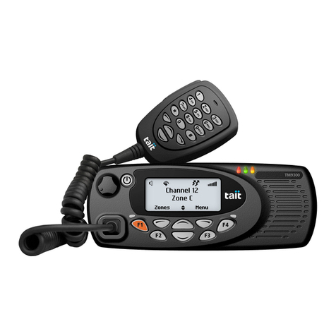
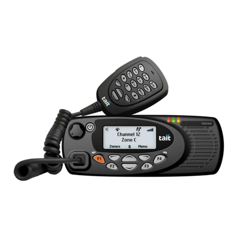
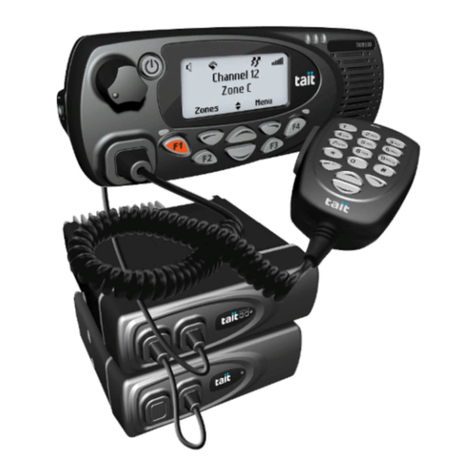
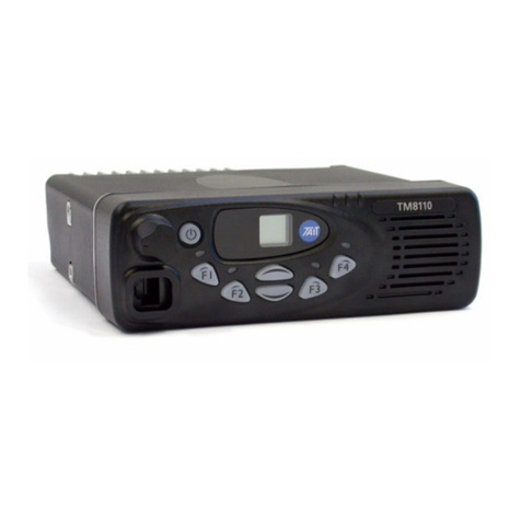
Tait TM8100 mobiles User manual

TM8000 mobiles
TM8100 Mobile Radio
Calibration Application
User’s Manual

2TM8100 Mobile Radio Calibration Application User’s Manual
August 2004 © Tait Electronics Limited
Version 2.01
August 2004 © Tait Electronics Limited

TM8100 Mobile Radio Calibration Application User’s Manual 3
August 2004 © Tait Electronics Limited
Contact Information
Tait Radio Communications http://www.taitworld.com
Corporate Head Office
New Zealand
Tait Electronics Ltd
P.O. Box 1645
Christchurch
New Zealand
E-mail: info@taitworld.com
Website: http://www.taitworld.com
Technical Support:
E-mail: support@taitworld.com
Website: http://support.taitworld.com
Tait North America
Regional Head Office -
United States of America
Tait North America Inc
E-mail: usa@taitworld.com
Canada
Tait North America Inc
E-mail: canada@taitworld.com
Tait Latin America
Tait Latin Amer ica
E-mail: latinamer[email protected]
Tait Europe
Regional Head Office - United Kingdom
Tait Mobile Radi o L t d
E-mail: [email protected].uk
Tait North Asia
Regional Head Office - Hong Kong
Tait Mobile Radio (Hong Kong) Ltd
E-mail: hongkong@taitworld.com
Beijing
Tait Mobile Radio (Hong Kong) Ltd
E-mail: [email protected]
Tait South Asia
Regional Head Office - Singapore
Tait Electronics (Far East) Pte Ltd
E-mail: singapor[email protected]
Thailand
Tait Mobile Rad i o L t d
E-mail: thailand@taitworld.com
Tait Oceania
New Zealand
Tait Communications Ltd
E-mail: [email protected].nz
Australia
Tait Electronics (Aust) Pty Ltd
E-mail: australia@taitworld.com
Note: For the addresses and phone numbers
of the above regional offices refer to the
TaitWor l d we b s i t e.

4TM8100 Mobile Radio Calibration Application User’s Manual
August 2004 © Tait Electronics Limited
Tait General Software Licence Agreement
This legal document is an Agreement between
you (the “Licensee”) and Tait Electronics
Limited (“Tait”). By using any of the Software
or Firmware items prior-installed in the
related Tait product, included on this CD or
downloaded from the Tait website,
(hereinafter referred to as “the Software or
Firmware”) you agree to be bound by the
terms of this Agreement. If you do not agree
to the terms of this Agreement, do not install
and use any of the Software or Firmware.
If you install and use any of the Software or
Firmware that will be deemed to be
acceptance of the terms of this licence
agreement.
The terms of this agreement shall apply
subject only to any express written terms of
agreement to the contrary between Tait and
the Licensee.
Licence
TAIT GRANTS TO YOU AS LICENSEE THE NON-
EXCLUSIVE RIGHT TO USE THE SOFTWARE OR
FIRMWARE ON ASINGLE MACHINE PROVIDED
YOU MAY ONLY:
1. COPY THE SOFTWARE OR FIRMWARE INTO
ANY MACHINE READABLE OR PRINTED FORM
FOR BACKUP PURPOSES IN SUPPORT OF YOUR
USE OF THE PROGRAM ON THE SINGLE MACHINE
(CERTAIN PROGRAMS, HOWEVER, MAY INCLUDE
MECHANISMS TO LIMIT OR INHIBIT COPYING,
THEY ARE MARKED “COPY PROTECTED”),
PROVIDED THE COPYRIGHT NOTICE MUST BE
REPRODUCED AND INCLUDED ON ANY SUCH
COPY OF THE SOFTWARE OR FIRMWARE;
AND / OR
2. MERGE IT INTO ANOTHER PROGRAM FOR
YOUR USE ON THE SINGLE MACHINE (ANY
PORTION OF ANY SOFTWARE OR FIRMWARE
MERGED INTO ANOTHER PROGRAM WILL
CONTINUE TO BE SUBJECT TO THE TERMS AND
CONDITIONS OF THIS AGREEMENT).
THE LICENSEE MAY NOT DUPLICATE, MODIFY,
REVERSE COMPILE OR REVERSE ASSEMBLE ANY
SOFTWARE OR FIRMWARE IN WHOLE OR PART.
Title to Software
THIS AGREEMENT DOES NOT CONSTITUTE A
CONTRACT OF SALE IN RELATION TO THE
SOFTWARE OR FIRMWARE SUPPLIED TO THE
LICENSEE. NOT WITHSTANDING THE LICENSEE
MAY OWN THE MAGNETIC OR OTHER PHYSICAL
MEDIA ON WHICH THE SOFTWARE OR
FIRMWARE WAS ORIGINALLY SUPPLIED, OR HAS
SUBSEQUENTLY BEEN RECORDED OR FIXED, IT IS
AFUNDAMENTAL TERM OF THIS AGREEMENT
THAT AT ALL TIMES TITLE AND OWNERSHIP OF
THE SOFTWARE OR FIRMWARE, WHETHER ON
THE ORIGINAL MEDIA OR OTHERWISE, SHALL
REMAIN VESTED IN TAIT OR THIRD PARTIES
WHO HAVE GRANTED LICENCES TO TAIT.
Term and Termination
THIS LICENCE SHALL BE EFFECTIVE UNTIL
TERMINATED IN ACCORDANCE WITH THE
PROVISIONS OF THIS AGREEMENT. THE LICENSEE
MAY TERMINATE THIS LICENCE AT ANY TIME BY
DESTROYING ALL COPIES OF THE SOFTWARE OR
FIRMWARE AND ASSOCIATED WRITTEN
MATERIALS. THIS LICENCE WILL BE TERMINATED
AUTOMATICALLY AND WITHOUT NOTICE FROM
TAIT IN THE EVENT THAT THE LICENSEE FAILS TO
COMPLY WITH ANY TERM OR CONDITION OF
THIS AGREEMENT. THE LICENSEE AGREES TO
DESTROY ALL COPIES OF THE SOFTWARE OR
FIRMWARE AND ASSOCIATED WRITTEN
MATERIALS IN THE EVENT OF SUCH
TERMINATION.
Limited Warranty
THE SOFTWARE OR FIRMWARE IS SUPPLIED BY
TAIT AND ACCEPTED BY THE LICENSEE “AS IS”
WITHOUT WARRANTY OF ANY KIND EITHER
EXPRESSED OR IMPLIED, INCLUDING BUT NOT
BEING LIMITED TO ANY IMPLIED WARRANTIES AS
TO MERCHANTABILITY OR FITNESS FOR ANY
PARTICULAR PURPOSE. THE LICENSEE
ACKNOWLEDGES THAT THE SOFTWARE OR
FIRMWARE IS USED BY IT IN BUSINESS AND
ACCORDINGLY TO THE MAXIMUM EXTENT
PERMITTED BY LAW NO TERMS OR WARRANTIES
WHICH ARE IMPLIED BY LEGISLATION SHALL
APPLY TO THIS AGREEMENT. TAIT DOES NOT
WARRANT THAT THE FUNCTIONS CONTAINED
IN THE SOFTWARE OR FIRMWARE WILL MEET
THE LICENSEE’SREQUIREMENTS OR THAT THE
OPERATION OF THE SOFTWARE OR FIRMWARE
WILL BE UNINTERRUPTED OR ERROR FREE.
TM8100 Mobile Radio Calibration Application User’s Manual 5
August 2004 © Tait Electronics Limited
Exclusion of Liability
TAIT’SENTIRE LIABILITY AND THE LICENSEE’S
EXCLUSIVE REMEDY SHALL BE THE FOLLOWING:
1. IN NO CIRCUMSTANCES SHALL TAIT BE
UNDER ANY LIABILITY TO THE LICENSEE, OR
ANY OTHER PERSON WHATSOEVER, FOR ANY
DIRECT OR CONSEQUENTIAL DAMAGE ARISING
OUT OF OR IN CONNECTION WITH ANY USE OR
INABILITY OF USING THE SOFTWARE OR
FIRMWARE.
2. TAIT WARRANTS THE OPERATION OF THE
SOFTWARE OR FIRMWARE ONLY WITH THE
OPERATING SYSTEM FOR WHICH IT WAS
DESIGNED. USE OF THE SOFTWARE OR
FIRMWARE WITH AN OPERATING SYSTEM
OTHER THAN THAT FOR WHICH IT WAS
DESIGNED MAY NOT BE SUPPORTED BY TAIT,
UNLESS OTHERWISE EXPRESSLY AGREED BY
TAIT.
General
THE LICENSEE CONFIRMS THAT IT SHALL
COMPLY WITH THE PROVISIONS OF LAW IN
RELATION TO THE SOFTWARE OR FIRMWARE.
Law and Jurisdiction
THIS AGREEMENT SHALL BE SUBJECT TO AND
CONSTRUED IN ACCORDANCE WITH
NEW ZEALAND LAW AND DISPUTES BETWEEN
THE PARTIES CONCERNING THE PROVISIONS
HEREOF SHALL BE DETERMINED BY THE NEW
ZEALAND COURTS OF LAW. PROVIDED HOWEVER
TAIT MAY AT ITS ELECTION BRING PROCEEDINGS
FOR BREACH OF THE TERMS HEREOF OR FOR
THE ENFORCEMENT OF ANY JUDGEMENT IN
RELATION TO ABREACH OF THE TERMS HEREOF
IN ANY JURISDICTION TAIT CONSIDERS FIT FOR
THE PURPOSE OF ENSURING COMPLIANCE WITH
THE TERMS HEREOF OR OBTAINING RELIEF FOR
BREACH OF THE TERMS HEREOF.
No Dealings
THE LICENSEE MAY NOT SUBLICENSE, ASSIGN OR
TRANSFER THE LICENCE OR THE PROGRAM
EXCEPT AS EXPRESSLY PROVIDED IN THIS
AGREEMENT. ANY ATTEMPT OTHERWISE TO
SUBLICENSE, ASSIGN OR TRANSFER ANY OF THE
RIGHTS, DUTIES OR OBLIGATIONS HEREUNDER
IS VOID.
No Other Terms
THE LICENSEE ACKNOWLEDGES THAT IT HAS
READ THIS AGREEMENT, UNDERSTANDS IT AND
AGREES TO BE BOUND BY ITS TERMS AND
CONDITIONS. THE LICENSEE FURTHER AGREES
THAT SUBJECT ONLY TO ANY EXPRESS WRITTEN
TERMS OF AGREEMENT TO THE CONTRARY
BETWEEN TAIT AND THE LICENSEE THIS IS THE
COMPLETE AND EXCLUSIVE STATEMENT OF THE
AGREEMENT BETWEEN IT AND TAIT IN
RELATION TO THE SOFTWARE OR FIRMWARE
WHICH SUPERSEDES ANY PROPOSAL OR PRIOR
AGREEMENT, ORAL OR WRITTEN AND ANY
OTHER COMMUNICATIONS BETWEEN THE
LICENSEE AND TAIT RELATING TO THE
SOFTWARE OR FIRMWARE.

6TM8100 Mobile Radio Calibration Application User’s Manual
August 2004 © Tait Electronics Limited

TM8100 Mobile Radio Calibration Application User’s Manual Contents 7
August 2004 © Tait Electronics Limited
Contents
Calibration basics . . . . . . . . . . . . . . . . . . . . . . . . . . . . . . . . . . . . . . . . . . 9
Calibrating the radio . . . . . . . . . . . . . . . . . . . . . . . . . . . . . . . . . . . . . . . . . . . . . 9
Using the calibration application . . . . . . . . . . . . . . . . . . . . . . . . . . . . . . . . . . . . 9
Sliders . . . . . . . . . . . . . . . . . . . . . . . . . . . . . . . . . . . . . . . . . . . . . . . . 10
Option buttons. . . . . . . . . . . . . . . . . . . . . . . . . . . . . . . . . . . . . . . . . . 10
Instruction boxes . . . . . . . . . . . . . . . . . . . . . . . . . . . . . . . . . . . . . . . . 10
Radio Model toolbar . . . . . . . . . . . . . . . . . . . . . . . . . . . . . . . . . . . . . 10
Specifications form . . . . . . . . . . . . . . . . . . . . . . . . . . . . . . . . . . . . . . . . . . . . . 11
Viewing calibration test results. . . . . . . . . . . . . . . . . . . . . . . . . . . . . . . . . . . . . 11
Viewing calibration files . . . . . . . . . . . . . . . . . . . . . . . . . . . . . . . . . . . . . . . . . 11
Calibration tests . . . . . . . . . . . . . . . . . . . . . . . . . . . . . . . . . . . . . . . . . . 13
AD6521 Volt Ref . . . . . . . . . . . . . . . . . . . . . . . . . . . . . . . . . . . . . . . . . . . . . . 13
TCXO/VCO Mod Dev . . . . . . . . . . . . . . . . . . . . . . . . . . . . . . . . . . . . . . . . . 13
Receiver . . . . . . . . . . . . . . . . . . . . . . . . . . . . . . . . . . . . . . . . . . . . . . . . . . . . 13
Mute . . . . . . . . . . . . . . . . . . . . . . . . . . . . . . . . . . . . . . . . . . . . . . . . . . . . . . . 14
Final Gate Bias and Tx Driver Bias Limit . . . . . . . . . . . . . . . . . . . . . . . . . . . . . 14
Tx Power Control . . . . . . . . . . . . . . . . . . . . . . . . . . . . . . . . . . . . . . . . . . . . . 14
Changing maximum deviation and squelch thresholds . . . . . . . . . . . . . . . . 15
Deviation Settings tab . . . . . . . . . . . . . . . . . . . . . . . . . . . . . . . . . . . . . . . . . . . 15
Squelch and Signalling Thresholds tab . . . . . . . . . . . . . . . . . . . . . . . . . . . . . . . 16
Advanced tab . . . . . . . . . . . . . . . . . . . . . . . . . . . . . . . . . . . . . . . . . . . . . . . . . 17
Raw data reference . . . . . . . . . . . . . . . . . . . . . . . . . . . . . . . . . . . . . . . . 18
Volt Ref/TCXO/VCO/VCXO tab . . . . . . . . . . . . . . . . . . . . . . . . . . . . . . . . 18
VCO Auto Cal Check tab. . . . . . . . . . . . . . . . . . . . . . . . . . . . . . . . . . . . . . . . 18
Receiver tab . . . . . . . . . . . . . . . . . . . . . . . . . . . . . . . . . . . . . . . . . . . . . . . . . . 18
Mute tab . . . . . . . . . . . . . . . . . . . . . . . . . . . . . . . . . . . . . . . . . . . . . . . . . . . . 19
Tx Gate Biasing tab . . . . . . . . . . . . . . . . . . . . . . . . . . . . . . . . . . . . . . . . . . . . 19
Power tab. . . . . . . . . . . . . . . . . . . . . . . . . . . . . . . . . . . . . . . . . . . . . . . . . . . . 20
Test Freqs tab . . . . . . . . . . . . . . . . . . . . . . . . . . . . . . . . . . . . . . . . . . . . . . . . . 20
Glossary . . . . . . . . . . . . . . . . . . . . . . . . . . . . . . . . . . . . . . . . . . . . . . . . 21

8Contents TM8100 Mobile Radio Calibration Application User’s Manual
August 2004 © Tait Electronics Limited

TM8100 Mobile Radio Calibration Application User’s Manual Calibration basics 9
August 2004 © Tait Electronics Limited
Calibration basics
Tait TM8000 radios are designed to be totally electronically tuned. No
physical tuning is required, as all tuning is done by electronic trimming
usually in the form of a digital-to-analog converter (DAC). The calibration
process uses a PC running the calibration software, which is connected to a
radio via an RS232 programming cable. RF in/out and audio in/out from
the radio are also provided for connection to test equipment.
Calibrating the radio
To calibrate the radio
1. Connect a radio to your PC and test equipment. For more informa-
tion, refer to the section on calibration equipment setup in the
TM8100 Service Manual.
2. Read the radio.
3. Select the File > Save menu command to save the radio’s current
calibration database to disk. This will enable you to view data (see
“Viewing calibration files” on page 11) and re-program with a
previous calibration database if necessary.
4. Either:
■Change deviation or squelch settings (see “Changing maximum
deviation and squelch thresholds” on page 15), or
■Complete some calibration tests (see “Calibration tests” on page
13).
5. View and check the calibration data calculated (optional - see
“Viewing calibration test results” on page 11).
6. Program the radio.
Note Before performing some tests, the radio must contain at least
approximate receiver calibration settings. If the radio being cali-
brated has had settings deleted or default data programmed, then
program another radio’s calibration database into the radio before
starting the tests.
Using the calibration application
The following controls are unique to the Calibration Application.
■Sliders
■Option buttons

10 Calibration basics TM8100 Mobile Radio Calibration Application User’s Manual
August 2004 © Tait Electronics Limited
■Instruction boxes
■Radio Model toolbar.
Sliders
Sliders typically modify a DAC setting in the radio. A slider appears as a line
with a movable button, and two arrow buttons either side. Moving the
button will alter a value in a box to the right of the slider.
To adjust a slider
■Keyboard: select a slider using the Tab key. Press the left and right arrow
keys to adjust the value in the box in steps of 1, or the Page Up and Page
Down keys to adjust the value in steps of 10. To move the slider above
the upper safe limit of a field, hold shift and the right arrow key. The box
will turn red.
■Mouse: select a slider by clicking on it. Click the < and > buttons to
adjust the value in the box in steps of 1, click on the line either side of
the movable button to adjust the value in steps of 10, or click and drag
the movable button. To move the slider above the upper safe limit of a
field, hold shift and click the > button. The box will turn red.
Important The purpose of the upper safe limit is to protect the radio
from component damage. Only move sliders over this limit
if you are certain that it is necessary for the radio being cal-
ibrated.
Option buttons
Option buttons are round buttons used to select one of a group of mutually
exclusive options. They are typically used to select a current state.
To change data in a group of option buttons:
■Keyboard: select an option button using the Tab key. Select the radio
button by pressing the Space bar.
■Mouse: select an option button by clicking on it.
Instruction boxes
An instruction box contains text that describes the steps for a calibration
task. After completing each step, select or click the Next> button to move
to the next step.
Radio Model toolbar
When you read a radio, the type of radio will be displayed on the radio
model toolbar. There are currently three types of radio available for
calibration, Standard, Trigger Base, and Mid Power.
The following are the main differences between the radio models:

TM8100 Mobile Radio Calibration Application User’s Manual Calibration basics 11
August 2004 © Tait Electronics Limited
■Trigger Base radios use power levels approximately 6dB higher for each
of the three AGC (automatic gain control) test points, during the
Receiver test.
■The target power levels for mid-power radios are higher than for other
models during the Tx Power Control test.
■Mid-power radios use a lower current limit for each of the bias and
power tests.
Specifications form
You can use the Specifications for m to view the Radio Model and Band. To
view the radio’s version and product code, select the Radio > Interrogate
menu command.
Before beginning the calibration tests:
1. From the forms tree, select Specifications.
2. Select the Radio > Read menu command.
Radio Model Displays the type of radio. This is a read-only field, and is set automatically
after reading the radio or opening a file, or manually using the Radio Model
toolbar.
Band Displays the frequency band in which the radio operates, as indicated by the
sixth and seventh characters in the product code. For example, TMAB1-
H600.
Viewing calibration test results
After you have finished one or more calibration tests, you can preview the
results of those tests. This can be useful before programming the radio to
send the new calibration data to the radio.
To view calibration data, navigate to the Raw Data form and click on the
various tab pages. See “Raw data reference” on page 18 for more on the
information available.
Viewing calibration files
Before and after calibrating a radio, it is recommended that you save the
radio’s calibration database to file (see “Calibrating the radio” on page 9).
To open and view a file saved to disk
1. Select the File > Open menu command, or click the Open button
on the toolbar.

12 Calibration basics TM8100 Mobile Radio Calibration Application User’s Manual
August 2004 © Tait Electronics Limited
2. Navigate to the folder where the file is located.
3. Select the desired file to open.
4. Click the Open button.
5. View the data. You can either view a print output of the file’s data, or
view the data on-screen.
Print output:
a. Select the File > Print menu command, or click the Print button
on the toolbar.
b. Click the Select All button.
c. Click Print.
Screen output:
a. Connect a radio to the PC.
The radio does not have to match the file saved to disk - it can be any
radio that the Calibration Application recognises.
b. View the data on the Specifications, Deviation/Squelch, and Raw
Data forms.
Note The data on these forms will belong to the file opened, not the
attached radio.

TM8100 Mobile Radio Calibration Application User’s Manual Calibration tests 13
August 2004 © Tait Electronics Limited
Calibration tests
Each calibration test includes step-by-step instructions on how to carry out
the test. Once an instruction has been carried out, select the Next> button.
Forms in which a number of steps must be repeated have an additional
button that loops back to the first instruction that must be repeated.
The calibration test unit's external PTT should be set to Rx for all tests.
Some tests are frequency dependent and so must be carried out across a
range of test frequencies.
Once a test is finished, click on another form or select Edit > Validate Form
to exit the form and save the data, or Edit > Revert Form to exit the form
without saving the data.
AD6521 Volt Ref
The AD6521 CODEC has a single 1.20V bandgap reference for all its
analog-to-digital (ADC) and digital-to-analog (DAC) converters.
AD6521 voltage reference is calibrated using the main power supply voltage.
This is measured at the radio terminals using a multimeter. The result is
entered into the Supply Voltage field, and is used to calculate the AD6521
Voltage Reference Offset.
TCXO/VCO Mod Dev
The TCXO (temperature compensated crystal oscillator) provides the
reference frequency from which all other RF frequencies are derived. The
TCXO requires careful alignment to ensure that the transmitter and receiver
are on frequency.
During this test the modulation deviation is also calibrated.
Receiver
The front end (FE) tuning voltage sets the centre of the bandpass filter in the
receiver section of the radio. The received signal strength indicator (RSSI)
must be calibrated to give an accurate measurement of received signal
strength.
The automatic gain control (AGC) is used to adjust the radio’s gain in
relation to various power levels. The AGC will begin to reduce gain when
the combined signal power of the wanted signal and first adjacent channels

14 Calibration tests TM8100 Mobile Radio Calibration Application User’s Manual
August 2004 © Tait Electronics Limited
is greater than –70dBm approximately. The calibration test is run at
-68dBm, -60dBm and -50dBm for standard TM8000 radios, and -62dBm,
-54dBm and -44dBm for TM8000 trigger base radios.
Mute
The Mute test will calibrate the radio’s squelch (carrier) mute, at an RF
input level resulting in an audio measurement of 12 dB SINAD. The
calibration application will take an average of 35 noise measurements, to
determine accurate opening and points for Country, City, and Hard.
Note Closing points are also calculated from this test.
Final Gate Bias and Tx Driver Bias Limit
The final transistor in the radio must be biased at a constant current. Each
transistor is different and so requires a different voltage to obtain the same
current.
The Final Gate Bias 1 test must be completed first before the Final Gate Bias
2 test.
Important Jumping to a high DAC setting (the slider will change to
red) can cause overheating and component damage. You
can only force a slider into this danger zone with a deliber-
ate action. See Sliders for more information.
It should not be necessary to change these settings, unless there are specific
requirements.
Tx Power Control
Power control must be calibrated for high, mid and low and very low power
at five points across the radio’s frequency band to ensure a flat power output
across the operating band.
The Power Control test requires a total of 20 adjustments, four at each test
frequency.

TM8100 Mobile Radio Calibration Application User’s ManualChanging maximum deviation and squelch
thresholds 15
August 2004 © Tait Electronics Limited
Changing maximum deviation and squelch
thresholds
The Deviation/Squelch form contains text fields for entering in values that
require no test equipment. You can enter different values here for parameters
such as the squelch (carrier) mute opening points, the scanning RSSI
threshold level, and signalling deviation levels.
These settings should only be adjusted for special system requirements. See
“Calibrating the radio” on page 9 for more information.
Deviation Settings tab
Tx Peak Deviation Sets the maximum transmit deviation for narrow, medium, and wide band
channels. Each value can be changed from 0 to 7000Hz for specific system
requirements.
The default values are:
■first row: 2500Hz (for channels with a bandwidth of 12.5kHz)
■second row: 4000Hz (for channels with a bandwidth of 20kHz), and
■third row: 5000Hz (for channels with a bandwidth of 25kHz).
Rx Peak Deviation Sets the maximum receive bandwidth for narrow, medium, and wide band
channels. Each value can be changed from 0 to 10085Hz for specific system
requirements.
The default values are:
■first row: 2500Hz (for channels with a bandwidth of 12.5kHz)
■second row: 4000Hz (for channels with a bandwidth of 20kHz), and
■third row: 5000Hz (for channels with a bandwidth of 25kHz).
Signalling Deviation Sets maximum transmit deviation levels for non-voice signalling on the
radio. Each value is a percentage of the equivalent voice deviation level (Tx
Peak Deviation and Rx Peak Deviation), and can be changed within certain
limits above or below the default value for specific system requirements.
Recommended ranges and defaults are:
■Selcall: 40 to 80% (default 60%)
■DTMF: 40 to 80% (default 60%)
■DCS: 10 to 25% (default 15%)
■CTCSS: 10 to 25 % (default 12%)
■FFSK (1200 baud modem): 40 to 80% (default 60%)

16 Changing maximum deviation and squelch thresholds TM8100 Mobile Radio Calibration Application
User’s Manual
August 2004 © Tait Electronics Limited
Squelch and Signalling Thresholds tab
Squelch Detect
Type: Noise Level Sets the squelch mute opening points of country, city, and hard when the
squelch detect type is set to noise level. Each value can be changed from 8
to 20 dB SINAD for specific system requirements.
The default values for each are:
■Country: 8 dB SINAD.
■City: 12 dB SINAD.
■Hard: 20 dB SINAD
Note The hysteresis when the squelch detect type is set to noise level is
fixed at a preset level, approximately 2dB RF.
Opening Pt for
Squelch Detect
Type: Signal
Strength
Sets the squelch mute opening points of country, city, and hard when the
squelch detect type is set to signal strength. Each value can be changed from
-30 to -119 dBm for specific system requirements.
The default values for each are:
■Country: -115dBm
■City: -113dBm
■Hard: -107dBm
Hysteresis for
Squelch Detect
Type: Signal
Strength
Sets the hysteresis of country, city, and hard when the squelch detect type is
set to signal strength. The hysteresis determines how much lower than the
opening point the mute closing point will be.
The default values for each are:
■Country: 9dB
■City: 8dB
■Hard: 4dB
Each value can be changed from 2 to 20dB for specific system requirements.
However, as a guideline use a higher hysteresis value for lower opening
points, and a lower hystersis value for higher opening points.
Opening Pt and
Hysteresis for
Signalling Modems
Determines the threshold and hysteresis for the radio’s various signalling
modems. The In-band Signalling Modem includes Selcall, Two-tone, and
Single In-band tone signalling. The hysteresis determines how much lower
than the opening point the mute closing point will be.
The default value for each opening point is -119dBm, and can be changed
from -30 to -119dBm for specific system requirements.
The default value for hysteresis is 10dB, and can be changed from 2 to 20dB
for specific system requirements.

TM8100 Mobile Radio Calibration Application User’s ManualChanging maximum deviation and squelch
thresholds 17
August 2004 © Tait Electronics Limited
Scanning Opening
Pt Sets a threshold that will be used in an initial check for busy channel activity,
when scanning. If activity on a channel satisfies this threshold, then the radio
will check to see if the channel is suitable for capture. The default value is
set to the equivalent of the country signal strength opening point (-
119dBm), but can be set from -30 to -119dBm for specific system
requirements.
Scanning Hysteresis Sets the hysteresis that will be used in an initial check for busy channel
activity when scanning. The default value is 10dB, but can be changed from
2 to 20dB for specific system requirements.
Opening Pt and
Hysteresis for Front
End Gain Switching
Sets the point at which the gain is lowered in the receiver path (Opening
Pt), and the point at which the gain will be restored to the original level
(Hysteresis). These fields only apply to VHF radios (A, B, C and D-band),
and should not be changed from the default values of -30dBm and 20dB
respectively.
Advanced tab
Birdie Killer On/Off Shows DAC values that are used for identifying birdie (Birdie Killer On) and
non-birdie (Birdie Killer Off) channels. The radio will activate birdie killer
circuitry on channels that are determined to have a birdie (a hum or whistle
caused by internal interference). These fields are for information only, and
must not be changed from their default values of 20 and 200.
FFSK Sync.
Sequence Sets a synchronisation sequence that is sent with every FFSK transmission.
The sequence is a 16-bit hexidecimal number (four characters using 0 to 9
and A-F), and by default is set to 3B28. This value can be changed for
specific system requirements. However, all transmitting and receiving radios
must use the same sequence.

18 Raw data reference TM8100 Mobile Radio Calibration Application User’s Manual
August 2004 © Tait Electronics Limited
Raw data reference
Volt Ref/TCXO/VCO/VCXO tab
AD6521 Volt
Reference Offset Shows the result of the AD6521 Volt Ref test.
Tx TCXO and Rx
TCXO Show the results of calibrating the TCXO during the TCXO/VCO Mod
Dev test.
VCO Mod Dev
Constant Shows the result of calibrating the VCO deviation, during the TCXO/
VCO Mod Dev test.
VCXO Offset 0 to 4 These values specify the five VCXO offset frequencies (in Hz), used during
the radio’s power-up auto-calibration sequence.
KVCXO Chk Val 1 to
4These values show the VCXO calculated gain (Hz/V).
VCO Auto Cal Check tab
VCO Freq Cal Pt 0 to
8These values specify the VCO calibration frequencies (in Hz), used during
the radio’s power-up auto-calibration sequence.
KVCO Chk Val 1 to 8 These values show the VCO calculated gain (kHz/V).
Receiver tab
RSSI Receiver Gain
Factor Sets a receiver gain factor (in dB) that is used during the calibration of RSSI.
RSSI Front End Gain
Correction Factor Sets the amount of gain that is lowered, when thresholds stated in the
Opening Pt and Hysteresis for Front End Gain Switching fields (Dev/
Squelch/Birdies form) are met.
Rx FE Tune BPF
Settings Show the results of front-end tuning at various frequencies during the
Receiver test. Each row corresponds with the equivalent frequency stated in
the Rx FE Tune Cal Freq Pts grid (Test Freqs tab). Note that the Rx FE
Tune Voltage is equal to this DAC value divided by 255, multiplied by 3.0
volts.

TM8100 Mobile Radio Calibration Application User’s Manual Raw data reference 19
August 2004 © Tait Electronics Limited
Rx Delta Gain
Values Show the results of calibrating the receiver gain at each frequency specified
in the Rx FE Tune Cal Freq Pts grid (Test Freqs tab), relative to the receiver
gain measured at the first frequency in the grid. Each row is in 0.1 dBm.
AGC Voltage Cal Pts Show the results (in mV) of calibrating the automatic gain control voltage
points at various power levels during the Receiver test. Each row
corresponds with the equivalent power level stated in the Signal Input Level
box during the test.
AGC Delta Gain
Values Show the results of calibrating the automatic gain control delta gain (in 0.1
dBm) at various power levels during the Receiver test. Each row
corresponds with the equivalent power level stated in the Signal Input Level
box during the test.
Mute tab
Mute Noise Pt Min
and Max (12.5kHz
BW)
Sets the narrow band minimum and maximum points (in dB SINAD), from
which rows 1 and 2 of the Mute Point Readings grid are derived.
Mute Noise Pt Min
and Max (20kHz
BW)
Sets the medium band minimum and maximum points (in dB SINAD),
from which rows 3 and 4 of the Mute Point Readings grid are derived.
Mute Noise Pt Min
and Max (25kHz
BW)
Sets the wide band minimum and maximum points (in dB SINAD), from
which rows 5 and 6 of the Mute Point Readings grid are derived.
Mute Point
Readings Displays narrow, medium, and wide-band mute point readings at 8 dB
SINAD and 20 dB SINAD, calculated as a result of the Mute test. Each row
is the reading taken at the equivalent mute noise point, indicated to the left
of the grid.
Tx Gate Biasing tab
Final Gate Bias 1
(Very Low to Max
Power)
Displays the results of the Final Gate Bias 1 test (see “Final Gate Bias and Tx
Driver Bias Limit” on page 14).
Final Gate Bias 2
(Very Low to Max
Power)
Displays results of the Final Gate Bias 2 test (see “Final Gate Bias and Tx
Driver Bias Limit” on page 14).
Driver Gate Bias
Clamp Displays results of the Tx Driver Bias Limit test (see “Final Gate Bias and Tx
Driver Bias Limit” on page 14).

20 Raw data reference TM8100 Mobile Radio Calibration Application User’s Manual
August 2004 © Tait Electronics Limited
Power tab
Tx Power Control
Grid Each column displays various power levels at points spaced evenly across the
radio’s band (as shown in the Frequency Cal Pnt a to e fields, Test Freqs tab).
Each row displays results of the Tx Power Control test at the various
frequency points, at the power levels of Very Low, Low, Medium, and High.
These values will be the DAC settings from the test, from 0 to 1023.
Coupler Cal Power Shows what is calculated for the forward and reverse power of the directional
coupler, as a result of the Tx Power Control test. These values are calculated
using the DAC settings from the Tx Power Control Grid, at very low and
high power, at the bottom and top frequencies of the band.
Power Level Sqrt 0
to 4 Shows constants that are used by the radio during certain power-related
calculations. These values are derived from the square root of each desired
power level, multiplied by 1000.
Test Freqs tab
Rx FE Tune Cal Freq
Pts Displays frequency points (in Hz) at which the Receiver is calibrated.
Frequency Cal Pnt a
to e Displays frequency points (in Hz) from which power levels (‘Tx Power
Control Grid’, Power tab) are calculated. Point ‘a’ and point ‘e’ are also used
to calculate the forward and reverse power settings (Coupler Cal Power).
Temperature values Shows high temperature thresholds (in °C) that the radio will use to warn
the user. These values are factory only, and can only be viewed with a hasp
key attached to your PC.
The thresholds are:
■pending high temperature shutdown,
■shutdown to very low power,
■shut off, and
■the hysteresis value that the radio must return to before the transmitter is
re-enabled.
Other manuals for TM8100 mobiles
8
Table of contents
Other Tait Radio manuals

Tait
Tait TM8100 mobiles Quick start guide

Tait
Tait t2020 User manual

Tait
Tait T2000 Series User manual

Tait
Tait TP2210-H5 User manual

Tait
Tait TM8100 mobiles User manual

Tait
Tait TM8100 mobiles User manual

Tait
Tait TM8235 User manual

Tait
Tait TM9400 User manual

Tait
Tait TM8200 mobiles User manual

Tait
Tait TA3226-03 User manual

Tait
Tait TP9100 Installation and operating manual

Tait
Tait t2040 series ii User manual

Tait
Tait TM8000 Series User manual

Tait
Tait TM8250 User manual

Tait
Tait TM9356 User manual

Tait
Tait TM8000 Series User manual

Tait
Tait TM9480 User manual

Tait
Tait TM9355 User manual

Tait
Tait t2020 Installation and operating instructions

Tait
Tait TM9456 Installation guide