manuals.online logo
Brands
  1. Home
  2. •
  3. Brands
  4. •
  5. Takex
  6. •
  7. Accessories
  8. •
  9. Takex PA-4810E User manual

Takex PA-4810E User manual

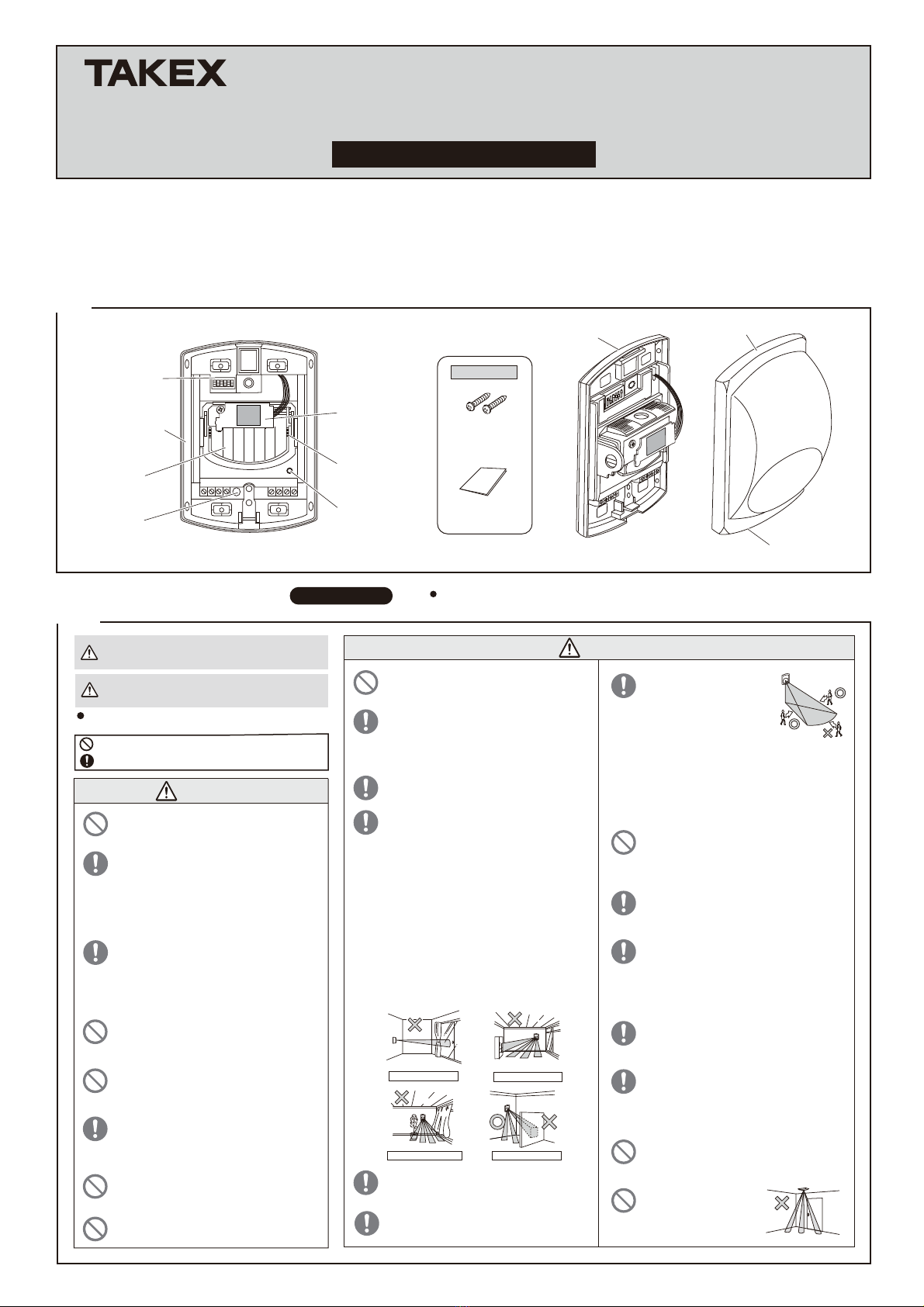
MODE SELECTOR Accessories
Instruction manual
: 1 pc
Self-tapping screw
(ø4 x 30)
: 2 pcs
HORIZONTAL
ADJUSTMENT
WIRING CHANNEL
BASE
1PARTS DESCRIPTION
Instruction Manual
PASSIVE INFRARED SENSOR
PA-4810E ・PA-4820E
(WIDE ANGLE) (LONG RANGE)
ALARM LED /
MEMORY LED
(Red)
COVER
MIRROR UNIT
HEAD UNIT
COVER LOCKING SCREW
TAMPER SWITCH
We appreciate your purchase of a TAKEX passive infrared sensor. This sensor will provide long and dependable service when properly installed.
Please read this Instruction Manual carefully for correct and effective use.
Please Note : This sensor is designed to detect intrusion and to initiate an alarm ; it is not a burglary-preventing device.
TAKEX is not responsible for damage, injury or losses caused by accident, theft, Acts of God (including inductive surge by lightning),
abuse, misuse, abnormal usage, faulty installation or improper maintenance.
Caution
Plants/Curtain
Refrigerator
Shielding objects
Warning
2PRECAUTIONS Be sure to observe
We categorize these precautions throughout the manual using
the following symbols.
Warning
Caution
An action you must do, and information you should keep in mind
A prohibited action, you must not do.
Facing the window
This manual describes precautions by classifying them based on degrees of danger and
damage that would be generated if using the unit incorrectly.
This indicates the possibility of severe injury, and
even death, if ignored or a user handles the unit
incorrectly.
This indicates the possibility of minor injury and/or
damage to properties, or of a notification delay in your
system due to false operations and/or non-detection, if
ignored or a user handles the unit incorrectly.
Mount the unit on a solid ceiling or wall surfaces
where reinforcement materials are used. If you
mount the unit on non-wood materials of plaster
board or concrete, securely mount it using
anchors and mounting screws that match the wall
materials. Unstable mounting may result in injury
and/or property damage if the unit falls.
Do not disassemble or modify this device. This
may cause a fire, electrical shock, or malfunction
of the device.
If the following events occur, turn off the power of
the unit immediately, and ask the place of
purchase for repair. Failure to follow this may
result in fire, electric shock, and/or malfunction.
• Smoke, abnormal odor, and/or sound are found
• Liquid, such as water, and/or foreign material
has entered the unit
• The unit has deformed and/or damaged parts
Do not apply impact to the unit.
Strong impact may result in performance
deterioration and/or damage to the unit.
Make sure to perform a sufficient operation
check on the whole system before operation.
Make sure to check operation when you move
tables and partitions and change the layout in
protected rooms.
Refer to the protection area figures, and select
the installation location. Then, check the actual
operation, and adjust the appropriate area.
The unit may not operate properly near devices
that generate a strong electric or magnetic field.
Also, devices near the unit may not operate
properly due to the magnetic field and/or
magnetism generated from the unit.
Make sure to confirm before operation.
Avoid installing the unit in the following places.
Otherwise, non-detection and/or false detection
may occur.
• Places subject to strong direct or reflected light
(sunlight,spotlight)
• Places subject to rapid temperature fluctuations
(air outlets of air-conditioning equipment, etc.)
• Places where moving objects are included in
the protection area (plants, laundry, etc.)
• Places subject to strong vibration and/or
electric noise
• Places where pets, such as dogs and cats,
and/or automatic cleaning robots may pass
• Places where shielding objects (including glass
and transparent resin, etc.) are included in the
protection area (shading parts will not be
detected)
• Places that people can easily touch.
Passive infrared sensors are
designed to catch changes of
far-infrared ray energy.
Energy changes largely when
the human body moves
across the protection area,
which is easy to detect.
However, energy does not change greatly
when the human body comes closer in a
straight line, or stops, which may be difficult to
detect. In addition, if the protection area
environment generates similar changes due to
certain factors, the unit will set off an alarm
without being able to judge properly.
Do not install the unit in places subject to oil
smoke or steam, high humidity, and/or a lot of
dust.Electricity that travels through these
substances may result in fire, electric shock,
and/or false operation.
Securely conduct installation work according to
the instruction manual.
Also, make sure to use the supplied
accessories and specified components.
Failure to follow this may result in injury and/or
property damage in the event of fire, electric
shock or fall of the unit.
This unit is not a waterproof (moisture
proof/rainproof) or dust-proof structure. Do not
use the unit in places subject to water and/or
high humidity, such as bathrooms, and/or
subject to large amounts of dust or sand.
Failure to follow this could result in malfunction.
Ask qualified personnel for any electrical work
necessary for installation, if required.
Failure to follow this may result in fire and/or
electric shock.
Do not touch terminals with wet hands. Failure to
follow this may result in electric shock.
Do not connect devices that exceed the indicated
capacity to the output contact of the unit. Failure
to follow this may result in electric shock, fire,
and/or malfunction.
Use the sensor lock to fix the sensor unit for
operation.
This can prevent injuries, and/or damage to the
unit if the unit falls, as well as prevent the sensor
from being tampered.
Do not use the unit with power voltage levels
other than those specified. Failure to follow this
may result in fire, electric shock, and/or
malfunction.
Do not install this device in a location that cannot
support its weight. This may cause the device to
fall and cause an injury or malfunction of the
device.
This unit is for indoor use. Do not use the unit in
places subject to water and/or high humidity.
Failure to follow this may result in malfunction if
water gets into the unit.
Do not perform aerial wiring of power and signal
cables.
Failure to follow this may result in electric shock,
fire, and/or malfunction.
Do not install the sensor
directly on the ceiling
(When installed on ceilling,
use optional attachment
BCW-401)
COVERAGE
3INSTALLATION
4
(1)
84°
68°
38°
21°
10°
22°
MIN. COVERAGE MIN. COVERAGE
64°
44°
29°
19°
11°
4°
22°
40' (12m)
5.25' (16m)
9.8' (3m)
WIDE ANGLE
〈PA-4810E〉〈PA-4820E〉
LONG RANGE
40' (12m)
82' (25m)
82' (25m)
9.8' (3m)
9.8' (3m)9.8' (3m)
(4)
(2)
→
Connect wires.
(3) Attach the cover, and
check operation.
Install the base on the wall.
Knockout appropriate
wiring and mounting screw
holes. Feed wire through
knockout.
*Two mounting pitches are
available for mounting to a
single gang box.
*When installed on wall
corner, make use of 4
mounting knockouts on
sides.
*Break the knockout and
pull in the wire through it.
When using the upper
wiring knockouts, route
wires along wiring
channel on either side
( portion) of plastic
frame of P.C. Board.
Detach the cover.
Loosen screw until
cover slips.
CAUTION : Do not
remove screw from
cover.
This will prevent locking
nut from falling out and
becoming lost.
【TERMINAL ARRANGEMENT】
12
3 4
6
87
POWER (non-polarity)
9.5V to 28V DC
TAMPER OUTPUT
Dry contact
ALARM OUTPUT
Dry contact
(semi-conductor)
N.C./N.O. selectable
Reset : approx. 2 sec.
30V DC (24V AC) 0.25A Max.
(Protective resistor 3.3Ω)
N.C. contact
Operation : Open when cover is detached.
30V DC 0.1A Max.
25mA Max.
LED ControlL/C
5
VACANT
{
{
{
{
【BASIC CONNECTION】【ALLOWABLE WIRING DISTANCE BETWEEN
SENSOR AND POWER SOURCE】
Distance at 12VDC Distance at 24VDC
Size of wire used
3800ft (1160m) 22000ft ( 6700m)
5900ft (1800m) 34000ft (10400m)
AWG 22 (Dia.0.65mm)
AWG 18 (Dia.1.0mm)
AWG 16 (Dia.1.25mm) 9300ft (2840m) 55000ft (16500m)
HORIZONTAL
ADJUSTMENT
VERTICAL
ADJUSTMENT
Protrusion
Protrusion
AREA SETTING
■ADJUST UNDER AIMING POSITION■ADJUSTMENT OF THE FIELD VIEW
6
WIRING
5
Sensor (N.C.)Sensor (N.C.)
POWER
Signal Input
Adjust/check detection area visually in the following procedure when operation check shows improper area adjustment.
●
visible
invisible
TAMPER
VACANT L/CPOWER ALARM
[When two units are used]
Note : 1)
2)
*Allow approx. one minute for warm-up after power is applied.
(Alarm LED is flashing) In the meantime, no alarm is initiated.
*After the one minute has passed the unit will be in the armed
condition and will trigger when detecting a human body.
When operation check shows improper area setting, check visually its area setting.
(1) Slide the head unit to bring the sensor
unit into aiming position. Slip to the
arrow direction and it will be
automatically locked at testing position.
(2) Adjust the coverage by moving the
mirror so that LED on the head unit is
visible through mirror from location to
be protected.
(3) After adjustment is completed,
lightly push head unit. It will
replace to the armed position
automatically.
*When head unit is placed at
testing position, alarm LED
lights and alarm output
continuously outputs (Trouble
alarm).
You see a
mirror light
red.
parabolic mirror
(inside the sensor)
Adjust with
parabolic mirror
rotating by hands.
Do not touch the
mirror surface.
●Hold parabolic
mirror by hands
and push for
horizontal
adjustment.
12 34 56 78
Maximum wiring distance, when two or more sets are
connected, is the value above divided by numbers of
sets.
The signal line can be wired to a distance of 3,280 ft
(1,000m) with AWG 22 (0.65mm dia.) wire.
NOTE :
NOTE :
NOTE :
2 : Low voltage
3 : Failure to replace
TROUBLE ALARM
NOTE :
1 : Unit trouble
ON
OFF
ON
OFF
120%100%
(Factory set)80%60%
Switch 4・5
123456
FACTORY SET
ALARM CONTACT CHENGEOVER
SETTING OF SENSITIVITY
FINE MOTION DETECTION
Switch 3
ON
N.O.
OFF
N.C.
(Factory set)
Switch 6
ON
Fine motion
OFF
Intruder detection
(Factory set)
■LED CONTROL
LED CONTROL FUNCTIONS
Wire terminal 6 (L/C) through an external control contact
switch with Power (-).
●OPERATION
Turn the Mode selector 1 OFF.
When the switch is turned ON, the alarm LED lights at alarm.
When the switch is turned OFF, the alarm LED does not light.
POWER
Signal Input
Contact switch
Sensor operation can be adjusted to fit the environmentals / applications with the built-in mode selector.
ALARM LED
ALARM MEMORY
Switch 2
ON
OFF
(Factory set)
Switch 1
ON
OFF
(Factory set)
6 6
SENSOR FUNCTIONS
7
The alarm LED will light up, synchronized with the alarm
contact, if you set the mode
selector at ON.
Change alarm contact to N.O. when sensor is used for
an application except security purpose, such as light
control.
Make use of the ne motion detection (motion of
hands or body) at narrow range.
When operation check shows you high sensitivity of
sensor, change setting of sensitivity with mode
selector and re-check operation.
Four settings are available.
This mode is so
sensible to detect
even a slight
motion that the
performance to
discriminate
small animals
might be low.
NOTE : Same LED is used to indicate both alarm and
alarm memory.
Memory LED will inform you which sensor initiated an
alarm during alert conditions when two or more sensors are
connected on the same line.
When this setting is "ON".
Memory is always stored
when sensor is armed.
When an alarm has been
activated, the memory LED
ashes for 3 min. and then
remains lit for 47 min.
It automatically reset and
memory is also canceled.
This function checks / monitors sensor unit itself in
accordance with built-in program.
When trouble is found out as a result of the check /
monitor, alarm LED lights and an alarm signal also
continuously outputs.
Trouble alarm outputs when inner circuit / wiring is
damaged / broken.
See 9, troubleshooting and remedy table.
The monitor functions regardless of mode
settings but an alarm is not indicated in case
of setting alarm LED at OFF position.
When power is reset during the alarm
status, trouble alarm stops only for
warming up time.
When power voltage of sensor drops down (approx.
8.5V DC or less), trouble alarm outputs before sensor
operation comes to be unstable due to low voltage.
See troubleshooting and remedy table.
Trouble alarm outputs to prevent failing to replace
sensor head unit which is set for aiming. Alarm
stops when the sensor head unit is replaced to alert
position.
The monitor functions regardless of mode
settings but an alarm is not indicated in case
of setting alarm LED at OFF position.
When power voltage recovers to normal level
during the alarm status, trouble alarm stops.
The monitor functions regardless of mode
settings, but an alarm is not indicated when
alarm LED is set to OFF position.
MAINTENANCE
Sometimes inactive.
Analyze possible problems according to the following table. If normal operations cannot be restored by this means, contact either the dealer from whom you bought the unit or TAKEX.
Trouble Possible cause Corrective action
●
●
●
●
●
●
●
●
●
●
●
●
●
●
●
●
●
●
●
●
●
●
●
●
●
●
●
●
●
●
●
●
●
●
●
●
●
●
●
●
Either power is OFF (including broken cable) or power voltage is too low.
Not yet 1 min. after power turned on. (Is alarm LED flickering ?)
There is an obstacle in front of the detection area.
Check the power cable and adjust power voltage properly.
Allow for warm-up time.
Remove the object.
Improper detection area adjustment.
Improper detection area adjustment .
Readjust the detection area setting.
Cover surface soiled. Clean cover with a soft cloth. (Do not use thinner, etc.)
Activated when no person has
passed.
Improper power supply. Correct power supply.
Something moving in protected area or too rapid temperature variations.
Trouble alarm initiated again after warming-up period, though power is reset.
A source of electrical noise (broadcasting station, amateur radio etc.) nearby.
Strong sunlight reflection or direct light hitting the unit.
The detector reacts to passersby outside.
Remove the cause.
Change the installation location.
Shield sunrays with a blind.
Readjust the detection area.
Alarm LED lights, though
connected units are inactive.
Poor contact output connection or broken wire. Check the wiring.
Connected units are damaged. Check connected units.
Damaged alarm contact. Check alarm output terminals with tester.
Alarm LED continues to light
and alarm continues to be
initiated. (Trouble alarm)
Head unit fails to be replaced. Replace to armed position.
Too low power voltage. Adjust power voltage properly.
There is a possibility of inner broken wire/damage.
To clean the device, use a soft, wet cloth and then wipe off any water drops.
If the device is particularly dirty, dip the soft cloth in the water that contains a weak neutral detergent.
Wipe the device gently with the cloth, then wipe off any detergent that remains. Do not use substances such as thinner or benzene.
(The plastic parts may deform, discolor or change their properties.)
Perform operation checks on a regular basis.
When installation is completed, turn the power "ON" and check operation, after about 1min. warming up time, as follows:
1. Make sure that alarm LED nishes ickering.
2. Walk test in the protected area to check if an alarm is initiated.
Check alarm LED and control panel for sensor operation.
3. After correct operation has been conrmed, use the mode selector switch to disable the
alarm LED, if required.
Reposition so that the range is less than 40ft. (12m) (Wide angle) or
82ft. (25m) (Long range)
The detection range exceeds. 40ft. (12m) (Wide angle)
82ft. (25m) (Long range)
OPERATION CHECK
8
9TROUBLESHOOTING
Completely inactive.
Built-in CPU automatically checks/monitors
sensor unit function, regardless of mode settings
except a part of features.
Unit trouble : Monitoring inner circuit and wiring damage
Operation : Trouble alarm
Low voltage trouble : Monitoring low voltage
Operation : Trouble alarm
Positioning trouble : Monitoring failure to replace view finder
Operation : Trouble alarm
Limited Warranty :
TAKEX products are warranted to be free from defects in material and workmanship for 12 months from original date of shipment. Our warranty does not cover damage
or failure caused by natural disasters, abuse, misuse, abnormal usage, faulty installation, improper maintenance or any repairs other than those provided by TAKEX. All
implied warranties with respect to TAKEX, including implied warranties for merchantability and implied warranties for fitness, are limited in duration to 12 months from
original date of shipment. During the Warranty Period, TAKEX will repair or replace, at its sole option, free of charge, any defective parts returned prepaid. Please provide
the model number of the products, original date of shipment and nature of difficulty being experienced. There will be charges rendered for product repairs made after our
Warranty Period has expired.
In Japan
Takex America Inc.
4/15 Howleys Road, Notting Hill,
VIC, 3168
Tel : +61 (03) 9544-2477
Fax : +61 (03) 9543-2342
Takenaka Engineering Co., Ltd.
83-1, Gojo-sotokan,
Higashino, Yamashina-ku,
Kyoto 607-8156, Japan
Tel : 81-75-501-6651
Fax : 81-75-593-3816
http : // www. takex-eng. co. jp /
Takex America Inc.
151 San Zeno Way
Sunnyvale,
CA 94086, U.S.A
Tel : 408-747-0100
Fax : 408-734-1100
http : // www. takex. com
Takex Europe Ltd.
Aviary Court, Wade Road,
Basingstoke, Hampshire. RG24 8PE, U.K.
Tel : (+44)01256-475555
Fax : (+44)01256-466268
http : // www. takex. com
In the U.S. In the U.K.
In Australia
Passive infrared sensor
PA-4810E PA-4820E
Passive infrared (QUAD)
72 (18 pairs) 24 (6 pairs)
9.5 to 28V DC (non-polarity)
3min. -Flickering, 47min. -Lighting
Sensitive zone : 36 pairs Sensitive zone : 12 pairs
Indoor (wall / pillar)
Terminals
5.82oz (165g)
resin (White)
Model
Detection system
Coverage
Sensitive zone
Supply voltage
Current consumption
Alarm output
Tamper output
Alarm memory
Fine motion detection
LED (Red)
Trouble signal
Ambient temperature
range
Mounting position
Wiring connections
Weight
Appearance
Adjustment range
10 SPECIFICATIONS
The specifications are subject to change without notice.
25mA Max. (N.C./N.O. contact)
Dry contact (Semi-Conductor)
Reset : Approx. 2 sec. (N.C./N.O. selectable)
30V DC (24V AC) 0.25A Max. (protective resistor 3.3Ω)
Dry contact (type N.C.)
Open when cover is detached
30V DC 0.1A Max.
Alarm LED Flickering (every 0.5 sec.) : Warming-up
Lighting (approx.2sec.) : Alarm
Flickering (every 0.25 sec.) : Trouble indication
Continuous lighting : Trouble alarm
(Disabled is LED except trouble indicaiton)
Memory LED Flickering : Memory activated
Lighting : Memory indicated
+14°F to +122°F (without dewdrops)
(−10°C to +50°C)
Vertically 20° Horizontally ±5°
Wide angle protection
40' (12m) Max.
Long range protection
82' (25m) Max.
Mounting hole
11 EXTERNAL DIMENSIONS
3.54" (90mm)
5" (127mm)
2.36" (60mm)
P.C.D. 3.29" (83.5mm)
P.C.D. 3" (76mm)
CORNER MOUNTING HOLE
4 CORNERS (KNOCKOUT)
WALL MOUNTING
HOLE
(KNOCKOUT)
WIRING HOLE
(KNOCKOUT)
WIRING HOLE
(KNOCKOUT)
2021.8.26

This manual suits for next models

1

Other Takex Accessories manuals

Takex PS-520E User manual

Takex

Takex PS-520E User manual

Takex PXB-100ATC User manual

Takex

Takex PXB-100ATC User manual

Takex F71 Series User manual

Takex

Takex F71 Series User manual

Takex PA-6612E User manual

Takex

Takex PA-6612E User manual

Takex MS-100E User manual

Takex

Takex MS-100E User manual

Takex TXF-125E-KH User manual

Takex

Takex TXF-125E-KH User manual

Takex MW-50L User manual

Takex

Takex MW-50L User manual

Takex PR-5B User manual

Takex

Takex PR-5B User manual

Takex TXF-125 Series User manual

Takex

Takex TXF-125 Series User manual

Takex MS-12TE User manual

Takex

Takex MS-12TE User manual

Takex PR-11BE User manual

Takex

Takex PR-11BE User manual

Takex FS-3500E User manual

Takex

Takex FS-3500E User manual

Takex PA-480S User manual

Takex

Takex PA-480S User manual

Takex F85R User manual

Takex

Takex F85R User manual

Takex PIR-T40NAM(W) User manual

Takex

Takex PIR-T40NAM(W) User manual

Takex ASW-SG85F User manual

Takex

Takex ASW-SG85F User manual

Takex PB-30TK User manual

Takex

Takex PB-30TK User manual

Takex MW-100AL Manual

Takex

Takex MW-100AL Manual

Takex MS-12TE User manual

Takex

Takex MS-12TE User manual

Takex TX-114TR User manual

Takex

Takex TX-114TR User manual

Takex PXB-50HF-KH User manual

Takex

Takex PXB-50HF-KH User manual

Takex PIR-T40NAM User manual

Takex

Takex PIR-T40NAM User manual

Takex FS-1000E User manual

Takex

Takex FS-1000E User manual

Takex PA-15WE User manual

Takex

Takex PA-15WE User manual

Popular Accessories manuals by other brands

Panasonic FX-301-F instruction manual

Panasonic

Panasonic FX-301-F instruction manual

Jula Hard Head 007588 operating instructions

Jula

Jula Hard Head 007588 operating instructions

iB COLUMBO user manual

iB

iB COLUMBO user manual

ROBOTIQ FT 300-S manual

ROBOTIQ

ROBOTIQ FT 300-S manual

IOGear GMP1001B quick guide

IOGear

IOGear GMP1001B quick guide

Telco Sensors SpaceMaster Series user manual

Telco Sensors

Telco Sensors SpaceMaster Series user manual

PCB 4115A-02A Installation and operating manual

PCB

PCB 4115A-02A Installation and operating manual

Motorfist Argo Avalanche user manual

Motorfist

Motorfist Argo Avalanche user manual

PCB Piezotronics 034AD100JW Installation and operating manual

PCB Piezotronics

PCB Piezotronics 034AD100JW Installation and operating manual

Vicinoate 158746.01 user manual

Vicinoate

Vicinoate 158746.01 user manual

HomeSeer HS-DS100+ user manual

HomeSeer

HomeSeer HS-DS100+ user manual

LEGRAND Wattstopper CI-355 installation instructions

LEGRAND

LEGRAND Wattstopper CI-355 installation instructions

Powerfix Profi PMT 1.1 A1 translation of original operation manual

Powerfix Profi

Powerfix Profi PMT 1.1 A1 translation of original operation manual

EDS i1 Series user manual

EDS

EDS i1 Series user manual

S+S Regeltechnik HYGRASGARD AFF Series Operating Instructions, Mounting & Installation

S+S Regeltechnik

S+S Regeltechnik HYGRASGARD AFF Series Operating Instructions, Mounting & Installation

Silverline Mice & Rat Free 50 manual

Silverline

Silverline Mice & Rat Free 50 manual

PRIMAVERA Ambiente Important information

PRIMAVERA

PRIMAVERA Ambiente Important information

WPI ISO-COP-2 instruction manual

WPI

WPI ISO-COP-2 instruction manual

manuals.online logo
manuals.online logoBrands
  • About & Mission
  • Contact us
  • Privacy Policy
  • Terms and Conditions

Copyright 2025 Manuals.Online. All Rights Reserved.