Takex PIR-T40NAM(W) User manual

①
3,571$0:LVSDVVLYHLQIUDUHGVHQVRUWKDWGHWHFWVIDULQIUDUHGUD\VHPLWWHGIURPWKHKXPDQERG\DQGRXWSXWVDFRQWDFWVLJQDO
6LQFHWKLVXQLWVLJQLILFDQWO\UHGXFHVORVWDQGIDOVHGHWHFWLRQXVLQJWKHXQLTXHWULSOHPLUURUDQGVLJQDOSURFHVVLQJV\VWHPVLWFDQEH
XVHGERWKIRULQGRRUDQGRXWGRRUDSSOLFDWLRQV7KLVXQLWKDVWKHIROORZLQJIHDWXUHVVXLWDEOHIRUPXOWLSOHDSSOLFDWLRQV
'HWHFWLRQGLVWDQFHXSWRP·(0D[PZLWKKLJKGHQVLW\PRGH)
'HWHFWLRQGLVWDQFHDQGGLUHFWLRQDGMXVWDEOH
0RXQWLQJKHLJKWRIWRP·WR·IRUQRUPDORSHUDWLRQPD[P·LQVSHFLDOL]HGRSHUDWLRQPRGHV
(TXLSSHGZLWK1&FRQWDFWRXWSXWIRUVHFXULW\DQG12FRQWDFWRXWSXWIRUDFWLYDWLRQRIDQFLOODU\GHYLFHV
&DQEHPRXQWHGRQZDOOVXUIDFHVDVZHOODVRQSROHVFHLOLQJVDQGXQGHUHDYHVXVLQJWKHRSWLRQDODFFHVVRULHVVROGVHSDUDWHO\
(TXLSSHGZLWKDQWLPDVNLQJDQGEDFNWDPSHUIXQFWLRQVIRUPRUHVHFXUHSURWHFWLRQ
>&RYHUXQLW@
0HPRU\/('
5HGHPEHGGHG
$ODUP/('
5HGHPEHGGHG &RYHUORFNLQJVFUHZ
:LULQJKROHIRU
H[SRVHGZLULQJ
.QRFNRXW
:LULQJKROH
ZLWKJURPPHW
%DFNWDPSHU
>6HQVRUXQLW@
0RGHVHWWLQJ
WDEOH $UHDVHWWLQJ
WDEOH
0RGHVHOHFWRU
,QGLFDWRU
$UHDVHOHFWRU
$OLJQPHQW
OHYHU
>0LUURUXQLW@
7HUPLQDOEORFN
:LULQJKROH
ZLWKJURPPHW
0LUURU
ORFNLQJVFUHZ
$FFHVVRULHV
7DSSLQJVFUHZ
Ѯð
SFV
,QVWUXFWLRQ
PDQXDO
7KLVGRFXPHQW
$UHDPDVNLQJVKHHW
VKHHW
$QWLELUGVSLNH
SFV
Thank you for purchasing this product.
Before using the product, please read this instruction manual to ensure correct operation.
TRIPLE MIRROR PASSIVE SENSOR
Instruction Manual
PIR-T40NAM (W)
352'8&7'(6&5,37,21
3$576'(6&5,37,21
:LULQJKROHIRU
H[SRVHGZLULQJ
.QRFNRXW
(Vertical curtain protection)

②
3HWVVXFKDVGRJVFDWVDQGELUGV
6KLHOGLQJREMHFWV 3ODFHVWKDWSHRSOHFDQHDVLO\WRXFK
6WURQJOLJKWWKDWKLWVWKHVHQVRU
6WURQJYLEUDWLRQDQGRUHOHFWULFQRLVH
Warning
Caution
Do not use the unit with power voltage levels other than
those specified. Failure to follow this may result in fire,
electric shock, and/or malfunction.
Do not connect devices that exceed the indicated capacity to
the output contact of the unit. Failure to follow this may
result in electric shock, fire, and/or malfunction.
Do not touch terminals with wet hands. Failure to follow
this may result in electric shock.
If the following errors/malfunctions occur, power off the
unit immediately, and contact your dealer.
Failure to follow this may result in fire, electric shock,
and/or malfunction.
s3MOKEABNORMALODORANDORSOUNDAREFOUND
s,IQUIDSUCHASWATERANDORFOREIGNMATERIALHAS
entered the unit
s4HEUNITISDEFORMEDANDORPARTSAREDAMAGED
$ONOTDISASSEMBLEORMODIFYTHEUNIT
Failure to follow this may result in fire, electric shock,
and/or malfunction.
Mount the unit on a solid ceiling or wall surfaces where
reinforcement materials are used. If you mount the unit on
NONWOODPLASTERBOARDORCONCRETESECURELYMOUNTITUSING
anchors and mounting screws that match the wall
materials. Failure to follow this may result in injury and/or
property damage if the unit falls.
Do not install the unit in a place and/or with a mounting
method that cannot support its weight.
Failure to follow this may result in injury and/or property
damage when the unit falls.
Do not apply impact to the unit.
Applying strong impact to the unit may result in
performance deterioration and/or damage to the unit.
4HEUNITMAYNOTOPERATEPROPERLYNEARDEVICESTHAT
generate a strong electric or magnetic field. Also, devices
near the unit may not operate properly due to the
magnetic field and/or magnetism generated from the unit.
-AKESURETOCHECKITBEFOREOPERATION
Make sure to perform sufficient operation checks on the
WHOLESYSTEMBEFOREOPERATION
3ECURELYCONDUCTINSTALLATIONWORKACCORDINGTOTHE
instruction manual. Also, make sure to use the supplied
accessories and specified components. Failure to follow this
may result in injury and/or property damage in the event
of fire or electric shock, if the unit falls.
#ONTACTQUALIFIEDPERSONNELFORANYELECTRICALWORK
NECESSARYFORINSTALLATIONIFREQUIRED
Failure to follow this may result in fire and/or electric
shock.
$ONOTINSTALLTHEUNITINPLACESSUBJECTTOOILSMOKESTEAM
high humidity, and/or a lot of dust. Electricity transmitted
through oil, water, and/or dust may result in fire, electric
shock, and/or false operation.
$ONOTPERFORMAERIALWIRINGOFPOWERANDSIGNALCABLES
Failure to follow this may result in electric shock, fire,
and/or malfunction.
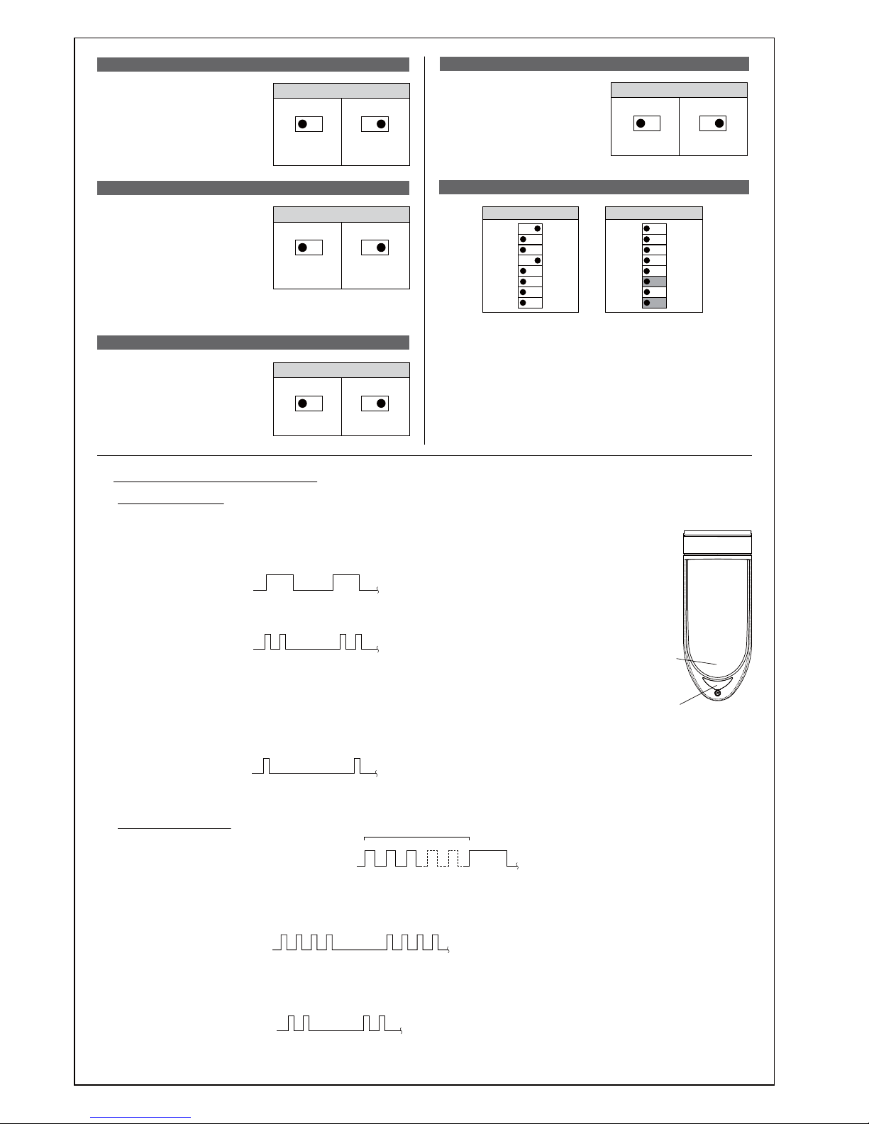
Passive infrared sensors are designed to detect changes of
far-infrared ray energy. Energy changes largely when the
HUMANBODYMOVESACROSSTHEDETECTIONAREA(OWEVER
ENERGYDOESNOTCHANGEGREATLYWHENTHEHUMANBODY
comes closer in a straight line, or stops.
In addition, if the
detection area
environment generates
similar changes due to
certain factors, the unit
will issue an alarm
WITHOUTBEINGABLETO
judge properly.
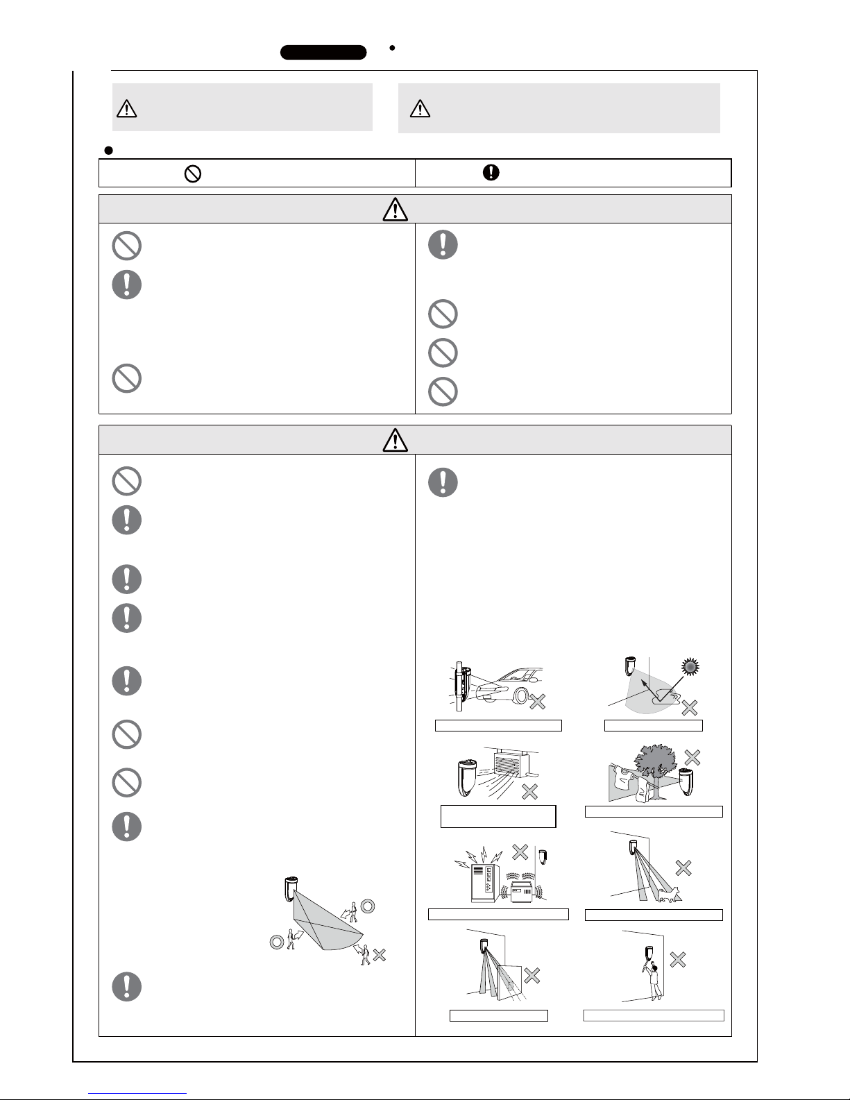
Avoid installing the unit in the following places. Otherwise,
false detection may occur.
s0LACESSUBJECTTOSTRONGDIRECTORREFLECTEDLIGHTSUNLIGHT
spotlight)
s0LACESSUBJECTTORAPIDTEMPERATUREFLUCTUATIONSAIR
OUTLETSOFAIRCONDITIONINGEQUIPMENTETC
s0LACESWHEREMOVINGOBJECTSAREINCLUDEDINTHEDETECTION
AREATREESBRANCHESANDLEAVESLAUNDRYETC
s0LACESSUBJECTTOSTRONGVIBRATIONANDORELECTRICNOISE
s0LACESWHEREDOGSCATSBIRDSANDORAUTOMATICCLEANING
ROBOTSMAYPASS
s0LACESWHERESHIELDINGOBJECTSINCLUDINGGLASSAND
transparent resin, etc.) are included in the detection area
SHADINGPARTSWILLNOTBEDETECTED
s0LACESWHERETHESENSORPARTLOOKSINCLINEDFROMTHEFRONT
VIEWTHEAREACANNOTBEPROPERLYCONFIGURED
s0LACESTHATINTRUDERSCANEASILYTOUCH
3ETTHEAREAWITHINTHERATEDDETECTIONDISTANCERANGE
according to the instruction manual. If you use the unit
outside the specified range, an appropriate area will not
HAVEBEENCONFIGUREDANDTHEUNITMAYOPERATEUNSTEADILY
and/or detection may fail.
$LURXWOHWVRIDLUFRQGLWLRQLQJ
HTXLSPHQW
6XQOLJKWUHIOHFWLRQ
7UHHVEUDQFKHVDQGOHDYHVODXQGU\
Warning Caution
$SURKLELWHGDFWLRQ\RXPXVWQRWGR
$QDFWLRQ\RXPXVWGRDQGLQIRUPDWLRQ\RX
VKRXOGNHHSLQPLQG
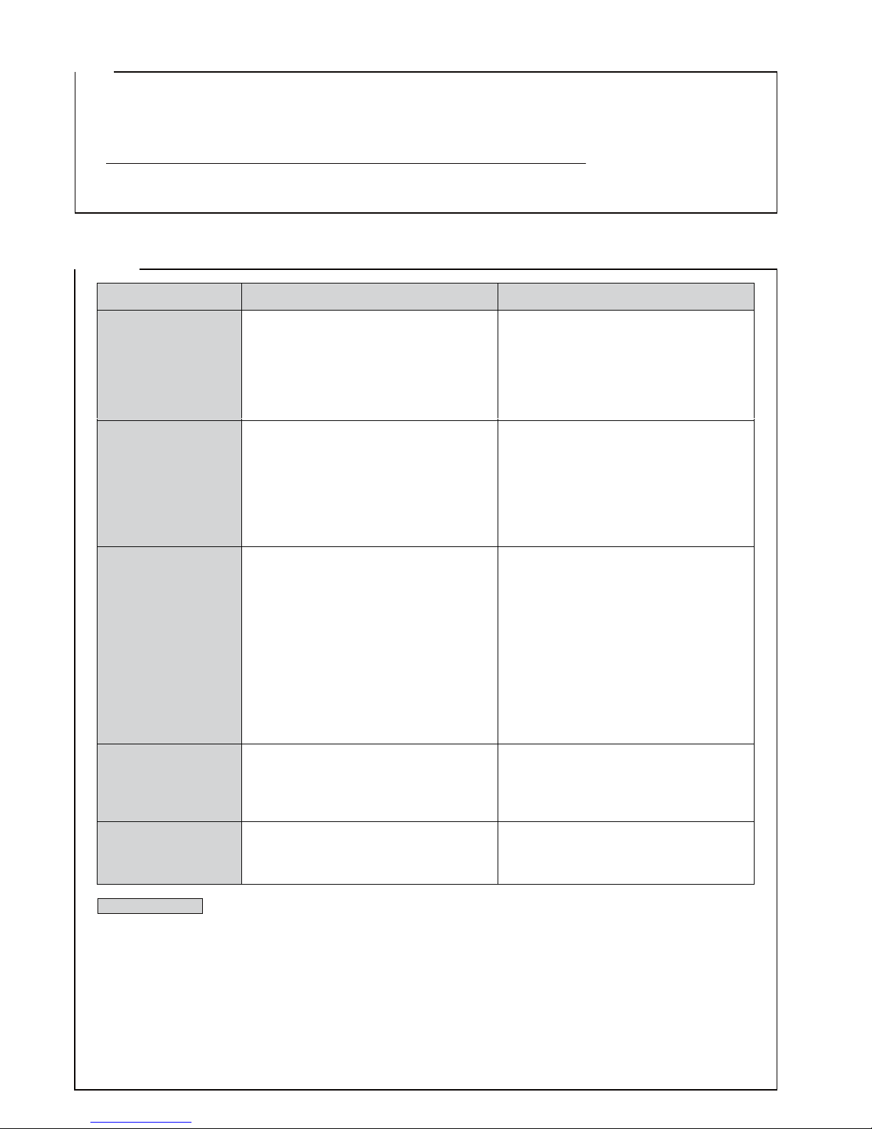
35(&$87,216 7KLVPDQXDOGHVFULEHVSUHFDXWLRQVE\FODVVLI\LQJWKHPEDVHGRQGHJUHHVRIGDQJHUDQG
GDPDJHWKDWZRXOGEHJHQHUDWHGLIXVLQJWKHXQLWLQFRUUHFWO\
Be sure to observe
7KLVLQGLFDWHVWKHSRVVLELOLW\RIVHYHUH
LQMXU\DQG HYHQ GHDWK LI LJQRUHG RU D
XVHUKDQGOHVWKHXQLWLQFRUUHFWO\
7KLV LQGLFDWHV WKH SRVVLELOLW\ RI PLQRU LQMXU\ DQGRU
GDPDJH WR SURSHUWLHV RU RI D QRWLILFDWLRQ GHOD\ LQ
\RXU V\VWHP GXH WR IDOVH RSHUDWLRQV DQGRU
QRQGHWHFWLRQLILJQRUHGRUDXVHUKDQGOHVWKHXQLW
LQFRUUHFWO\
We categorize these precautions throughout the manual using the following symbols.

③
Caution
Refer to the detection area chart, and select the installation
location. Then, check the actual operation, and adjust the
appropriate area.
Perform the operation check after installation and also on
periodic basis to make sure that there is no problem in the
operation.
Install the unit in the
location where the
detection area faces toward
a place that intruders may
pass through.
After installation, make
sure to adjust the detection
area and perform sufficient
operation check.
This unit is for wall mounting. When installing it on poles,
ceilings, or under eaves, use the specified attachments (sold
separately).
This unit has a rainproof structure, not a waterproof
structure. Do not hose it directly. Do not use the unit in
places subject to water and/or constant high humidity, such
as bathroom. Failure to follow this could result in
malfunction.
Avoid operation in places where there is not enough space
for the detection area to pass through without being
obstructed. It may cause false or lost detection.
When this operation is obliged, selecting "high density
mode" is recommended.
Note, however, that the performance to prevent
malfunction against environmental change and small
animals will be reduced with this mode.
In order to maintain the rainproof structure of this unit,
mount it in the correct direction. Mounting it sideways or
upside down may result in malfunction.
Apply caulking to wiring holes based on the mounting wall
material, if necessary, in order to maintain rainproof
performance.
Mount the unit straight so that it does not look inclined
from the front and side view.
When mounting on the wall, adjust the detection area so
that it does not cover the wall surface. It may cause false
or lost detection.
Move the detection area horizontally by one step or more
to keep it away from the wall.
Adjust the detection area
so that it does not go
beyond the site.
(Unexpected objects may
be detected)
'(7(&7,21$5($
Please pay attention that the detection distance changes by
below factors
* Mounting height
(The higher installation position, the longer detection
distance becomes)
* Inclination in the grand in detection area
The configuration of detection area based on the level ground.
In case of inclined ground, the detection distance becomes
long in the downslope, the detection distance becomes short
in the upslope.
And it is impossible to configure the proper detection area in
where there are in inclined or stepped ground in detection area.
There is a possibility that the false or lost detection occur under
this situation.
Please check the proper position in each detection zone using
LED aiming function and do the operation check by walking test.
Mountingheight:2.0m
Detectiondistance:40m
Mountingheight:2.0m
Detectiondistance:20m
※Adjustthemountingheightofthe
sensorusingthecenterofthe
sensorhousingasaguide.
※7KHULJKWDQGOHIWDX[LOLDU\]RQHLQ
QHDUGHWHFWLRQDUHDEHFRPHV
HIIHFWLYHZKHQWKHDUHDPDVNLQJ
SODWHLVUHPRYHG
1°
80°
3.2m(10.5)
1.1m(3.5)
1.1m(3.5)
0.9m(3)
0.3m(1)
1.4m(4.5)
2m
(6.6)
5m
(16)
10m
(33)
15m
(49)
20m
(66)
25m
(83)
30m
(100)
35m
(115)
40m
(135)
0
Auxiliaryzone
CENTERZONE
【Topview】
【Topview】
【Sideview】
【Sideview】
83°
3°
1.0m(3.5)
0.5m(1.5)
1.6m(5.5)
0.6m(2)
0.6m(2)
0.6m(2)
2m
(6.6)
5m
(16)
10m
(33)
15m
(49)
20m
(66)
0
CENTERZONE
Auxiliaryzone
:DOO
VXUIDFH
:DOO
VXUIDFH
:DOO
VXUIDFH
6HQVRU
6HQVRU
6HQVRU
'HWHFWLRQ
DUHD
'HWHFWLRQDUHD
'HWHFWLRQDUHD
In case of the detection along the wall, adjust the detection
area by noting the following points.
:DOOIHQFHHWF

④
■
Precautions on the detection area setting
5HIHUWR´$'-8670(172)'(7(&7,21$5($µ
$WWDFKWKHDUHDPDVNLQJVKHHWLQRUGHUIURPWKHORQJHVWSDUWRI
WKHGHWHFWLRQDUHDDQGDGMXVWWKHGHWHFWLRQGLVWDQFH
●Detection area distance adjustment
6LQFHWKHGHWHFWLRQ]RQHH[WHQGVXQWLOLWKLWVWKHJURXQGRU
ZDOOVXUIDFHWKHXQLWPD\GHWHFWREMHFWVHYHQLQSODFHV
EH\RQGWKHVSHFLILHGGLVWDQFH,QRUGHUWRDYRLGXQH[SHFWHG
GHWHFWLRQDGMXVWWKHDUHDVXIILFLHQWO\
●Detection area range
:KHQWKHGHWHFWLRQDUHDLVDGMXVWHGWROHVVWKDQPVHWDUHDVHOHFWRUWRP
SRVLWLRQDQGPDVNWKHGHWHFWLRQDUHDXVLQJWKHVXSSOLHGDUHDPDVNLQJVKHHWDQGVHW21LQ
WKHVKRUWGLVWDQFHVHWWLQJGLSVZLWFKLQPRGHVHOHFWRU
5HIHUWR)81&7,21$'-8670(172)'(7(&7,21$5($
:KHQPDVNLQJHDFKGHWHFWLRQDUHDIURP①WR④DWWDFKWKHDUHD
PDVNLQJVKHHWWRWKHVXUIDFHRIWKHPLUURUXQLWFRUUHVSRQGLQJWR
WKHGHWHFWLRQDUHDDVLQGLFDWHGZLWKWKHDUURZ
$YRLGVRLOLQJWKHPLUURUVXUIDFHVZLWKGLUWRUILQJHUSULQW
■Masking method of the detection area
①
③
②
Areamaskingsheet
①
③
②
④
④
【Sideview】
【Topview】
16m
(53)
12m
(40)
8m
(26) 10m
(33)
Installation
height
(3.0m)
①②③④
①②③④
●Detection area setting to less than 20m(66')
Attach the area masking sheet in order (①→④) from
the longest part of the detection area, and adjust the
detection distance.
■Near detection area
:KHQGHWHFWLRQRIQHDUHUDUHDLVUHTXLUHGUHPRYH$UHDPDVNLQJ
SODWHVWRUHGLQVLGHVRWKDWWKHULJKWDQGOHIWDX[LOLDU\GHWHFWLRQ]RQH
FDQIXQFWLRQ
&KHFNWKHGLUHFWLRQRIDX[LOLDU\GHWHFWLRQ]RQHDQGWKHGHWHFWLQJ
SHUIRUPDQFHIRUSURSHURSHUDWLRQ
5HPRYHDOO$UHDPDVNLQJSODWHVWRUHGLQ[UHIOHFWLRQPLUURULQVLGH
WKHVHQVRUXQLW
$YRLGVRLOLQJWKHPLUURUVXUIDFHVZLWKGLUWRUILQJHUSULQW
【Topview】
Auxiliarydetectionzone
Adhesive
C
F
R
Aeamasking
plate
●Detecting near area
●Detecting area directly beneath the sensor
:KHQGHWHFWLQJDUHDGLUHFWO\XQGHUWKHVHQVRUVHOHFW21LQ',3
VZLWFK&UHHS]RQHGHWHFWLRQVHWWLQJLQ0RGHVHOHFWRU
3OHDVHQRWHWKDWWKHSHWLPPXQLW\SHUIRUPDQFHGHFUHDVHVZKHQWKLV
VHWWLQJLVHQDEOHG
7KLVVHWWLQJLVGLVDEOHGLQWKHKLJKGHQVLW\PRGH
5HIHUWR)81&7,21
To disable the auxiliary zone after removing "Area masking
plate (x3)", replace them in the original positions.
In that case, remove the adhesive, and replace "Area masking
plate" in the positions of "F", "R" and "C", as indicated on the
adjacent diagram.
Each of the 3 "Area masking plates" are uniquely shaped so
make sure to replace them correctly before operation.
:KHQWKHGHWHFWLRQDUHDLVDGMXVWHGWROHVVWKDQPSOHDVH
PDVNWKHGHWHFWLRQDUHDXVLQJWKHVXSSOLHGDUHDPDVNLQJVKHHW

⑤
1. Loosen the cover locking screw
and remove the cover unit.
2. Insert the wire through the grommet in the wiring
hole at the bottom of the sensor unit. Break the
mounting hole knockout of the sensor unit and
mount using the supplied tapping screws.
When mounting on the pole
[Use the pole attachment]
When mounting on the ceiling or under eaves
[Use the ceiling attachment]
When mounting the unit on a vertical pole, use the pole attachment
(sold separately). The unit can be mounted on poles of φ38 to φ45mm
(Dia 1.5µto 1.8µ) and φ40 to φ140mm(Dia 1.6µto 5.5µ).
*
Mount the sensor so that its mounting surface is positioned vertically.
When mounting on the ceiling or under eaves,
use the ceiling attachment (sold separately).
* Mount the sensor so that its mounting
surface is positioned vertically.
The mounting height and adjustable detection distance depend on the operation mode. Carefully check the operation mode and
detection area setting before installation and area setting.
* When the unit operates with anti-masking
function ON, mount it at least 30cm (1ft.)
away from any adjoining wall / surface to
avoid unexpected reflection.
3ROH
DWWDFKPHQW
%3
3ROHGLDPHWHU
ѮWRPP
'LDµWRµ
3ROH
DWWDFKPHQW
%3
3ROHGLDPHWHU
ѮWRPP
'LDµWRµ
■
Mounting method
When using the pole
attachment BP-32 (sold
separately), break the
knockout on the rear
side of the sensor unit,
and attach it.
* Adjust mounting height of the sensor using the
center of the sensor unit as a guide.
Use the unit with the correct operation mode setting. Select operation mode to use and perform the setting correctly.
This unit can be operated from ①to ④modes, as follows.
Insert the wires for power input and alarm
output through the wiring hole on the left,
and for tamper output and starting output on
the right. Be careful not to cross the wires.
,167$//$7,21
Pole
attachment
BP-32
Ceiling
attachment
KP-32
Pole
attachment
BP-32
FP
IW
* For open wiring, break the knockout on the rear
side of the sensor unit, and pull the wire
through it.
3. Connect the wires to each terminal.
(Refer to “6 WIRING”)
4. Set the detection area and functions according to
the installation site.
(Refer to “4 DETECTION AREA”, “7 FUNCTION”,
and “8 ADJUSTMENT OF DETECTION”)
5. Replace the cover unit,
and fix it by
tightening the cover
locking screws.
* When installing
outdoors, mount the
anti bird spike above
the cover unit. Turn
the anti bird spike and
tighten it.
6. When the detection area and functions settings
are completed, go to section “9 OPERATION
CHECK”.
●Normal operation modes
●Specialized operation mode
7KLVLVRSHUDWLRQVHWWLQJWRH[WUHPHO\UHGXFHWKHORVWGHWHFWLRQLQGHWHFWLRQDUHD
④+LJKGHQVLW\PRGH
0RXQWLQJKHLJKWLVWRPWR
7KHPRGHVHWWLQJFDQEHVHOHFWHGIURPDERYH①〜④PRGHV5HIHUWR)81&7,21
Operationmode
Lowpositionmode
Middlepositionmode
Highpositionmode
Highdensitymode
Installationheight
2.0to2.5m(6.6to8.3)
2.5to3.5m(8.3to11.5)
3.5to4.0m(11.5to13)
2.0to6.0m(6.6to20)
Detectiondistance
40m(135)
35m(115)
30m(100)
45m(150)
1RUPDORSHUDWLRQPRGHUHGXFHVWKHIDOVHGHWHFWLRQFDXVHGE\VPDOODQLPDOV
DQGORVWGHWHFWLRQRIKXPDQV7KHUHDUHWKUHHSRVLWLRQPRGHVDFFRUGLQJWR
PRXQWLQJKHLJKW/RZ0LGGOHDQG+LJK
①/RZSRVLWLRQPRGH
:KHQWKHVHQVRULVPRXQWHGEHWZHHQDKHLJKWRIWRPWR
②0LGGOHSRVLWLRQPRGH
:KHQWKHVHQVRULVPRXQWHGEHWZHHQDKHLJKWRIWRPWR
③+LJKSRVLWLRQPRGH
:KHQWKHVHQVRULVPRXQWHGEHWZHHQDKHLJKWRIWRPWR
:KHQWKHPRXQWLQJKHLJKWLVP/RZRU0LGGOHSRVLWLRQLVVHOHFWDEOH
:KHQWKHPRXQWLQJKHLJKWLVP0LGGOHRU+LJKSRVLWLRQLVVHOHFWDEOH
:LULQJ
3RZHU$ODUP
:LULQJ
7DPSHU([WHUQDO
&HQWHURI
WKHVHQVRU
,QVWDOODWLRQKHLJKW
Table of contents
Other Takex Accessories manuals

Takex
Takex PB- 50FA User manual

Takex
Takex FS-1000E User manual

Takex
Takex PS-520E User manual

Takex
Takex PA-480S User manual

Takex
Takex MS-12TE User manual

Takex
Takex MS-12TE User manual

Takex
Takex PA-470L User manual

Takex
Takex MS-100E User manual

Takex
Takex PR-5B User manual

Takex
Takex PXB-50F User manual

Takex
Takex GS-1100E User manual

Takex
Takex TX-124R User manual

Takex
Takex PB-IN-50HFA User manual

Takex
Takex TXF-125E-KH User manual

Takex
Takex PA-6612E User manual

Takex
Takex MW-100AL Manual

Takex
Takex PA-450EA User manual

Takex
Takex PXB-100ATC User manual

Takex
Takex PIR-T40NAM User manual

Takex
Takex PB-30TK User manual