③
4COVERAGE
5INSTALLATION
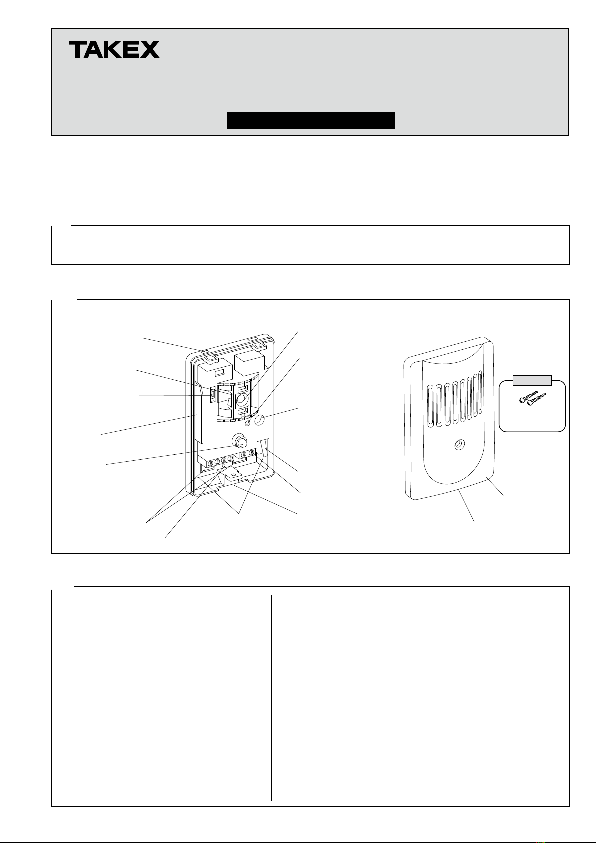
【Terminal arrangement】
Power (non-polarity)
9V to 30VDC 30mA
POWER COM N.C. TAMPER
Tamper (N.C.)
Opens when cover is detached
Alarm
Dry contact relay (N.C.)
Turn round when an alarm is initiated.
Capacity : 30V (AC/DC) 0.1A or less
Reset : approx. 2 sec.
【Allowable wiring distance between sensor and power source】
Size of wire used
AWG 22 (φ0.65mm)
AWG 20 (φ0.8mm)
AWG 18 (φ1.0mm)
Distance at 12VDC
250m (830 ft.)
450m (1460 ft.)
700m (2300 ft.)
The maximum wire length, when two or more units are
connected, is the above distance divided by the number of
units.
The protection circuit can be wired to a distance of max.
1,000m (3,300 ft) with AWG 22 (φ0.65mm) wire.
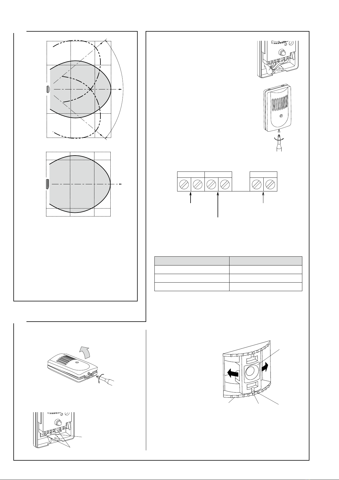
【Horizontal direction】
Use the Microphone holder to set a coverage that corresponds to
the installing position. (Adjustable by 40º)
(1) Installation
(2) Wiring
(3) Area setting
*The coverage indicated in the diagram does not
have surrounding walls or other objects that
would reflect ultrasonic waves, and the sensitivity
volume is turned all the way to H.
*Install the sensor so that sensor coverage could
cover all surface of protected window. For
reference, glass surface to be protected is 5m or
less square.
*Confirm the install position of the sensor and the
position of the surface of protected window.
Determine the optimal area angle, and use the
Microphone holder inside the sensor to set it.
Loosen cover locking screw to detach cover.
Check protection direction and install base on wall.
*Break knockouts and attach sensor with supplied
screws.
Connect as per wiring diagram 5. (2).
Set coverage and check operation.
Refer to 5. (3) Area setting and 6.
Operation check.
Replace cover and tighten cover locking
screw.
Rotate Microphone holder
to set area direction to
center of protected glass.
80°
(Area adjustable range)
[TOP VIEW]
6m [20ft]
3m [10ft]
3m [10ft]
6m [20ft]
4m [13ft]
3m [10ft]
3m [10ft]
4m [13ft]
8m
6m3m
[20ft][10ft] [26ft]
[SIDE VIEW] 8m
[26ft]
6m
[20ft]
3m
[10ft]
2 pitches 76mm (3") or
83.5mm (3.29") are available
for mounting hole.
Mounting hole.
Knockout
(Break with slender-driver)
Mark pitch by 10°
Microphone
holder
Center Direction of
area
⑤
①
②
③
④
Note 1)
2)
( )
6OPERATION CHECK
7OPERATION DESCRIPTION
EG-2000 operation
(Output selector "L")
Alarm generating sound
(EG-2000 operation Output selector "H")
Other device
activation
High sens.
47min. ON
3min. flashing
Low sens. Good sens. Success in noise test
Adjustment completed.
Environmental LED (Orange)
Environmental LED (Orange)
Alarm LED (Red)
Alarm output
Alarm LED (Red)
Alarm output
approx. 2 sec.
【Check mode】
Select "Check" mode for operation check and sensitivity adjustment.
In this mode, both environmental LED (Orange) and alarm LED (Red) activate.
【Operation mode】
When the unit has been activated the Alarm LED will flash for 3 minutes, and then it will remain constantly lit for
47 minutes.
This will enable identification of triggered devices in a multiple use scenario.
This can be manually reset either by interrupting the power supply or by switching the unit to "Check" mode, (please
note removal of cover will initiate tamper alarm).
Tamper function
This function is for detecting tampering or intentional removal of the cover. It detects the removal of the cover from the sensor
unit and outputs an alarm.
It is reset if the cover is returned to its original position, but check the operation of the sensor immediately if this situation
For precise operation, use EG-2000 (sold separately), and perform the following operation and sensitivity checks.
* Follow the EG-2000 instruction manual when performing these checks.
While checking that the sensor environmental LED lights ON, check the range of
the coverage and the optimal sensitivity.
Set the internal output switch of the EG-2000 to L for use.
①Supply power to the sensor with its cover removed, and select "Check" mode
with the mode switch.
Refer to 7. Operation description.
②First, begin activation by pressing the EG-2000 Send Button
near the sensor. Ensure that both the alarm LED (Red) and
the environmental LED (Orange) of the sensor are lit.
③From the surface of protected window, point the wave transmission part of the
EG-2000 at the sensor. Operate the equipment and check the sensitivity. Check
the sensitivity of the sensor at all positions at the surface of protected window.
Note: Some positions where light is reflected from ceilings, walls, and floors
make detection difficult for the EG-2000. Shift the position of the unit
slightly to the left or right. If only the environmental LED of sensor lights
ON, the sensor sensitivity is normal.
④Operate the sensor from the furthest point of required protection. Sensitivity is
correct when just the environmental LED lights. If neither alarm LED or
environmental LED light, then sensitivity is too low. If the alarm LED also
lights, sensitivity is too high. If sensitivity is not optimal in certain locations,
check the coverage again or adjust the sensor sensitivity by the sensitity volume.
⑤
If there is a possibility of sound or noise within
the same room, whether within or outside the
coverage, make some sound or noise and check
to make sure that the Environmental LED does
not light up. If it lights up from some sound or
noise, change the install position, or increase
the number of sensors, giving them each a
smaller range of coverage and lower sensitivity.
⑥After checking the sensitivity, set the mode
switch to operation mode, and then replace
the cover and tighten the cover lock screws.
①
Set the sensor mode
switch to Operation mode,
and check the operation of
the alarm.
②
From within the coverage
of the sensor, point the
wave
transmission
part of
the EG
-2000 at the sensor,
and operate by pressing
the send button. If the
sensor alarm LED is lit,
the operation of the sensor
alarm is correct.
Check the operation of the installed sensor.
Use for daily sensor operation checks and
during inspection ONLY.
Set the internal output switch of the EG-2000
to H for use.
Note: 1) A glass jar/bottle containing metal
coins can be used as a substitute for
the EG-2000.
Using 7 or more coins in a strong
sealed glass container, the shaking
of which replicates the EG-2000.
2)
This is an alternative method of testing
unit sensitivity and operational in the
absence of the correct equipment.
3) Obvious special care is needed if
this method is used as shaking to
vigorously may result in the glass
breaking and personal injury.
←
▼
▼
▼
▼
▼
▼
Sensitivity check
Alarm operation check
Retrigger 47min.
▼
Sensitivity is correct Sensitivity is too high
Lower the sensitivity
Environmental LED: OFF
Alarm LED: OFF
Environmental LED: ON
Alarm LED: OFF
Environmental LED: ON
Alarm LED: ON
Sensitivity is too low
Increase the sensitivity
Mode switch
Check
mode
Operation
mode
Environmental LED
Alarm LED
Environmental LED
Alarm LED
Environmental LED
Alarm LED
Alarm LED
Coverage
EG-2000


 User manual")