⑦
Vielen Dank, dass Sie sich für unsere ”intelligente”
Vierstrahl-Aktiv-Infrarotschranke entschieden haben.
Die Schranke zeichnet sich bei ordnungsgemäßer
Montage durch eine lange Lebensdauer und hohe
Zuverlässigkeit aus.
Damit Sie die Aktiv-Infrarotschranke richtig einsetzen
und optimal nutzen können, bitten wir Sie, diese
Anleitung sorgfältig durchzulesen.
Produktbeschreibung
Bezeichnung der Teile
1
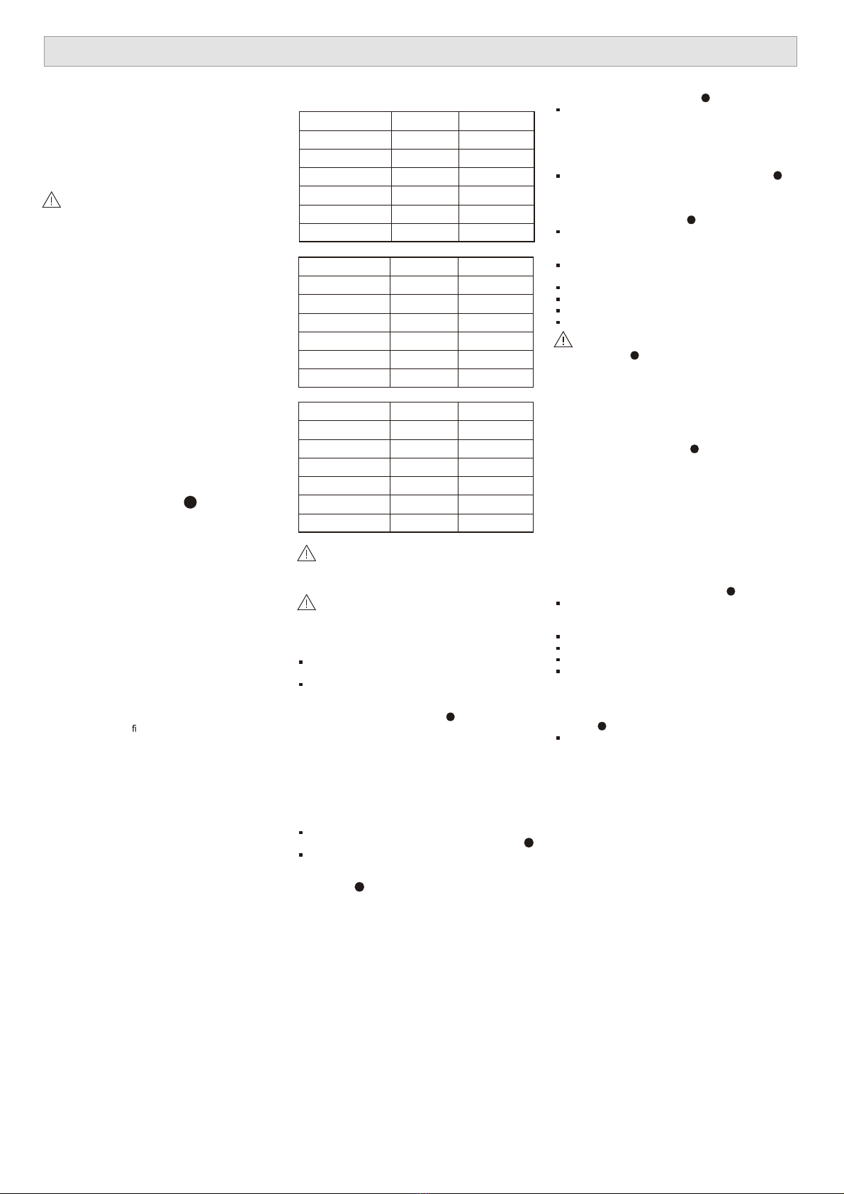
Leitungsabstand zwischen Infrarot-
schranken und Einbruchmeldezentrale
Installationshöhe
In den meisten Fällen ist es sinnvoll, den Strahl auf
einer Höhe von 70 bis 90cm zu installieren.
Beachten Sie die Strahlenausdehnung der einzelnen
Modelle, um eine eventuelle Reflexion auf dem
Untergrund oder auf in der Nähe stehenden Objekten
auszuschließen (siehe Tabelle
3
).
Montage
Die Schranken können einfach auf einem Mast oder
einer ebenen Oberfläche montiert werden.
- Ausrichtung über Drehspiegel
Über die Einstellscheibe und die Einstellschrauben
kann sich der Spiegel horizontal (±90°) und vertikal
(±10°) bewegen; dadurch ist ein Betrieb der
Schranken in alle Richtungen möglich.
Entfernen Sie die Abdeckung, indem Sie die
Schraube am unteren Teil der Abdeckung lösen.
6
E
Lösen Sie die Schrauben, mit denen die Schranken-
einheit auf der Montageplatte befestigt ist und lösen
Sie die Montageplatte, indem Sie sie nach unten
schieben.
6
B
Wandmontage
Bohren Sie Löcher in die Wand.
4
A
Setzen Sie die Montageplatte als Bohrschablone auf
die Wand und markieren Sie die Position der
Bohrlöcher. (Lassen Sie eine Fläche von 20mm
oberhalb und 25mm unterhalb der Platte frei.
Dadurch kann die Geräteabdeckung nach der
Montage leichter abgenommen werden.)
Führen Sie Vorbohrungen an der Wand durch.
4
B
Holzwand: 3mm Durchmesser.
Betonwand: Richten Sie sich nach den für den
verwendeten Dübel geltenden Angaben.
Installieren Sie die Schranke
4
C
Stecken Sie die Montageschrauben in die Bohrungen,
wobei ein 15 mm langes Stück der Schraube stehen
bleiben sollte.
Bringen Sie die Montageplatte auf den aus der Wand
ragenden Schrauben an.
Ziehen Sie die Leitung durch.
Ziehen Sie die Schrauben an.
Schließen Sie die Anschlussklemmen an.
Bringen Sie die Schrankenabdeckung an.
Schliessen Sie die Öffnung der Leitungs-
durchführung, um ein Eindringen von Insekten zu
vermeiden.
4
C
Die Schranke kann nicht in einer Installationsdose
installiert werden.
Für die Zuleitungen ist die Verwendung einer
Installationsdose jedoch möglich.
Mastmontage
Bringen Sie eine Leitungsdurchführung am Mast an.
Ziehen Sie die Leitung durch.
5
A
- Das Gerät kann auf einem Mast mit einem
Außendurchmesser von 38 bis 45mm montiert
werden.
- Bringen Sie an der Stelle des Mastes, an der die
Schranke angebracht werden soll, ein Loch mit
einem Durchmesser von 13mm für die Zuleitungen
an.
Entfernen Sie um die Öffnung herum alle Bohrspäne
und scharfen Kanten mit einer Feile, um eine
Beschädigung der Kabel zu verhindern.
Auch eine Gummidurchführung kann verwendet
werden, wenn dies gewünscht wird.
Montieren Sie die Schranke am Mast.
5
B
Bringen Sie die U-Klammern am Mast an und
befestigen Sie sie mit Schrauben an der
Montageplatte.
Befestigen Sie die Schrankeneinheit.
Ziehen Sie die Leitung durch.
Schließen Sie die Anschlussklemmen an.
Bringen Sie die Abdeckungen an. (Brechen Sie die
gestanzten Öffnungen an der Schrankenabdeckung
und der Mastabdeckung entsprechend dem
Mastdurchmesser und der Mastanordung auf.)
Schrankenanordnung Rückseite an Rückseite am
Mast
5
C
Bringen Sie an den Masten vier U-Klammern zu je
zwei Paaren an, ein Paar jeweils oberhalb des
anderen, ausgerichtet in die entgegen gesetzte
Richtung (siehe Abbildung).
Montageanleitung PB-50FA / PB-100FA / PB-200FA
Die Schranke ist dafür bestimmt, unbefugtes Eindringen
festzustellen und einen Alarm auszulösen; es handelt
sich dabei nicht um eine einbruchhemmende Vorrichtung.
TAKEX übernimmt keine Haftung für Schäden oder
Verletzungen, die durch Unfall, Diebstahl, höhere Gewalt
(einschließlich Überspannungen durch Blitzschlag),
Missbrauch, falschen Gebrauch, unsachgemäßen Gebrauch,
falsche Montage oder fehlerhafte Wartung entstehen.
Die Aktiv-Infrarotschranke von TAKEX (PB-50FA,
PB-100FA und PB-200FA) besteht aus einem
Infrarotsender und –empfänger.
Die Schranke ist für eine UND-Schaltung ausgelegt – ein
Alarm wird nur dann ausgelöst, wenn die vier (übereinander)
angeordneten Strahlen gleichzeitig unterbrochen werden.
Es wird kein Alarm ausgelöst, wenn Insekten oder fallende
Blätter nur bis zu drei Strahlen unterbrechen.
Darüber hinaus kann zwischen vier
Durch die programmierte automatische
Verstärkungsregelung wird die Empfindlichkeit bei
schlechtem Wetter automatisch erhöht; Nebel, Regen oder
Frost stellen für die Aktiv-Infrarotschranke deshalb kein
Problem dar.
PB-50FA 12V 24V
AWG20 (ø0.8 mm) 244m 1,710m
AWG18 (ø1.0 mm) 381m 2,680m
AWG17 (ø1.1 mm) 457m 3,200m
AWG16 (ø1.25 mm) 595m 4,000m
AWG15 (ø1.4 mm) 750m 5,180m
AWG14 (ø1.6 mm) 976m 6,860m
PB-100FA 12V 24V
AWG20 (ø0.8 mm) 200m 1,550m
AWG18 (ø1.0 mm) 335m 2,410m
AWG17 (ø1.1 mm) 400m 2,930m
AWG16 (ø1.25 mm) 534m 3,660m
AWG15 (ø1.4 mm) 670m 4,730m
AWG14 (ø1.6 mm) 884m 6,000m
PB-200FA 12V 24V
AWG20 (ø0.8 mm) 192m 1,340m
AWG18 (ø1.0 mm) 300m 2,100m
AWG17 (ø1.1 mm) 366m 2,560m
AWG16 (ø1.25 mm) 473m 3,200m
AWG15 (ø1.4 mm) 595m 4,000m
AWG14 (ø1.6 mm) 777m 5,340m
Sind zwei oder mehr Schrankenpaare miteinander
verbunden, entspricht der maximale
Leitungsabstand dem oben angegebenen Wert geteilt
durch die Anzahl der Schrankenpaare.
Die Signalleitung kann mit I-Y(ST)Y Telefondraht
(Durchmesser 0.65mm) bis zu einem Abstand von
1,000m verlegt werden.
A - Abdeckung
B - Sucher
C - Spiegel
D - Einstellschraube für horizontale Feineinstellung
E - Einstellschraube für vertikale Ausrichtung
F - Anschlussklemmen
G - Schalter für Sabotageanzeige
H - Schlossschalter für die automatische
Verstärkungsregelung (nur Empfänger)
I - Funktionserklärungen (siehe R)
J - Spiegel
K - Einstellscheibe
L - Dämpfungsscheibe
M - Montageplatte
N - Befestigungsschelle
O - Vorgestanzte Öffnung
P - Abdeckung für Mastmontage
Q - Vorgestanzte Öffnung
R - Betriebsanzeige
S - Anzeige für Emp ndlichkeitsdämpfung
T - Alarmanzeige
U - Schalter für akustisches Ausrichtungssignal
(werkseitig auf OFF eingestellt)
V - Einstellung der Ansprechzeit (werkseitig auf 0,05
Sekunden eingestellt)
W - Buchse für Testgerät
X - Speicheranzeige-LED
Y - Einstellung für Alarmausgang (werkseitig auf N/C
eingestellt)
Z - Einstellung für Speicher (werkseitig auf AUS
eingestellt)


 User manual")