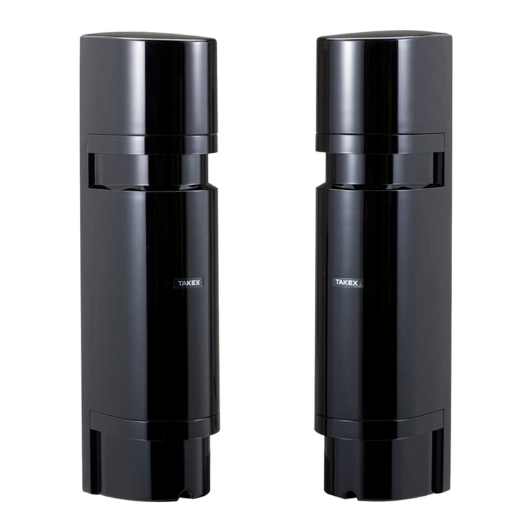
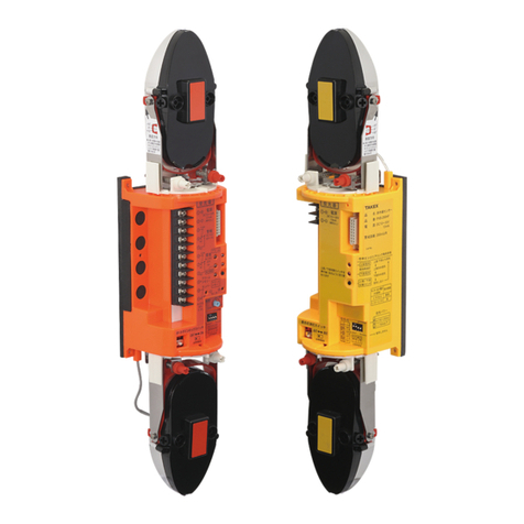
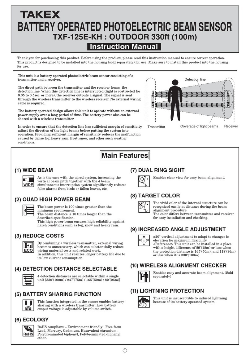
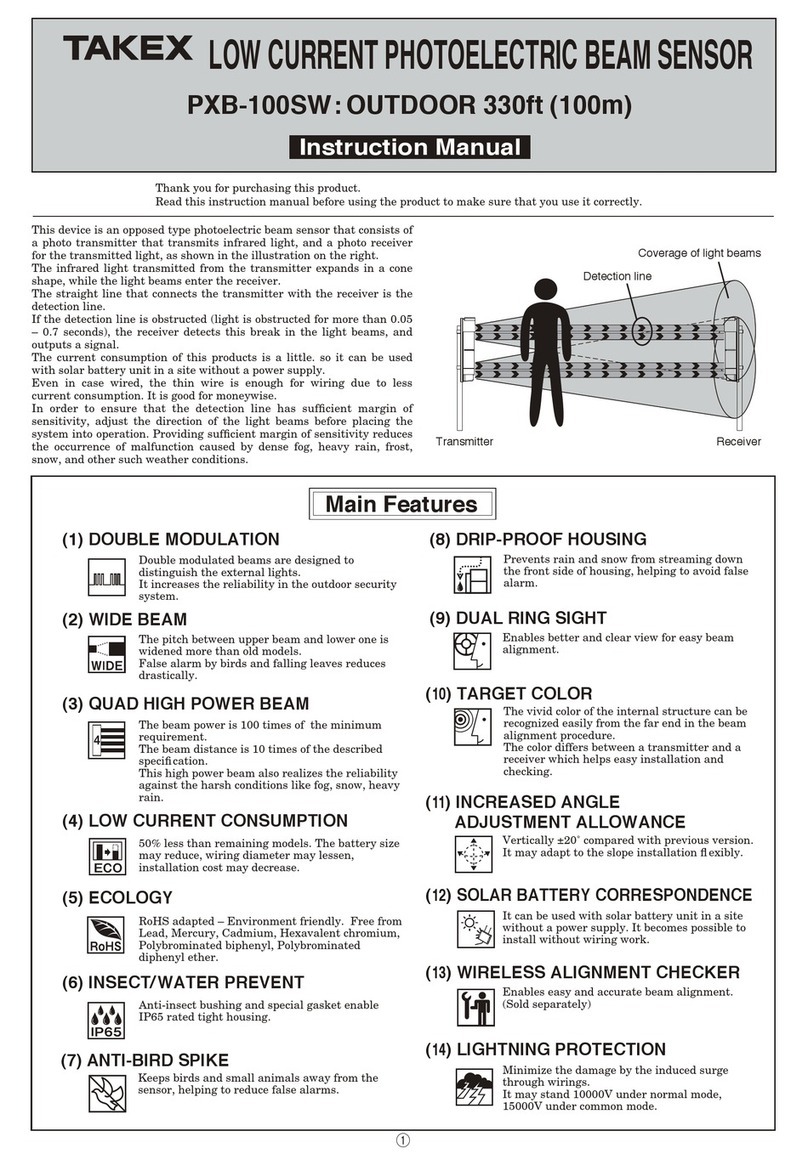
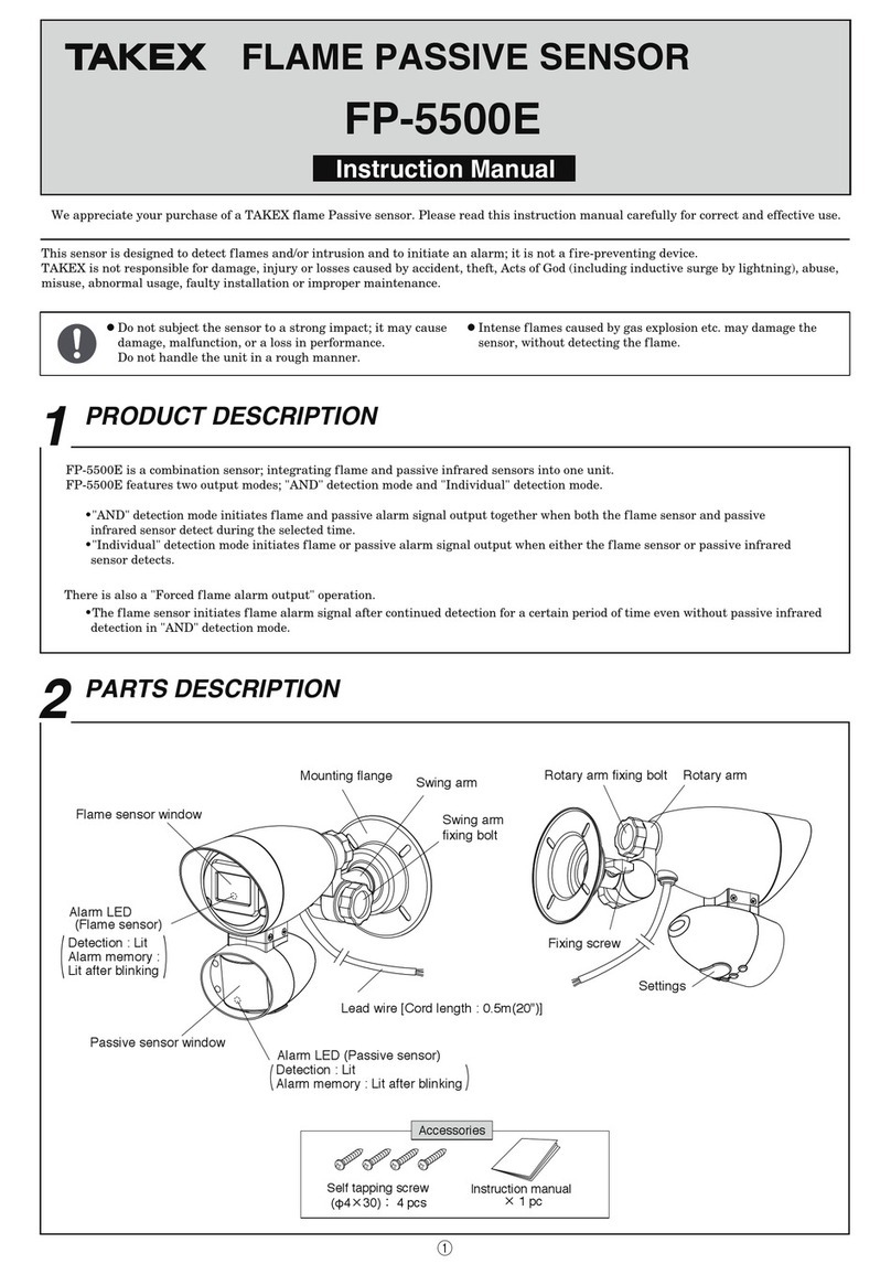
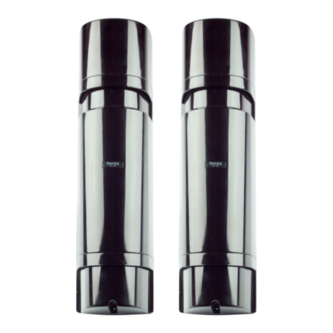
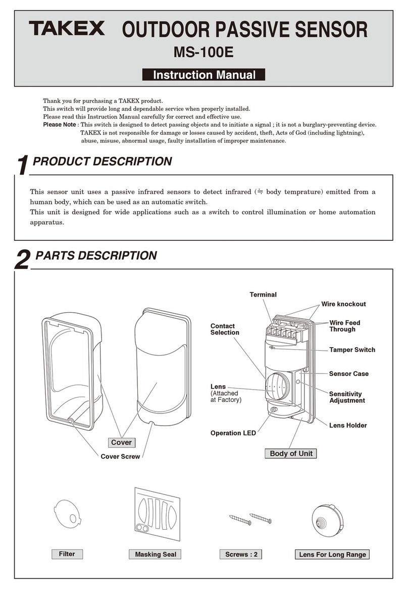
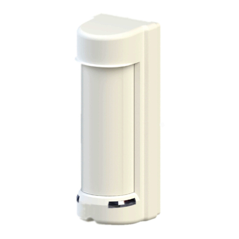
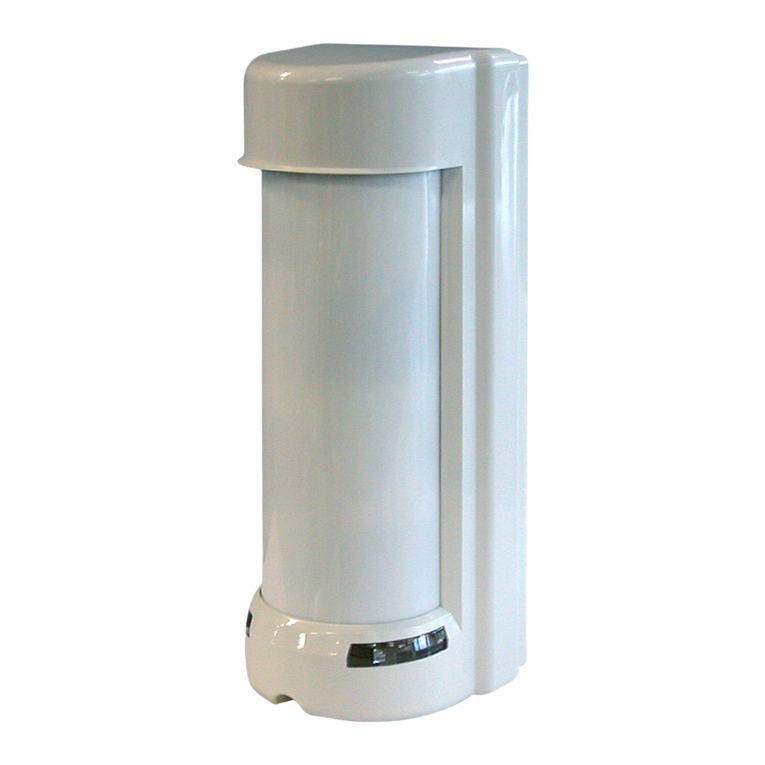
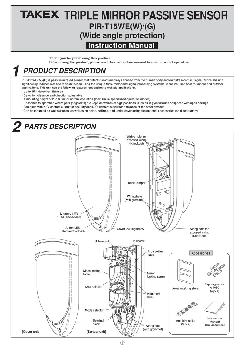
Takex PB-100AT-KH User manual


1) DO'S AND DON'T'S 2) Protection distance
2CAUTIONS ON INSTALLATION
・Do not install the unit on
places where it may be
splashed by dirty water or
direct ocean spray.
・Do not install the unit on
unsteady surfaces.
・Do not install the unit at places
where it may be interrupted by
obstacles such as trees.
・Avoid strong light from the
sun, automobile headlights
etc. shining on transmitter
and receiver directly. (Avoid
light within ±2°degrees of
optical axis.)
1)Basic connection
The equipment must be powered from an LPS in accordance with EN60950-1 : 2001
2
)
When two or more sensors are
connected to the same line.
3)When two or more sensors are
connected to separate lines.
Power
(DC12V)
Power
(DC12V)
Power
(DC12V)
Alarm signal
(N.C.)
Alarm signal
(N.C.)1
Alarm signal
(N.C.)2
Alarm signal
(N.C.)
(Control panel)(Control panel)
(Control panel)
}
}
1
1234
2
Wiring
}
}
1
121234 1234
2
}
}
}
1
121234 1234
2
TR RE TR RE TR RE TRRE
TRRE
Maxprotectiondistance
330'(100m)
8'(2.4m)
Viewfinder
TR
RE
1PARTS DESCRIPTION
Mirror
Horizontal angle
adjuster
Vertical angle
adjuster
Terminals
Gain lock switch
(Receiver only)
Indication panel
Mirror
TR : Shading plate
RE : Shading plate +
sensitivity checker
Adjustment dial
[Transmitter]
[Receiver]
Operation LED
Beam power
(H set at factory)
Beam channel frequency
selectable switch
(frequency 1-4)
(1CH. set at factory)
Sensitivity attenuation
LED
Beam channel
(frequency 1-4)
(1CH. set at factory)
Beam selector
(upper set at factory)
Response time
adjustment〔OR〕
(0.1sec. set at factory)
Environmental output
terminal
Alarm LED
Beep (Alignment tone)
switch
(OFF set at factory)
Response time
adjustment〔AND〕
(0.035sec. set at factory)
Monitor jack
Functions / Indcations
●Panhead screw
(M3×12)8
●Lock spacer1
Accessories
②

Mounting
●Install the unit to a beam tower.
Some towers could block the beam within its
case when the mirror is turned by ±90°
vertically.
Please refer to the instruction manual of the
beam tower carefully before use.
●Beam sensor's reecting mirror can be moved
horizontally (±90 degrees) and vertically
(±10 degrees) allowing the unit to work in all
directions.
±10°
±90°
90°
Power
(12VDC)
Alarm
Control panel
6) Wiring Distance between sensor and control panel.
3. Terminal arrangement
When using this product in a Mercantile Burglar
Alarm, UL681, tamper switch should be connected
to a 24 hour supervisory loop.
●
Standby battery
Be sure the control panel is equipped with
adequate standby battery and charging circuit.
Use 12V (at least) Nicd or lead acid battery
with minimum capacity of 0.5AH.
*
Max. wiring distance when two
or more sets are connected is
the above value divided by the
number of sets.
Note 1)
The signal line can be wired to
a distance of up to approx.
3300' (1000m) with AWG 22
(Dia. 0.65mm) telephone wire.
Note 2)
Unit should be connected to a listed, class 2
power source capable of providing standby
power for a minimum of 4 hours.
●
Estimated battery life
AWG20 (Dia.0.8mm)
AWG18 (Dia.1.0mm)
AWG17 (Dia.1.1mm)
AWG16 (Dia.1.25mm)
AWG15 (Dia.1.4mm)
AWG14 (Dia.1.6mm)
630' (192m)
1000' (300m)
1200' (366m)
1550' (473m)
1950' (595m)
2550' (777m)
4400' (1340m)
6900' (2100m)
8400' (2560m)
10500' (3200m)
13500' (4000m)
17500' (5340m)
wire size voltage 12V DC 24V DC
No. of
pair
Md AA
0.5AH
Gel Cell
5.0AH
Gel Cell
1.0AH
1
2
4
8
5 hr
11 hr
5 hr
58 hr
29 hr
14 hr
7 hr
[Transmitter] [Receiver]
Power
10V to 30V DC
(Non-polarity)
1
2
Power
10V to 30V DC
(Non-polarity)
1
2
Alarm output Form C
30V AC/DC 1A or less
COM
NO NC
Environmental Form C
30V AC/DC 1A or less
COM
NC
NO
3
4
5
10
8
9
③
4) 2-stacked standard connection. 5) When environmental module is used.
Note) Refer to 5. FUNCTIONS DESCRIPTION
for beam channel (beam frequency selection).
[Cautions on wiring]
●
●
TR. RE.
TR. RE.
Power (12VDC)
Alarm
Contorol panel
}
}
Tamper (1b)
}
Environmental signal (1C)
}
1
1 2 34
2
(CH.1)
(CH.3)
}
}
1
1234
2
1
1 2 34
2
67
8 9
10
67
Signal output on receiver can not be used independently for the upper /
lower optics, only as a set.
Outdoor wiring should be in PVC if below ground or use direct burial
cable. Conduit should be used for above ground wiring.


1CH 2CH 3CH 4CH
1)Line protection
1
CH
TR 1
CH
RE
3
CH
TR 3
CH
TR
3
CH
RE 4
CH
TR 4
CH
RE
3
CH
RE
1
CH
TR 1
CH
RE
1
CH
RE
3
CH
RE
2
CH
RE
4
CH
RE
2
CH
RE
4
CH
RE
1
CH
RE
3
CH
RE
2
CH
TR 2
CH
RE
1
CH
TR 3
CH
TR
1
CH
RE
1
CH
TR
1
CH
RE
1
CH
TR
1
CH
TR
1
CH
TR 2
CH
TR
3
CH
TR 4
CH
TR
2
CH
TR 1
CH
TR
4
CH
TR 3
CH
TR
3
CH
TR 1
CH
TR
3
CH
TR
1
CH
RE
1
CH
RE
3
CH
RE
3
CH
RE
1
CH
RE
3
CH
RE
3
CH
TR 3
CH
RE
2)2-stacked protection
3)Line and 2-stacked protection
4)Perimeter protection
5)Perimeter double stacked protection
5FUNCTIONS DESCRIPTION
1. Four channel frequency selection
The combination of 1CH and 3CH or 2CH and 4CH (do not use adjacent channels) are recommended to avoid crosstalk between
units which are stacked, in-line, or other congulations which have the potential of spill-over transmission from one beam to
another. Set the frequency level as illustrated.
MAKE SURE TRANSMITTER AND RECEIVER OF
PAIR ARE SET AT SAME CHANNEL ! Paired TR/RE
will not set up unless set at the same channel.
2. Beam power selection 3. Auto-gain lock function
This option allows eld selection of the appropriate
beam intensity relative to the application. For distance
signicantly less than the specied protection distance,
the beam intensity should be reduced to eliminate
potential reection problems. For zones reaching
maximum protection distance, the beam level should be
set to the highest level.
[Note]
The use of a voltmeter for alignment is advised to
ensure highest level of stability.
Consult with TAKEX distributor or TAKEX regional
ofce about the frequency selection for installations
not mentioned in this instruction manual. Inappro-
preate choice of frequency may cause malfunction.
Do not fail to use PB-IN-100HF in combination with
PB-IN-HF series when stacked installed (same
directional transmission). The other models may
cause malfunction.
Note : For interior applications where greater chance for
reection occurs, the setting should be at LOW.
The auto-gain lock serves to standardize the responsiveness
and tolerance level of the units regardless of varying
distance in an installation.
The situations above have exactly the same tolerance and
responsiveness levels even though the distance are different.
L
H
L
H (set at factory)
250' (75m) or less
Over 250' (75m) to 330' (100m)
Less than protection
distance
Max. protection distance
1)
⑤

4. Tone indicator
2) A "beep" tone is issued from the receiver approximately 5 seconds after the lock spacer is inserted into position.
This tone indicates the Auto-gain has been set. Refer to the chart below.
Note 1)
2)
3)
A tone is generated regardless of whether "beep" (alignment tone) switch is set to ON or OFF.
The auto-gain setting is locked in for approximately two weeks even if power is disrupted.
If the lock spacer is detached while power is supplied or if power is discontinued for longer than two weeks
(but cover left in place), the auto-gain automatically reset to maximum sensitivity. (Gain is automatically locked
with power re-supplied.)
This feature provides audible testing or signals for the following items.
5. Response time changeover function
(Dual response time system)
And-gated response time and OR-gated response time can
be set separately.
1) An object passing through the beams faster than the set
response time is undetected.
2) Adjust response time a little slower where the units may
be affected by many birds.
Note) Set And-gated response time shorter (faster) than
Or-gated response time.
6. Environmental Module
The environmental signal is initiated if the beam reception
level is reduced to approx 25% or less.
The module "Watches" for a gradual degradation of the
beam reception which is indicative of extremely poor
weather conditions.
7. Beam selector
Use when beam alignment is adjusted.
Only the beam reception level of the beam that is selected
by the beam selector is indicated on sensitivity attenuation
LED, Sound check tone and monitor output.
When a lock spacer is inserted this function is canceled and
sensitivity attenuation LED lights regardless of positioning
of the selector even when either side of beam is attenuated.
Tone Indicates Result Cause Remedy
Optimal sensitivity has
been set.
One pulse
(Beep)
OK
Continuous
tone (20
seconds)
Optimal sensitivity can
not be set.
NG 1. Beam is interrupted when a lock spacer
is inserted.
2. Beams are mis-aligned and sensitivity
attenuation LED lights.
1. Remove any blockage items or ensure
hand is not breaking beam and insert a
lock spacer again.
2.
Check beam power setting at transmitter
with cover off and re-adjust beam
alignment.
Test / Signal Beep switch Other condition Description
Reception strength monitored. Tone pitch increases as reception
improves.
(Note : No tone is given if sensitivity attenuation LED is lit or
if receiver cover is attached.)
●
Beam alignment ON Lock spacer detached.
For approx. 5 min.
after gain is locked.
Tone is linked to alarm LED. Both trip simultaneously.
●
About 5sec. after the
lock spacer is inserted
Short tone indicates lock is set.
Continuous tone (20sec.) indicates readjustment.
●
ON
ON or OFF
Walk test
Auto-gain lock
Upper Lower
(Set at factory)
→
→
And-gated (all beams interruption)
0.3
0.4
0.5 (sec.)0.035
0.1
0.2
(Set at factory)
Response time adjustment (And)
Or-gated (either side beams interruption)
SW
Response time adjustment (Or)
Response
time 0.1 0.2 0.3 0.5
Run at full speed
Walk with quick steps
Crawling
Response : 0.05sec. Response : 0.3sec. Response : 0.5sec.
(Set at factory)
(sec.)
⑥

6TROUBLESHOOTING
7SPECIFICATIONS
Symptom Possible cause Remedy
Operation LED does not
light
1. Disruption of power or inadequate power
2. Bad wiring connection or broken wire, short
1. Correct power source
2. Check and correct wiring
1. Disruption of power or inadequate power
2. Bad wiring connection or broken wire, short
3. Reection of beam is ooding receiver and sent into
the receiver
4. Beam interruption time is shorter than response
time
1. Correct power source
2. Check and correct wiring
3. Remove reecting object. Set beam power to Low.
Contact Pulnix for further remedies
4. Adjust response time
Receiver Alarm LED
does not light when the
beam is broken
Receiver Alarm LED
stays lit
1. Alignment is off
2. Shading object between transmitter and receiver
3. Optics of units are soiled
4. Frequency channel setting on transmitter does not
match with that on receiver
1. Check and adjust
2. Check site / remove any possible obstacles
3. Clean the optics with a soft cloth
4. Readjust to be the same channel
1. Bad wiring connection
2. Change of supply voltage
3. Shading object between transmitter and receiver
4. The wiring of power machine is located nearby
transmitter and receiver
5. Unstable installation of transmitter and receiver
6. Optics of units are soiled
7. Improper alignment
8. Small animals may pass through the 4 beams
9. Beam power switch is set at L, which does not keep
enough sensitivity allowance
1. Check again
2. Stabilize supply voltage
3. Remove the shading object
4. Change the place for installation
5. Stabilize
6. Clean the optics with soft cloth
7. Check and re-adjust
8. Change environments or the place for installation
9. Set beam power switch at H and make the unit
gain-locked with receiver cover detached
Intermittent alarm
(Units should be tested on a regular weekly basis)
Model
Detection system
Infrared beam
Protection distance
Max. arrival distance
Responce time
Power supply
Current consumption
Alarm output
Environmental output
Alarm LED
Sensitivity attenuation LED
Functions
Beam adjustment
Ambient
temperature range
Mounting position
Wiring
Weight
Appearance
PB-100AT-KH
Near infrared beam interruption system
(TR,-RE 4 beams simultaneous interruption or upper 2 beams interruption or
lower 2 beams interruption)
Double modulation pulsed beam by LED
Outdoor 330' (100m) or less
Tenfold 3300' (1000m)
Dual response time system 0.035-0.5sec. (AND gated) 0.1, 0.2, 0.3, 0.5sec.
(OR gated)
10V to 30V DC (non-polarity)
85mA or less at protection (Max. 120mA or less)
Dry contact relay 1c
Reset : Interruption time + off-delay (approx. 1.5 sec.)
Contact capacity : 30V AC / DC, 1A or less
Dry contact relay : 1c
Contact operation : Output when weather condition gets worse
Contact capacity : 30V AC / DC, 1A or less
Red LED (receiver) lights when an alarm is initiated
Red LED (receiver) lights when beam reception is attenuated
Modulated beam frequency selection, Tone indicator, Environmental module,
Beam power selection, Beam selector, Programmed AGC. Auto-gain lock function,
Monitor jack.
Horizontal : ±90°, Vertical : ±10°
−31°F to +151°F (−35℃to +66℃)
Beam tower
Terminals
Transmitter : 10.6 oz (300g)
Receiver : 14.1 oz (400g)
ABS resin
⑦
⑧
InJapan
Takex America Inc.
Unit 16/35 Garden Road, Clayton,
3168 Victoria, Australia
Tel : 03-9546-0533
Fax : 03-9547-9450
Takenaka Engineering Co., Ltd.
83-1, Gojo-sotokan, Higashino,
Yamashina-ku, Kyoto 607-8156, Japan
Tel : 81-75-501-6651
Fax : 81-75-593-3816
http : // www. takex-eng. co. jp /
Takex America Inc.
230E, Caribbean Drive
Sunnyvale, CA 94086, U.S.A.
Tel : 408-747-0100
Fax : 408-734-1100
http : // www. takex. com
Takex Europe Ltd.
Takex House, Aviary Court, Wade Road,
Basingstoke, Hampshire. RG24 8PE, U.K.
Tel : (+44)01256-475555
Fax : (+44)01256-466268
http : // www. takexeurope. com
IntheU.S. IntheU.K.
InAustralia
EXTERNAL DIMENSIONS
8
SPECIAL NOTES
9
This equipment has been tested and found to comply with the limits for a Class B digital device, pursuant to part 15 of the FCC
Rules. These limits are designed to provide reasonable protection against harmful interference in a residential installation. This
equipment generates, uses and can radiate radio frequency energy and, if not installed and used in accordance with the instructions,
may cause harmful interference to radio communications. However, there is no guarantee that interference will not occur in a
particular installation. If this equipment does cause harmful interference to radio or television reception, which can be determined by
turning the equipment off and on, the user is encouraged to try to correct the interference by one or more of the following measures :
---Reorient or relocate the receiving antenna. ---Increase the separation between the equipment and receiver. ---Connect the equipment
into an outlet on a circuit different from that to which the receiver is connected. ---Consult the dealer or an experienced radio / TV
technician for help.
WARNING : Changes or modications not expressly approved by the party responsible for compliance could void the user's authority
to operate the equipment.
Limited Warranty :
TAKEX products are warranted to be free from defects in material and workmanship for 12 months from original date of shipment. Our warranty does not cover damage or
failure caused by Acts of God (including inductive surge by lightning), abuse, misuse, abnormal usage, faulty installation, improper maintenance or any repairs other than
those provided by TAKEX. All implied warranties with respect to TAKEX, including implied warranties for merchantability and implied warranties for tness, are limited in
duration to 12 months from original date of shipment. During the Warranty Period, TAKEX will repair or replace, at its sole option, free of charge, any defective parts
returned prepaid. Please provide the model number of the products, original date of shipment and nature of difculty being experienced. There will be charges rendered for
product repairs made after our Warranty period has expired.
No.05-626 1110
MOUNT HOLE
13.78"(350mm)
3.46"(88mm)
2.36"(60mm)
2.83"(72mm)
4-φ0.12"(φ3mm)
5.12"(130mm)
Table of contents
Other Takex Security Sensor manuals

Takex
Takex PR-5B User manual

Takex
Takex SSP-S200 Series User manual

Takex
Takex TXF-125-KH User manual

Takex
Takex PB-30SU User manual

Takex
Takex PIR-T15WE(W) User manual

Takex
Takex MX-12FAM User manual

Takex
Takex Quad PB-IN-50HF User manual

Takex
Takex PA-5312E User manual

Takex
Takex MS-100E User manual

Takex
Takex MS-12 Series User manual
Popular Security Sensor manuals by other brands

Aritech
Aritech GS620N installation manual

New Focus
New Focus 1480 user guide

Menvier
Menvier 800 Series quick start guide

Online Electronics
Online Electronics ID5000P operating manual

Nivel System
Nivel System CLS-3 user manual

Homematic IP
Homematic IP HmIP-SMI55-2 Mounting instruction and operating manual