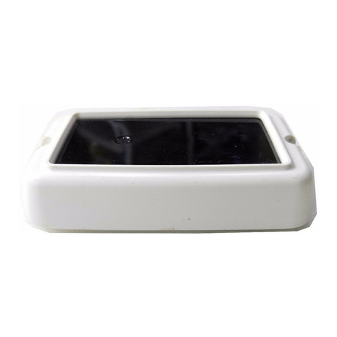
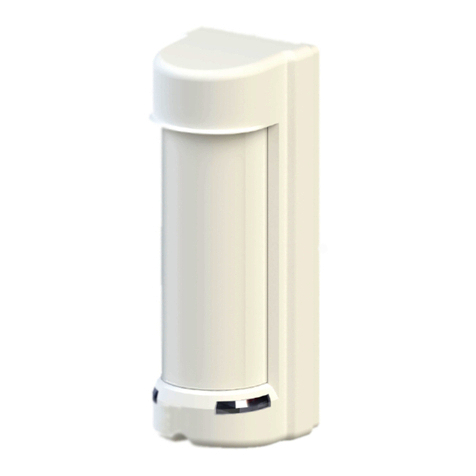
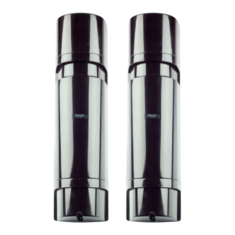
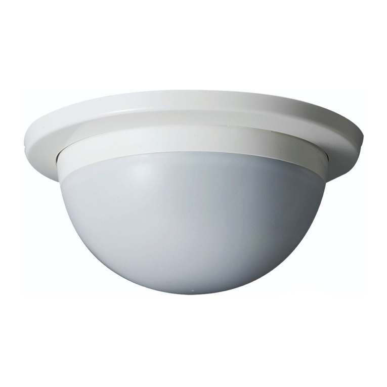
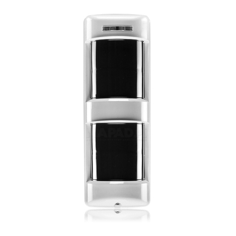
Takex FP-5500E User manual

①
Instruction Manual
FLAME PASSIVE SENSOR
)3(
We appreciate your purchase of a TAKEX flame Passive sensor. Please read this instruction manual carefully for correct and effective use.
● ● Intense
f
lames caused by gas explosion etc. may damage the
sensor, without detecting the flame.
Do not subject the sensor to a strong impact; it may cause
damage, malfunction, or a loss in performance.
Do not handle the unit in a rough manner.
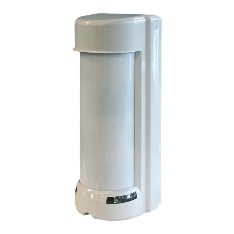
FP-5500E is a combination sensor; integrating flame and passive infrared sensors into one unit.
FP-5500E features two output modes; "AND" detection mode and "Individual" detection mode.
There is also a "Forced flame alarm output" operation.
s
"AND" detection mode initiates
f
lame and passive alarm signal output together when both the
f
lame sensor and passive
infrared sensor detect during the selected time.
s
"Individual" detection mode initiates
f
lame or passive alarm signal output when either the
f
lame sensor or
passive infrared
sensor detects.
s
The
f
lame sensor initiates
f
lame alarm signal after continued detection for a certain period of time even without passive infrared
detection in "AND" detection mode.
This sensor is designed to detect flames and/or intrusion and to initiate an alarm; it is not a fire-preventing device.
TAKEX is not responsible for damage, injury or losses caused by accident, theft, Acts of God (including inductive surge by lightning), abuse,
misuse, abnormal usage, faulty installation or improper maintenance.
5RWDU\DUP5RWDU\DUPIL[LQJEROW
6ZLQJDUP
IL[LQJEROW
)L[LQJVFUHZ
6ZLQJDUP
0RXQWLQJIODQJH
)ODPHVHQVRUZLQGRZ
$ODUP/('
)ODPHVHQVRU
3DVVLYHVHQVRUZLQGRZ
/HDGZLUH>&RUGOHQJWKP@
6HWWLQJV
'HWHFWLRQ/LW
$ODUPPHPRU\
/LWDIWHUEOLQNLQJ
'HWHFWLRQ/LW
$ODUPPHPRU\/LWDIWHUEOLQNLQJ
( )
( )
6HOIWDSSLQJVFUHZ
Ѯ×:SFV
$FFHVVRULHV
,QVWUXFWLRQPDQXDO
×SF
352'8&7'(6&5,37,21
3$576'(6&5,37,21
$ODUP/('3DVVLYHVHQVRU

②
%HVXUHWRREVHUYH
Strictly observe the specified voltage (10 to 30V DC).
:DUQLQJ This indicates the possibility of severe injury, even death, if ignored or a user handles the unit incorrectly
&DXWLRQ
:DUQLQJ
Do not disassemble or alter this product. Do not touch the wiring leads with wet hands.
Do not connect devices which exceed the capacitance of
this sensor.
A prohibited action, you must not do.
An action you must do, and information you should keep in mind.
This indicates the possibility of minor injury and/or damage to properties, or of a notification delay in your
system due to false operations and/or non-detection, if ignored or a user handles the unit incorrectly.
&DXWLRQ
If the following events occur, turn off the power of the unit
immediately, and ask the place of purchase for repair.
Failure to follow this may result in fire, electric shock, and/or
malfunction.
・Smoke, abnormal odor, and/or sound are found
・
Liquid, such as water, and/or foreign material has entered the
unit
・
The unit has deformed and/or damaged parts
Do not apply impact to the unit. Strong impact may result in
performance deterioration and/or damage to the unit.
The unit may not operate properly near the devices that generate
a strong electric or magnetic field. Also, the devices near the unit
may not operate properly due to the magnetic field and/or
magnetism generated by the unit. Make sure to confirm before
operation.
Make sure to perform a sufficient operation check on the
whole system before operation.
Never touch the detection element with your bare hands. If it
gets dirty with oil from your hands, the sensitivity will
decrease.
This sensor detects ultraviolet rays contained in
f
lames and
outputs a signal. It is not a
f
ire-
f
ighting device (
f
ire alarm,
detector for fire alarm system) and does not detect smoke or
heat that does not contain ultraviolet rays. Please note that we
are not liable for any accidents caused by
f
ire, personal injury,
and disaster, mistakes in equipment usage, inadequate
maintenance and inspection, natural disasters (including
induced lightning surges), etc.
Do not install this device in a location that cannot support its
weight. This may cause the device to fall and cause an injury
or malfunction of the device.
Mount the unit on wall surfaces where reinforcement materials
are used. If you mount the unit on non-wood materials such as
plaster board or concrete, surely mount it using anchors and
mounting screws that match the wall materials. Unstable
mounting may result in injury and/or property damage if the
unit falls
Do not install the unit in locations where sparks or flames are
usually used (kitchen, incinerator, etc.).
Do not install the unit in locations subject to severe shock or
electric noise.
Do not install the unit in locations where a shield object (glass,
transparent resin, etc.) is in front of the sensor.
Do not install the unit near high voltage power lines. Sparks
from pylons may cause false detection.
Do not install the unit near railways. Sparks from pantographs
may cause false detection.
Be sure to install the unit downward from horizontal.
Keep the detection window straight and the setting section at
the bottom.
35(&$87,216

③
'HWHFWLRQDUHD $QJOHDGMXVWPHQW
(SLWFK)
٘VWHS
(SLWFK)
①
②
③
)ODPHRIJDVOLJKWHU
〔$SSUR[FPµ〕
3DVVLYHVHQVRUDUHD
P
P
P
P
P
)ODPHRIQKHSWDQH
RQFPµ
VTXDUHSDQ
〔)ODPHKHLJKW
DERXWFPµ〕
)ODPHRIQKHSWDQH
RQFPµ
VTXDUHSDQ
〔)ODPHKHLJKW
DERXWFPµ〕
3DVVLYHVHQVRUDUHD
P
P
(VWHS)
P
P
P
P
)ODPHRIJDVOLJKWHU
〔$SSUR[FPµ〕
Three-part rotation mechanism, as shown below, enables
adjustment in various angles. Adjustable angles may be
limited depending on mounting location and change
mounting way if necessary.
* For outdoor application, be sure to adjust the detection
area downward to avoid the influence of sunlight and
the detection of unexpected objects in the distance.
①Loosen the fixing screw
and remove the mounting
flange from the main body.
④Slightly loosen the rotation fixing bolt, swing fixing
bolt, and mounting fixing screw to determine the
direction and angle of the detection area, and then
tighten and fix them.
(Refer to “'(7(&7,21$5($”)
⑤Proceed to wiring. (Refer to “:,5,1*”)
⑥Perform operation check.
(Refer to “23(5$7,21&+(&.”)
Securely fix it with an anchor etc. on the
mounting surface.
②Fix the mounting flange at the mounting
location with the four self tapping screws
provided.
③Insert the swing arm
into the mounting
flange and tighten the
fixing screw to
temporarily fix it.
(SLWFK)
(SLWFK)
'RZQZDUGRQO\WR
GHJUHHV
'RZQZDUGWRGHJUHHV
'(7(&7,21$5($
,167$//$7,21

④
$ODUP/('',3VZLWFK
* The maximum wire length, when two or more units are connected, is the
above distance divided by the number of units.
When wiring inside the
mounting flange, mount
it so that the wiring
hole of the flange is at
the bottom, and take
sufficient rainproof
measures such as
caulking around the
flange, the mounting
screw, and the wiring
hole.
When the sensor initiates an alarm signal, the alarm
LED blinks for 3 minutes, lights for 47 minutes , and
automatically goes off afterward. If the alarm is
issued while it is lit, the timer will be reset and it will
be lit again for 47 minutes. (Retrigger operation)
This sensor initiates flame alarm signal when the flame sensor
continues to detect a flame for longer that the set detection
timer.
When the intensity of the UV light received by the sensor is
weak (related to the size and distance of the flame), the alarm
may start later than the set detection timer. Discontinuous
disturbances (ultraviolet rays) not exceeding the set timer will
be cancelled regardless of the intensity.
Set alarm LED of both flame and passive sensors to
light ON/OFF.
:
%.
<
$/$50①
3RZHU
$/$50②
5'
*
FRUHVFDEOH
〔7KLFNOLQH〕
〔7KLQOLQH〕
%/
'U\FRQWDFWUHOD\6HPLFRQGXFWRU121&VHOHFWDEOH
&RQWDFWFDSDFLW\9$&'&$0D[UHVLVWLYHORDG
&KHFNDOVR´'HWHFWLRQPRGHVHWWLQJµ',3VZLWFK
9'&QRQSRODULW\
:LUH6L]H
9ROWDJH 9 9
$:*φPP P
P
P
P
P
P
$:*φPP
$:*φPP
$OORZDEOHZLULQJGLVWDQFHEHWZHHQVHQVRUDQGSRZHUVRXUFH
◎$ODUPPHPRU\
'HWHFWLRQWLPHULQIODPHVHQVRU',3VZLWFK
()DFWRU\VHW21)
10
10
',3VZLWFK
Remove
212))
()DFWRU\VHWV)
V V V V
:LULQJKROH
* Remove the rubber plug when setting and be sure to
reattach it afterward.
* If you want to reset the sensor (blinking or lit), turn it on again
after turning off the power.
* When AND mode is selected, the alarm memory functions only for
the flame sensor.
ON (Auto) :
OFF : Disable memory function
5HFRPPHQGHGVHWWLQJ!
)RU$1'PRGHVHF
)RU,1',9,'8$/PRGHVHF
:,5,1*
02'(6(77,1*
$/$50①
$/$50②
)ODPHVHQVRUDODUPVLJQDO
'HWHFWLRQWLPHRIIGHOD\$SSUR[VHF
3DVVLYHVHQVRUDODUPVLJQDO
2QHVKRW$SSUR[VHF
2XWSXWRSHUDWLRQ
2XWSXWWHUPLQDO
2XWSXWRSHUDWLRQLQ,QGLYLGXDOPRGH
2XWSXWRSHUDWLRQLQ$1'PRGH
)RUFHGIODPHDODUPVLJQDO
:KHQIODPHVHQVRUGHWHFWVDIODPHWZLFHGXULQJWKHVHOHFWHG$1'WLPHU
'HWHFWLRQWLPHDIWHUQGGHWHFWLRQRIIGHOD\$SSUR[VHF
2U
:KHQIODPHVHQVRUFRQWLQXHVWRGHWHFWDIODPHIRUIODPHGXUDWLRQWLPHRUVHF
'HWHFWLRQWLPHDIWHUVHFRIIGHOD\$SSUR[VHF
$1'GHWHFWLRQVLJQDO
:KHQERWKSDVVLYHDQGIODPHVHQVRUVGHWHFWGXULQJWKHVHOHFWHG$1'WLPHU
:KHQIODPHVHQVRUGHWHFWLRQLVVWDQGSDVVLYHVHQVRUGHWHFWLRQLVQG
2QHVKRW$SSUR[VHF
:KHQSDVVLYHVHQVRUGHWHFWLRQLVVWDQGIODPHVHQVRUGHWHFWLRQLVQG
'HWHFWLRQWLPHRIIGHOD\$SSUR[VHF
$/$50①
$/$50②
2XWSXWRSHUDWLRQ
2XWSXWWHUPLQDO

⑤
The sensor outputs flame or passive alarm signal when either of the sensors detect.
●Detected by flame sensor : ALARM①●Detected by passive sensor : ALARM②
Adjust flame sensor sensitivity to detect the size of flame (strength of ultraviolet ray) .
* Detection distance for “L” is half of that for “H” in case of same flame size
* Sensitivity for passive sensor can be adjusted.
The sensor outputs alarm signal when both flame and passive sensors detect during the set AND timer. (ALARM②)
In addition, alarm signal will be output even when the flame sensor alone detects twice within the AND timer,
or if the flame continues for flame duration time 30 or 60 sec. (ALARM①)
* When AND operation is set, the detection sensitivity of the flame sensor is fixed at "H" (100%).
'HWHFWLRQPRGHVHWWLQJ',3VZLWFK
〈7LPHFKDUWLQ$1'PRGH〉
〈7LPHFKDUWLQ,QGLYLGXDOPRGH〉&RQWDFWRXWSXWFKDQJHRYHUVHWWLQJ$/$50①',3VZLWFK
6HQVLWLYLW\DGMXVWPHQW3DVVLYHVHQVRU',3VZLWFK
When installed outdoors with “Individual” mode, the passive
sensor may detect something other than the
human body due
to its operating principle of detecting temperature changes.
Therefore, select the sensitivity of 20%,50% or 80%
according to the site environment, and sufficiently perform
operation check.
()DFWRU\VHW$1')
(5HFRPPHQGHGVHWWLQJ)
$1'WLPHUVHF
)ODPHGXUDWLRQWLPHVHF
2QHVKRWVHF
'HWHFWLRQWLPHDIWHUGXUDWLRQWLPHVHF
VHFVHFPLQ
VHFsec
'HWHFWLRQWLPHVHF
'HWHFWLRQWLPHVHF 'HWHFWLRQWLPHVHF
'HWHFWLRQWLPHVHF
'HWHFWLRQWLPHVHF
'HWHFWLRQWLPH
VHF
3DVVLYH
)ODPH
$/$50①
$/$50②
3DVVVLYH
)ODPH
$/$50①
$/$50②
$1'WLPHU
VHF VHF
VHF
VHF
VHF
PLQ
PLQ
VHF
VHF VHF
VHF VHF
VHF VHF
VHF VHF
VHF VHF
,QGLYLGXDOPRGH $1'PRGH
6HWWLQJ 6HWWLQJ
)ODPHVHQVRUVHQVLWLYLW\
$1'WLPHU
)ODPHGXUDWLRQWLPH
/
+
ALARM ①is output even when detecting only the flame to notify spontaneous combustion or spread of fire from the outside of
the detection area.
´$1'µPRGH
´,QGLYLGXDOµPRGH
&RQWDFWRXWSXWFKDQJHRYHUVHWWLQJ$/$50②',3VZLWFK
2QHVKRWVHF
)RU´$1'µPRGH
)RU´,QGLYLGXDOµPRGH
(Factoryset:N.C.)
(Factoryset:N.C.)
123456789
10
77
N.O.N.C.
123456789
10
88
N.O.N.C.
(Factoryset:100%)
123456789
10
109109109109
20% 50% 80% 100%
)ODPHGXUDWLRQWLPH

⑥
It is dangerous to perform operation testing in fire-prohibited environments. Operation tests should only be
performed in accordance with site fire safety regulations, under the supervision of responsible persons.
During AND operation, be sure to check not only the LED lights but also the operation of the connected device.
When the power is turned ON, the alarm LED (passive sensor : RED) starts blinking, which shows warm up status.
Wait approximately 1 minute until blinking ends.
After the blinking ends, 5 minute test mode starts.
During the test mode, the LED lights when each sensor detect, regardless of the alarm LED settings.
After the test mode ends, the LED follows the display settings.
&KHFN$/$50①
Ignite twice (interval : about 5 sec) a lighter etc. for longer than setting time in "Detection timer "while walking
within the detection area to make sure that the alarm signal is output from ALARM①terminal.
&KHFN$/$50②
Ignite a lighter etc. for longer than setting time in "Detection timer "while walking within the detection area to make
sure that the alarm signal is output from ALARM②terminal.
①Ignite a lighter etc. for longer than setting time in "Detection timer "within the detection area to make sure that
the alarm LED (flame sensor) lights and the alarm signal is output from ALARM①terminal.
②Walk within detection area to make sure that the alarm LED (passive sensor) lights and the alarm signal is output
from ALARM②terminal.
Start actual operation after confirming that the unit is functioning properly.
$1'PRGH!
,QGLYLGXDO02'(!
①1RSRZHUVXSSO\%URNHQZLUHRULPSURSHUZLULQJ
/RZSRZHUVXSSO\YROWDJH
②2EMHFWLQIURQWRIGHWHFWLRQDUHD
,QFOXGLQJJODVVWUDQVSDUHQWUHVLQ
③1RW\HWWKHPLQXWHZDUPLQJXSFRPSOHWHG
%OLQNLQJ$ODUP/('
①&KHFNSRZHUVXSSO\DQGFRQQHFWLQJZLUH
②5HPRYHWKHREMHFW
③:DLWIRUDSSUR[PLQXWH
①,PSURSHUDUHDVHWWLQJ
②'HWHFWLRQZLQGRZJHWVGLUW\ZLWKGXVWJUHDVHHWF
③/RZSRZHUVXSSO\YROWDJH
①5HORFDWHWKHVHQVRUWRDSSURSULDWHSRVLWLRQ
②&OHDQXSWKHGHWHFWLRQZLQGRZ
③6HWWKHSRZHUVXSSO\YROWDJHSURSHUO\
①/DUJHHOHFWULFDOQRLVHVRXUFHVXFKDVUDGLRVWDWLRQRU
KLJKYROWDJHZLUHQHDUE\
②8QH[SHFWHGXOWUDYLROHWUD\VQHDUE\
5HIHUWR´35(&$87,216 µ
①5HORFDWHWKHVHQVRUWRDSSURSULDWHSRVLWLRQ
②5HPRYHWKHVRXUFHRIXOWUDYLROHWUD\V
RUUHORFDWHWKHVHQVRU
①3RRUFRQWDFWRXWSXWFRQQHFWLRQRUEURNHQZLUHRU
VKRUWFLUFXLW
②,PSURSHUDODUPRXWSXWVHWWLQJ
③7KHFRQQHFWHGXQLWLVIDXOW\
①)L[SRRUFRQQHFWLRQRUEURNHQZLUH
②&RUUHFWWKHDODUPRXWSXWVHWWLQJ
③&KHFNWKHFRQQHFWHGXQLW
&RPSOHWHO\LQRSHUDWLYH
6RPHWLPHVLQRSHUDWLYH
7KHDODUP/('OLJKWV
EXWFRQQHFWHGXQLWVDUH
LQRSHUDWLYH
$FWLYDWHGZLWKRXWIODPH
6WDWXV &DXVH 5HPHG\
Solve possible problems according to the following table .
If normal operations cannot be restored by these remedies actions, contact either the
dealer from whom you bought the unit or TAKEX.
①8QVWDEOHSRZHUVXSSO\YROWDJH
②6RPHWKLQJPRYLQJREMHFWVZLWKLQGHWHFWLRQDUHDRU
WRRUDSLGWHPSHUDWXUHYDULDWLRQV
③/DUJHHOHFWULFDOQRLVHVRXUFHVXFKDVKLJKYROWDJH
ZLUHQHDUE\
④,QWHQVHUHIOHFWLRQRIVXQOLJKWRUFDUKHDGOLJKWVKLQLQJ
RQWKHVHQVRU
⑤'HWHFWWKHREMHFWSDVVE\RXWVLGHRIGHWHFWLRQDUHD
⑥8QLWGHWHFWVSHWV
⑦8QLWGHWHFWVDQDXWRPDWLFFOHDQLQJURERW
①6HWWKHSRZHUVXSSO\YROWDJHSURSHUO\
②5HPRYHWKHVRXUFHRIYDULDWLRQV
③5HORFDWHWKHVHQVRUWRDSSURSULDWHSRVLWLRQ
④5HORFDWHWKHVHQVRUWRDSSURSULDWHSRVLWLRQ
⑤5HDGMXVWWKHGHWHFWLRQDUHD
⑥.HHSSHWVDZD\IURPWKHGHWHFWLRQDUHD
⑦.HHSDXWRPDWLFFOHDQLQJURERWVDZD\
IURPWKHGHWHFWLRQDUHD
$FWLYDWHGZLWKRXWSHUVRQ
KDVSDVVHG
0DLQWHQDQFH ・Check the operation once a week.
・Do not fail to check operation whenever a furniture in the place is moved in and out of detection
area. When housing is stained, remove the stain with a soft cloth using water or mild detergent.
Do not use such chemicals as thinner or benzine to clean the housing.
23(5$7,21&+(&.
7528%/(6+227,1*
⑦
3URGXFWQDPH
0RGHO
$ODUP/('5('
'HWHFWLRQV\VWHP
)/$0(3$66,9(6(1625
VWHSV
,QVLGHIURQWOHQV
/LJKWLQJDWDODUP2QHVKRW$SSUR[VHF
%OLQNLQJPLQDQG/LJKWLQJPLQDWPHPRU\
1RPHPRU\DYDLODEOHDW$1'PRGH
8OWUDYLROHWUD\V'HWHFWLRQZDYHOHQJWKWRQP
$ODUP/('5('
,QVLGHIURQWZLQGRZ
/LJKWLQJDWDODUP
'HWHFWLRQWLPHRIIGHOD\$SSUR[VHF
%OLQNLQJPLQDQG/LJKWLQJPLQDWPHPRU\
3RZHUVXSSO\
3RZHUFRQVXQPSWLRQ
9WR9'&QRQSRODULW\
&RQWDFWRSHUDWLRQ
&RQWDFWPHWKRG
&RQWDFWPHWKRG
&RQWDFWFDSDFLW\
&RQWDFWFDSDFLW\
P$0D[
&RQWDFWRSHUDWLRQ
$ODUPPHPRU\
5HVHWDIWHUEOLQNLQJPLQDQGOLJKWLQJPLQ
2SHUDWLYHLQGLYLGXDOO\ZLWKIODPHDQGSDVVLYHVHQVRUV
1RLQGLFDWLRQZKHQ$ODUP/('LVRII
$PELHQWWHPSHUDWXUHUDQJH &WR&)WR)ZLWKRXWFRQGHQVDWLRQDQGIUHH]H
0RXQWLQJSRVLWLRQ ,QGRRURXWGRRU,3
&RQQHFWLRQV /HDGZLUH>&RUGOHQJWKP@FRUH×SRZHU×DODUP
:HLJKW $SSUR[JLQFOXGLQJIODQJH
$SSHDUDQFH %RG\5HVLQ%ODFN
3DVVLYHVHQVRU
$ODUP①RXWSXW
$ODUP②RXWSXW
)ODPHVHQVRU
【$1'PRGH】
:KHQIODPHVHQVRUGHWHFWVDJDLQZLWKLQVHW´$1'µWLPHU
'HWHFWLRQWLPHDIWHUQGGHWHFWLRQRIIGHOD\$SSUR[VHFRU
:KHQIODPHVHQVRUGHWHFWVIRU´)ODPHGXUDWLRQWLPHµ
'HWHFWLRQWLPHDIWHUVHFRIIGHOD\$SSUR[VHF
【,QGLYLGXDOPRGH】
:KHQIODPHVHQVRUGHWHFWV'HWHFWLRQWLPHRIIGHOD\$SSUR[VHF
【$1'PRGH】
:KHQERWKIODPHDQGSDVVLYHVHQVRUGHWHFWZLWKLQVHW´$1'µWLPHU
'HWHFWLRQWLPHVHF0LQ
【,QGLYLGXDOPRGH】
:KHQSDVVLYHVHQVRUGHWHFWV2QHVKRW$SSUR[VHF
)3(
'HWHFWLRQWLPHU VWHSVVHFVHFVHFVHF
'HWHFWLRQVHQVLWLYLW\+>@/>@
6HOHFWDEOHRQO\DW,QGLYLGXDOPRGH
)L[HGWR+>@DW$1'PRGH
'HWHFWLRQVHWWLQJ
'HWHFWLRQGLVWDQFH P
FP
IODPHRQFP
VTXDUHSDQLQIURQW
PFP
OLJKWHUIODPHLQIURQW
'HWHFWLRQDUHDDQJOH $SSUR[FRQLFDOO\
3DVVLYHLQIUDUHG
'HWHFWLRQV\VWHP
'HWHFWLRQDUHDDQJOH
6HQVLWLYLW\VHWWLQJ
:LGH$QJOHP0D[
'U\FRQWDFWUHOD\6HPL&RQGXFWRU121&VHOHFWDEOH
9$&'&$0D[UHVLVWLYHORDG
'U\FRQWDFWUHOD\6HPL&RQGXFWRU121&VHOHFWDEOH
9$&'&$0D[UHVLVWLYHORDG
63(&,),&$7,216

⑧No.06-176
C1095 D
,Q-DSDQ
Takex America Inc.Takenaka Engineering Co., Ltd.
KWWSVZZZWDNH[HQJFRMS
Takex America Inc.
KWWSVZZZWDNH[FRP
Takex Europe Ltd.
KWWSVZZZWDNH[FRP
,QWKH86 ,QWKH8.
,Q$XVWUDOLD
$YLDU\&RXUW:DGH5RDG
%DVLQJVWRNH+DPSVKLUH5*3(8.
7HO
)D[
+RZOH\V5RDG1RWWLQJ+LOO
9,&
7HO
)D[
KWWSVZZZWDNH[FRP
*RMR'RUL6RWRNDQ1LVKLLUX+LJDVKLQR
<DPDVKLQDNX.\RWR-DSDQ
7HO
2DNODQG5G6XLWH)
6DQ-RVH&$86$
7HO
)D[
Limited Warranty :
TAKEX products are warranted to be free from defects in material and workmanship for 12 months from original date of shipment. Our warranty does not cover damage or
failure caused by Acts of God (including inductive surge by lightning), abuse, misuse, abnormal usage, faulty installation, improper maintenance or any repairs other than
those provided by TAKEX. All implied warranties with respect to TAKEX, including implied warranties for merchantability and implied warranties for fitness, are limited in
duration to 12 months from original date of shipment. During the Warranty Period, TAKEX will repair or replace, at its sole option, free of charge, any defective parts
returned prepaid. Please provide the model number of the products, original date of shipment and nature of difficulty being experienced. There will be charges rendered for
product repairs made after our Warranty period has expired.
PP
PP
PP
3&'PP
3&'PP
PP
ѮPPѮ
ѮPPѮ
PP
PP
PP
PP
&RUGOHQJWKP
:LULQJKROH
:DOOPRXQWHG
&HLOLQJPRXQWHG YDULDEOH
YDULDEOH
0RXWLQJ%DVH
(;7(51$/',0(16,216
Other Takex Security Sensor manuals

Takex
Takex PB-100AT-KH User manual

Takex
Takex MS-12 Series User manual

Takex
Takex PA-6812E User manual

Takex
Takex PA-5312E User manual

Takex
Takex PR-5B User manual

Takex
Takex MS-100E User manual

Takex
Takex PB-30SU User manual

Takex
Takex PA-6614E User manual

Takex
Takex SSP-S200 Series User manual

Takex
Takex Quad PB-IN-50HF User manual

Takex
Takex GS-2000E User manual

Takex
Takex TXF-125-KH User manual

Takex
Takex PXB-100ATC-KH User manual

Takex
Takex MX-12FAMD User manual

Takex
Takex MX-12FAM User manual

Takex
Takex Quad PB-IN-50HF User manual

Takex
Takex PIR-T15WE(W) User manual

Takex
Takex PXB-100SW User manual

Takex
Takex PIR-T45WP User manual