manuals.online logo
Brands
  1. Home
  2. •
  3. Brands
  4. •
  5. Takex
  6. •
  7. Security Sensor
  8. •
  9. Takex PR-5B User manual

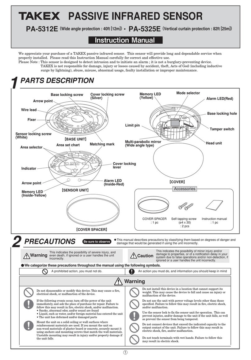
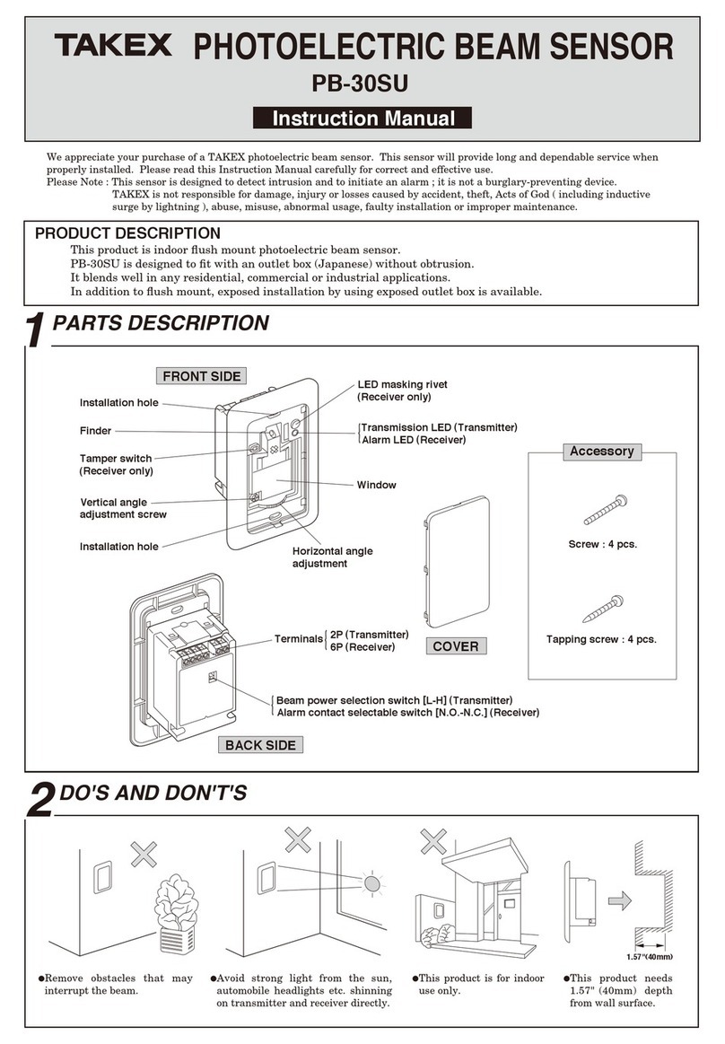
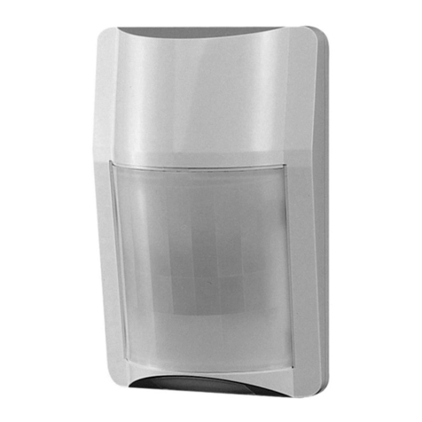
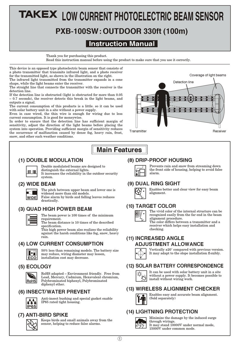
Takex PR-5B User manual

This sensor is only suitable for indoor application.
This sensor consists of a transmitter that emits infrared beam and a
receiver that receives it.
As illustrated below, the infrared beam emitted from the transmitter
is reected in the direction of incidence and then enters the receiver.
A protection loop is formed in the route of the transmitter
reector      receiver.
Whenever this loop is interrupted (if any object should interrupt the
infrared beam), it is detected and an alarm is initiated.
Installation of sensor unit
PHOTOELECTRIC BEAM SENSOR PR-5B
Instruction Manual
Thank you for purchasing the TAKEX product.
This sensor will provide long and dependable service when properly installed.
Please read this Instruction Manual carefully for correct and effective use.
Please note : This sensor is designed to detect intrusion and to initiate an alarm ; it is not a burglary-preventing device.
Sensor
16.5' or less
(5m or less)
Receiver
Transmitter
Alarm is initiated when
the beam is interrupted.
Reflector
0.79" (φ0.2m)
Size of wire used
AWG 22 (Dia. 0.65mm)
AWG 20 (Dia. 0.8mm)
AWG 18 (Dia. 1.0mm)
up to 1000' (300m)
up to 1800' (550m)
up to 2800' (850m)
up to 5000' (1500m)
up to 9000' (2750m)
up to 13500' (4250m)
Input voltage DC 12V DC 24V
To obtain the maximum length of wiring when two or more
sensors are connected, divide the above gures by the
number of units used.
Signal line can be wired up to 3,300ft (1,000m) using AWG
22 telephone wire.
Note 1.
2.
1PRODUCT DESCRIPTION
Mouting hole
Mounting hole
Infrared beam filter
Knockout
Case Terminal cover
(Terminals inside)
Operation LED
Lights when an alarm is initiated.
(A red light is seen through filter.)
Dry contact relay output IC
Contact capacity : 30V AC/DC,
up to 0.5A
POWER
DC10.5〜26V ALARM
COM. N.O.
N.C.
Reflector
1
Reflector mounting
plate
1
Double-faced
adhesive sheet
2
Accessory
●Example 1
●Example 2
1 2 3 4 5 1 2 3 4 5
1 2 3 4 51 2 3 4 5
Power source
for sensor
Power source
for sensor
Signal input
Signal input
(1ch.)
Signal input
(2ch.)
Control panel
Control panel
Sensor
Sensor
LED ON
LED OFF
Tentative
center
Tentative
center
Reflector
Actual center
(installation
position)
When 1 input to plural
sensors are installed.
When plural inputs to plural
sensors are installed.
Unnecessary when additional
sensors are installed.
Fig. 1 Fig. 2
Knockout
Remove terminal cover
(Terminals inside)
①  ②  ③  ④  ⑤
+
−
+
−
}
}
}
}
When a magnetic switch or the like is used in the circuit, insert it in the section .
For more details, refer to instruction manual for control panel.
The dotted lines indicate connections for additional sensors installed.
Remove the terminal cover. Connect the wires with the corresponding terminals correctly as
instructed on the back side of the sensor. Break the knockout if necessary.
Sensor mounting
screw (M3×16)
2
Reflector mounting
screw (M4×16)
2
②Terminal arrangement①Remove
③Wiring distance between sensor and control panel
④Examples of connections
⑤Wiring connections
Note 1.
2.
3WIRING
4
4-1
Installation of reflector
4-2
INSTALLATION
2PARTS DESCRIPTION
Detection activation of this sensor is off-delay (detection time + approx. 1.5 sec.).
For that reason, check protection coverage as the following procedure.
1. Hold the reector against the wall over the "X" mark previously made and check the operation LED on the PR-5B.
2. If the operation LED lights up, check the position where it goes off while moving reector slowly vertically and horizontally by sliding for positioning
tentative center of coverage. * (Fig 1 .) Move the reector as slowly as possible because it takes approx. 1.5 sec at least till operation LED goes off
though the reector comes in coverage. If moving is too fast, the PR-5B will not have time to rest and operation LED will not go off.
3. Check 4 positions (in every directions) where operation LED lights up while moving reector slowly outward from the center.
The center of these 4 positions is an actual
coverage center where reector should be
installed. * (Fig 2.) LED lights up at real time
when reector moves out of coverage (When an
alarm triggers.)
Important : A common mistake is made by holding
the reector in the hand in the air, when
trying to make the PR-5B set up.
This is extremely difcult to achieve.
PLEASE DO NOT ATTEMPT TO DO
THIS.
The following instructions will ensure a successful set up.
1. Select appropriate installation position and determine the best mounting height for application. (PR-5B shall face the direction to be protected.)
2.
Measure the distance from the oor to where the center of the PR-5B main unit will be located. Mark a small "X" on the wall at that point. (Measure and
mark the same distance from the oor on the opposite wall where the reector will be mounted. Ensure that both wallsare reasonably parallel to each other.)
3. Connect the 10.5-26VDC power input and alarm output wires to the appropriate terminal connectors at the rear of the PR-5B.
4. Fix the PR-5B securely to the wall using the "X" mark already made as the center reference on the wall.
Ⅰ
Ⅱ
infrared beam
infrared beam
All manuals and user guides at all-guides.com
all-guides.com
No.05-992 1703
In Japan
Takex America Inc.
4/15 Howleys Road, Notting Hill,
VIC, 3168
Tel : +61 (03) 9544-2477
Fax : +61 (03) 9543-2342
Takenaka Engineering Co., Ltd.
83-1, Gojo-sotokan,
Higashino, Yamashina-ku,
Kyoto 607-8156, Japan
Tel : 81-75-501-6651
Fax : 81-75-593-3816
http : // www. takex-eng. co. jp /
Takex America Inc.
151 San Zeno Way
Sunnyvale,
CA 94086, U.S.A
Tel : 408-747-0100
Fax : 408-734-1100
http : // www. takex. com
Takex Europe Ltd.
Aviary Court, Wade Road,
Basingstoke, Hampshire. RG24 8PE, U.K.
Tel : (+44)01256-475555
Fax : (+44)01256-466268
http : // www. takex. com
In the U.S. In the U.K.
In Australia
Mount the reector as show in Fig 4.Mount the sensor unit as show in Fig 3.
Limited Warranty
Analyze possible problems according to the above table. If normal operation cannot be
restored by the means, contact either the dealer from whom you bought the unit or
TAKEX.
Model
Protected distance
Light source
Response time
Alarm signal
Supply voltage
Power consumption
Ambient temperature range
Mounting positions
Weight
(excluding accessories)
Appearance
PR-5B
16.5' (5m) or less
Infrared light emitting diode
50msec. or more
Dry contact relay output S.P.D.T. form C.
Contact capacity : 30V (AC/DC) up to 0.5A
10.5−26V DC (Non-polarity)
37mA (at 12V DC)
-20°C to +50°C (-4°F to +122°F)
Indoor-entrance, exit, window, passageway
Sensor : 90g (3.2 oz)
Reector : 50g (1.8 oz)
ABS resin (white)
The specications are subject to change without notice.
Fig. 4Fig. 3
Fig. 5
Symptom
No alarm condition
Continuous alarm
Frequent alarm
with no intrusion.
Possible cause Remedy
①Breaker of control panel is
cut off.
(No voltage on power
terminals for sensor)
②Either sensor or reector is
not set in a correct direction.
③Disconnection or separation
of wiring between sensor
and control panel.
Infrared beam lter of the
sensor or the reector is
stained with water drops,
dust, or the like. (Alarm may
be given continuously in
severe cases.)
Moving objects in the protected
area. (like curtain, animal, etc.)
Clean the lter or the
reector with soft cloth.
Remove the moving objects
from the protected area.
Recover the breaker.
(Search the cause of cut-off
of breaker)
Correct the direction of the
sensor or reector with
reference to 4.
Installation of reector.
Repair the disconnection or
separation.
Reflector Reflector
Sensor Sensor
Where the sensor is installed on a
rough or irregular surface like
concrete, use a steel plate of about
2mm in thickness as foundation to
prevent misalignment of the optical
system.
Angle of incidence should be within 15 degrees.
Double-faced adhesive
sheet (Used when sensor
mounting screws are not
used.)
Double-faced adhesive sheet
(
Used when the reflector mounting
screws are not used.
)
Sensor mounting
screws (M3×16)
Reflector mounting
screws (M4×16)
Reflector
mounting plate
Reflector
Operation LED ON
Object which interrupts
the beam.
Reflector mounting
screws (M4×16)
Wall
Sensor
Sensor
Reflector
Reflector
Wall
Wall
Wall
Wall
Wall Wall
Direction of reflector
(φ5mm)
(97mm)
(69mm)
(54mm) (16mm)
φ0.20"
(12.5mm)
TERMINAL COVER
(10mm×8mm)
0.39"×0.31"
WIRING HOLE
KNOCKOUT
(10mm×9mm)
0.39"×0.35"
(23.5mm)
(62mm)
(106mm)
(φ4.4mm)
2-φ0.17"
(φ3.5mm)
2-φ0.14"
3.31"
0.63"
2.13" 3.82"
2.72" 0.49"
0.93"
4.17"
2.44"
(84mm)
MOUNT HOLE
SENSOR
REFLECTOR MOUNT HOLE
Note: Install the reector within the range of 2'
(0.6m) to 15' (5m) from the sensor.
Note that the installation angle as well as
the position of the reector. (Fig. 5)
The reector has the function of
reecting infrared beam in the direction
of incidence within + / -15 degree of the
incidence angle.
When the reector is tilted, be sure to
use it within the above range.
Note:
TAKEX products are warranted to be free from defects in material and workmanship for 12
months from original date of shipment. Our warranty does not cover damage or failure
caused by Acts of God (including inductive surge by lightning), abuse, misuse, abnormal
usage, faulty installation, improper maintenance or any repairs other than those provided
by TAKEX. All implied warranties with respect to TAKEX, including implied warranties for
merchantability and implied warranties for tness, are limited in duration to 12 months
from original date of shipment. During the Warranty Period, TAKEX will repair or replace,
at its sole option, free of charge, any defective parts returned prepaid. Please provide the
model number of the products, original date of shipment and nature of difculty being
experienced. There will be charges rendered for product repairs made after our Warranty
period has expired.
8DIMENSIONS
6TROUBLESHOOTING 7SPECIFICATIONS
5OPERATION
Mounting
4-3
Supply power to the sensor.
If the sensor faces the reector properly, the
operation LED does not light up.
If the LED lights up, refer to "4. INSTALLA-
TION" and re-adjust.
Next, interrupt the path of infrared beam
between the sensor and the reector with
beam shielding objects (human body or the
other objects which interrupts infrared
beam), and conrm that an alarm is given
and the operation LED lights up.
If the alarm stops when this object is
removed (LED off), the system is working
correctly.
Regular maintenance and inspection by
installer and frequent testing by user are
vital to continuous satisfactory operation of
any alarm system.
All manuals and user guides at all-guides.com

Other Takex Security Sensor manuals

Takex PB-100AT-KH User manual

Takex

Takex PB-100AT-KH User manual

Takex PXB-100ATC-KH User manual

Takex

Takex PXB-100ATC-KH User manual

Takex GS-2000E User manual

Takex

Takex GS-2000E User manual

Takex MS-12 Series User manual

Takex

Takex MS-12 Series User manual

Takex FP-5500E User manual

Takex

Takex FP-5500E User manual

Takex SSP-S200 Series User manual

Takex

Takex SSP-S200 Series User manual

Takex PIR-T45WP User manual

Takex

Takex PIR-T45WP User manual

Takex MX-12FAM User manual

Takex

Takex MX-12FAM User manual

Takex MX-12FAMD User manual

Takex

Takex MX-12FAMD User manual

Takex PA-5312E User manual

Takex

Takex PA-5312E User manual

Takex PA-6614E User manual

Takex

Takex PA-6614E User manual

Takex MS-100E User manual

Takex

Takex MS-100E User manual

Takex PB-30SU User manual

Takex

Takex PB-30SU User manual

Takex Quad PB-IN-50HF User manual

Takex

Takex Quad PB-IN-50HF User manual

Takex TXF-125-KH User manual

Takex

Takex TXF-125-KH User manual

Takex PXB-100SW User manual

Takex

Takex PXB-100SW User manual

Takex PIR-T15WE(W) User manual

Takex

Takex PIR-T15WE(W) User manual

Takex PA-6812E User manual

Takex

Takex PA-6812E User manual

Takex Quad PB-IN-50HF User manual

Takex

Takex Quad PB-IN-50HF User manual

Popular Security Sensor manuals by other brands

RKI Instruments 35-3001-01H Operator's manual

RKI Instruments

RKI Instruments 35-3001-01H Operator's manual

Bosch Blue Line D1-P quick start guide

Bosch

Bosch Blue Line D1-P quick start guide

Viking LDB-2 product manual

Viking

Viking LDB-2 product manual

SIUI CTS-9006 Operation manual

SIUI

SIUI CTS-9006 Operation manual

BEA WIZARD II SMR user guide

BEA

BEA WIZARD II SMR user guide

bolid S2000-IK Rev.03 instruction manual

bolid

bolid S2000-IK Rev.03 instruction manual

Agilent Technologies G1314B user manual

Agilent Technologies

Agilent Technologies G1314B user manual

DSC LC-100-PI installation manual

DSC

DSC LC-100-PI installation manual

Visonic NEXT DUO installation instructions

Visonic

Visonic NEXT DUO installation instructions

WITTUR USG-25P operating instructions

WITTUR

WITTUR USG-25P operating instructions

showhome ZW112 manual

showhome

showhome ZW112 manual

Robertshaw 365A instruction manual

Robertshaw

Robertshaw 365A instruction manual

Gewiss GW 10 716 manual

Gewiss

Gewiss GW 10 716 manual

STEINEL PROFESSIONAL IS 345 MX PF manual

STEINEL PROFESSIONAL

STEINEL PROFESSIONAL IS 345 MX PF manual

hager TCC510S User instructions

hager

hager TCC510S User instructions

STEINEL PROFESSIONAL IS 2180-2 Information

STEINEL PROFESSIONAL

STEINEL PROFESSIONAL IS 2180-2 Information

CENS PROFLEX user guide

CENS

CENS PROFLEX user guide

SYR SefeTech Connect Operation and maintenance

SYR

SYR SefeTech Connect Operation and maintenance

manuals.online logo
manuals.online logoBrands
  • About & Mission
  • Contact us
  • Privacy Policy
  • Terms and Conditions

Copyright 2025 Manuals.Online. All Rights Reserved.