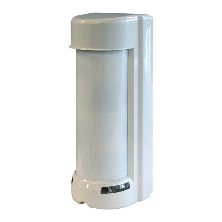
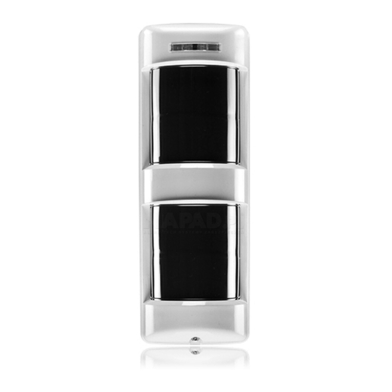
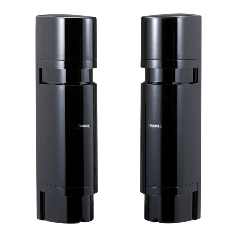
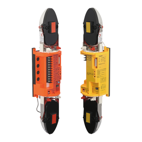
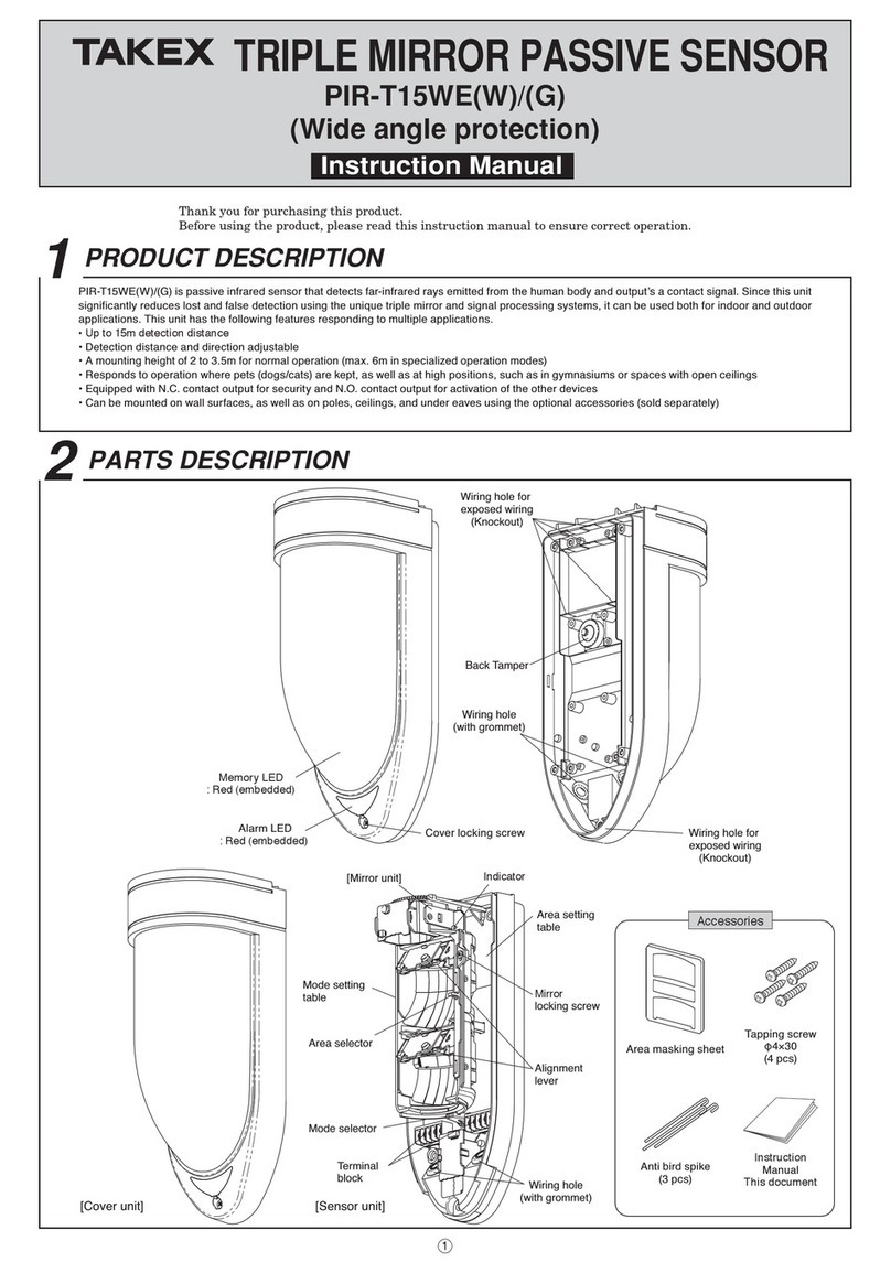
Takex Quad PB-IN-50HF User manual

Thank you for purchasing our "intelligent" quad photoelectric beam. This unit will provide long term dependable service when properly
installed. Please read the Instruction Manual carefully for correct and effective use.
Please note: This sensor is designed to detect intrusion and initiate an alarm; it is not a burglary-preventing device. TAKEX is
not responsible for damage, injury or losses caused by accident, theft, Acts of God (including inductive surge by
lightning), abuse, misuse, abnormal usage, faulty installation of improper maintenance.
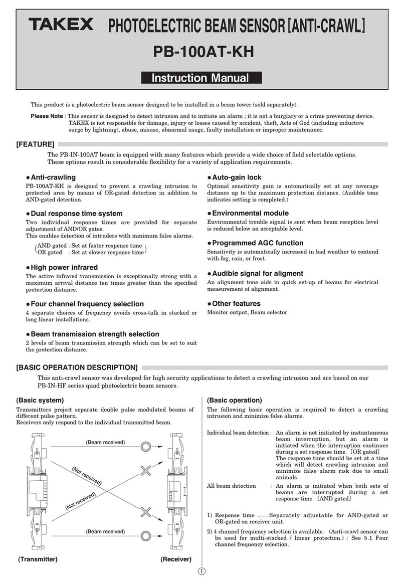
• Four synchronised beams
4 beams are "and-gated" which helps to prevent false alarms
from flying debris and small animals.
• High power infrared
The active infrared transmission is exceptionally strong with a
maximum arrival distance ten times greater than the specified
protection distance.
• Four frequency selections
4 separate choices of frequency avoids cross-talk in stacked or
long linear installations. Allows stacking of Transmitters or
Receivers all on one side.
• Beam transmission strength selection
2 levels of beam transmission strength, which can be set to suit
the protection distance.
• Auto-gain lock
Optimal sensitivity gain is automatically set at any coverage
distance up to the maximum protection distance. (Audible
tone indicates setting is completed.)
PHOTOELECTRIC BEAM SENSOR [INTELLIGENT]
PB-IN-50HF OUTDOOR 165' (50m) INDOOR 330' (100m)
PB-IN-100HF OUTDOOR 330' (100m) INDOOR 660' (200m)
PB-IN-200HF OUTDOOR 660' (200m) INDOOR1320' (400m)
INSTRUCTION
MANUAL
FEATURE
The PB-IN-HF series beams are equipped with many features, which provide a wide choice of field selectable options.
These options result in considerable flexibility for a variety of application requirements. The features are;
• Environmental module
Environmental trouble signal is sent when beam reception level is
reduced below an acceptable level.
• Programmed AGC function
Sensitivity is automatically increased in bad weather to contend
with fog, rain, or frost.
• Alarm memory indicator
Alarm memory LED located on Receiver can be manually reset
(at sensor) or remotely controlled via panel.
• Audible signal for alignment
An alignment tone aids in quick set-up of beams for electrical
measurement of alignment.
• Other features
Monitor output, Response time changeover, Tamper output.
1.
1PARTS DESCRIPTION
Cover Mirror View finder Mounting plate
Bracket
Knockout
Knockout
Pole cover
Horizontal fine
adjustment screw
Vertical
adjustment screw
Gain lock switch
(Receiver only)
Functions indications
as below
[Transmitter] [Receiver]
Operation LED
Beam channel
(frequency 1-4)
(1ch. set at factory)
Mirror
Sensitivity attenuation LED
Beam channel (frequency 1-4)
(1ch. set at factory)
Environmental output terminal
Alarm LED
Response time adjustment
(50msec. set at factory)
Monitor jack
Adjustment dial
Tamper switch
(Receiver only)
Terminals
Functions / Indications
SOLD SEPARATELY
Shading plate
Tapping screw
(ø4x30) : 8
Oval countersunk
head screw
(ø4x20) : 8
Accessory

2.
2
CAUTIONS
Position the sensor with consideration to installation site, installation height and protection distance for effective use.
1) DON'T'S 2) Installation height and protection distance
Avoid strong light from sun,
automobile headlights etc.
shining on transmitter or
receiver (Avoid light in a
direct path of ±2"of optical
axis.)
Do not install in a site where
beam may be interrupted by
trees or plants, consider
seasonal changes.
•
Do not install the unit on
unsteady surfaces.
•
Do not install in places where
units may be splashed
continuously by dirty water or
direct sea spray.
(Causes dirt or salt build-up on
enclosures.)
•
In most cases, the beam should be installed at a height of
27.5" to 35.5" (70cm-90cm).
•
Protection distance
A
95mm
95mm
134mm

6. Wiring Distance between sensor and control panel. Note
•Max. wiring distance
when two or more sets
are connected is the
above value divided by
the number of sets.
•The signal line can be
wired to a distance of
up to approx. 3281’
(1000m) with AGW 22
(Dia. 0.65mm)
telephone wire.
• When using this product in a Mercantile Burglar Alarm, UL681, tamper switch should be connected to a 24-hour supervisory loop.
*Standby battery -Be sure the control panel is equipped with adequate standby battery and charging circuit.
Use 12V (at least) Nicd or lead acid battery with minimum capacity of 0.5AH.
- Estimated battery life - •Unit should be
connected to a listed,
class 2 power source
capable of providing
standby power for a
minimum of 4 hours.
PB-IN-50HF PB-IN-100HF PB-IN-200HF
Wire Size Dia. 12V 24V 12V 24V 12V 24V
AWG22 0.65 394' (120m) 3610' (1100m) 361' (110m) 3281' (1000m) 328' (100m) 2953' ( 900m)
AWG20 0.80 690' (210m) 6234' (1900m) 624' (190m) 5578' (1700m) 525' (160m) 4921' (1500m)
AWG18 1.00 1017' (310m) 9187' (2800m) 920' (280m) 8203' (2500m) 820' (250m) 7218' (2200m)
AWG17 1.10 1246' (380m) 11156' (3400m) 1116' (340m) 9843' (3000m) 985' (300m) 8860' (2700m)
AWG16 1.25 1640' (500m) 14765' (4500m) 1477' (450m) 13452' (4100m) 1312' (400m) 11811' (3600m)
AWG15 1.40 2198' (670m) 19686' (6000m) 2000' (610m) 18046' (5500m) 1739' (530m) 15750' (4800m)
AWG14 1.60 2756' (840m) 24936' (7600m) 2494' (760m) 22311' (6800m) 2166' (660m) 19686' (6000m)
PB-IN-50HF PB-IN-100HF PB-IN-200HF
No. of Md AA Gel Cell Gel Cell Md AA Gel Cell Gel Cell Md AA Gel Cell Gel Cell
pairs 0.5 AH 1.0AH 5.0AH 0.5 AH 1.0AH 5.0AH 0.5 AH 1.0AH 5.0AH
1 8 hr. 16 hr. 83 hr. 7 hr. 14 hr. 71 hr. 5 hr. 11 hr. 58 hr.
2 - 8 hr. 41 hr. - 7 hr. 35 hr. - 5 hr. 29 hr.
4 - - 20 hr. - - 17 hr. - - 14 hr.
8 - - 10 hr. - - 8 hr. - - 7 hr.
3.
The units can be mounted easily on a
pole or flat surface.
Direction by rotary mirror.
Using the adjustment dial and
adjustment screws, the mirrors can
move horizontally (±90 degrees) and
vertically (±10 degrees) allowing the
sensor to work in all directions.
•
1) 2)
±10˚
±90˚
(Ex.1) (Ex.2) (Ex.3)
4
INSTALLATION
Remove cover via
screw at base
of cover.
Loosen screws that fix
the sensor body on the
mounting plate, and
slide the mounting plate
downward to detach it.

4.
Attach four U brackets to poles in two pairs, one on top of the other,
facing opposite directions.
(See illustration.)
•
(3) Pole mounting back to back.
Attach U brackets to pole and secure to mounting plate with
screws.
Attach sensor body.
Pull through wire.
Connect terminals.
Attach covers. (Break knockouts on cover and *pole cover to adapt
to pole diameter and configuration.)
•
•
•
•
•
Grommet
The grommet is compatible with a wire of ø3mm to ø6mm
outer dia.
When a wire of more than ø6mm outer dia. is used, cut off
the dotted line portion on the below figure by pliers or the
like.
Do not fail to plug opening of wire hole to prevent insects
from entering into the unit.
•
ø1.50" (ø38mm) inner
ø1.89" (ø45mm) outer
Grommet
U bracket
Knockout
Knockout
Knockout
*SOLD SEPARATELY

5.
5
SET-UP OF FUNCTIONS AND BEAM ALIGNMENT
6
OPERATION CHECK
1) Supply power with cover detached.
2) Set function options.
(Refer to 7. FUNCTIONS DESCRIPTION for
detailed explanation of each option.)
3) Adjust optical angle.
1) Look through view finder on either side of transmitter optical
unit and move until receiver unit is visible.
2) Repeat the procedure for lower optical unit, and then repeat on
receiver.
4) Fine tuning
Initial beam alignment
can be achieved by
using the alignment
tone indicator.
1) Attach the shading
plates (stored on
sides on both TR/RE)
to the lower optics of
both TR and RE.
2) Turn the receiver
alignment tone switch to ON.
3) Adjust the optics with the adjustment screws until
highest tone is reached. (Note: There will be no sound if
the attenuation alignment tone LED is lit.)
4) Reverse the procedure, i.e. attach shading plates to upper optics
of TR/RE and repeat adjustment.
5) After adjustment, replace the shading plates in storage areas
of TR/RE.
6) Turn the alignment tone indicator to OFF.
3) If there is a continuous "beep" sound, detach receiver cover
and re-adjust referring to section 5 part 3) Auto-gain lock
function.
Confirm a Beep sound with the
bottom end of cover lightly pushed
not to interrupt the beam.
Pre-attach cover.
5) Attach cover.
1) Attach transmitter cover, first.
2) Confirm that receiver
sensitivity attenuation LED
stays OFF. Place cover in
position, but do not secure. A
"beep" sound will occur after
5 seconds. After this signal,
secure the receiver cover with
screws.
[Receiver]
1) Sensitivity allowance is automatically set when the beep
sound is initiated.
2) If tone alignment switch is left accidentally ON, tone will
stop when receiver cover is pre-attached.
Note
Alignment
Poor, Re-adjust
Voltage reading
2.7V or more
2.0 to 2.7V
2.0V or less
Best
Good
1) Alarm LED only.
2) Alarm LED and sound check via tone alignment switch. If tone
alignment switch is set to "ON", tone will stop when cover is
replaced but be effective for an audible test of operation for five
minutes after auto-gain is locked.
After installation, alignment and auto-gain set, test operation by walk testing the beam. Two methods may be used :
RE
Lights
TR
1) Check by alarm LED
RE
Beep
TR
2) Check by walk test mode
Location Functions Function Switches
TR/RE Beam channel
(frequency) 1 ch. 2 ch. 3 ch.
4 ch.
TR. only Beam power HL
'Beep' alignment tone
ON OFF
50msec. (standard)
Response time
adjustment
RE. only
Sensitivity attenuation
LED
(Lights when beam
reception is below
minimal level.)
Alignment tone
switch
Monitor jack
Tighten up screws.
View finder
Adjustment dial
Horizontal fine
Adjustment screw
Vertical
Adjustment screw
Voltmeter
(10V DC)
Beep

6.
7
FUNCTIONS DESCRIPTION
1. Four channel frequency selection
The beam pairs may be set at various frequency levels to
avoid crosstalk between units which are stacked, in-line, or
other configurations which have the potential of spill-over
transmission from one beam to another. Set the frequency
level as illustrated.
1) Linear protection
3) Double stacked linear protection
MAKE SURE TRANSMITTER AND RECEIVER OF
PAIR ARE SET AT SAME CHANNEL ! Paired TR/RE
will not set up unless set at the same channel.
2) Double stack protection
4) Perimeter protection
2. Beam power selection
4. Auto-gain lock function
5) Perimeter double stacked protection
This option allows field selection of the appropriate beam
intensity relative to the application. For distance significantly
less than the specified protection distance, the beam intensity
should be reduced to eliminate potential reflection problems.
For zones reaching maximum protection distance, the beam level
should be set to the highest level.
The use of a voltmeter for alignment is advised to ensure
highest level of stability.
•
Note : For interior applications where greater chance for
reflection occurs, the setting should be at LOW.
1) The auto-gain lock serves to standardise the responsiveness
and tolerance level of the units regardless of varying
distance in an installation.
The situations above have exactly the same tolerance and responsiveness
levels even though the distance are different.
1ch1ch
TR. RE.

7.
5. Tone indicator
2) A "beep" tone is issued from the receiver approximately 5 seconds after the cover is put into position.
This tone indicates the Auto-gain has been set. Refer to the chart below.
Note 1)
2)
3)
A tone is generated regardless of whether "beep" (alignment tone) switch is set to ON or OFF.
The auto-gain setting is locked in for approximately two weeks even if power is disrupted.
If the receiver cover is detached while power is supplied or if power is discontinued for longer than two weeks
(but cover left in place), the auto-gain automatically reset to maximum sensitivity. (Gain is automatically locked
with power re-supplied.)
This feature provides audible testing or signals for the following items.
7. Environmental Module
The environmental signal is initiated if the beam reception level
is reduced to approx 50% or more. The module "Watches" for a
gradual degradation of the beam reception which is indicative of
extremely poor weather conditions. NC or NO signal output is
selectable.
[Contact capacity 30V (AC/DC) 0.5A or less]
Tone Indicates Result Cause Remedy
Optimal sensitivity has
been set.
One pulse
(Beep) OK
Continuous
tone (20
seconds)
Optimal sensitivity can
not be set. NG 1. Beam is interrupted once cover is
replaced.
2. Beams are mis-aligned and sensitivity
attenuation LED lights.
1. Remove any blockage items or ensure
hand is not breaking beam if holding
cover in temporary position.
2. Check beam power setting at transmitter
with cover attached and re-adjust beam
alignment.
Test / Signal Alignment tone switch Other condition Description
Reception strength monitored. Tone pitch increases as reception
improves.
(Note : No tone is given if sensitivity attenuation LED is lit or
if receiver cover is attached.)
•
Beam alignment ON Receiver cover
detached.
For approx. 5 min.
after gain is locked. Tone is linked to alarm LED. Both trip simultaneously.
•
After receiver cover
is attached. Short tone indicates lock is set.
Continuous tone (20sec.) indicates readjustment.
•
ON
ON or OFF
Walk test
Auto-gain lock
6. 137Kpoo

Symptoms Possible cause Remedy
Operation LED 1. Disruption of power or inadequate power 1. Correct power source
does not light 2. Bad wiring connection or broken wire, short 2. Check and correct wiring
Receiver Alarm 1. Disruption of power or inadequate power 1. Correct power source
LED does not 2. Bad wiring connection or broken wire, short 2. Check and correct wiring
light when the 3. Reflection of beam is flooding receiver and 3. Remove reflecting object. Set beam power to
beam is broken sent into the receiver Low. Contact TAKEX for further remedies
4. Four beams are not broken simultaneously 4. Ensure all beams are broken at same time
5. Beam interruption time is shorter than response time 5. Adjust response time
Receiver Alarm 1. Alignment is off 1. Check and adjust
LED stays on 2. Shading object between transmitter and receiver 2. Check site/remove any possible obstacles
3. Optics of units are soiled 3. Clean the optics with a soft cloth
4. Frequency channel setting on transmitter 4. Readjust to be the same channel
does not match with that on receiver
Intermittent alarm 1. Bad wiring connection 1. Check again
2. Change of supply voltage 2. Stabilise supply voltage
3. Shading object between transmitter and receiver 3. Remove the shading object
4. The wiring of power machine is located nearby 4. Change the place for installation
transmitter and receiver
5. Stabilise 5. Unstable installation of transmitter and receiver
6. Optics of units are soiled 6. Clean the optics with soft cloth
7. Improper alignment 7. Check and re-adjust
8. Small animals may pass through the 4 beams 8. Change environments or the place for installation
9. Beam power switch is set at L, which does not 9. Set beam power switch at H and make the unit
keep enough sensitivity allowance gain-locked with receiver cover detached
Model PB-IN-50HF PB-IN-100HF PB-IN-200HF
Detection System Near infrared beam interruption system
(TR. - RE. 4 beams simultaneous interruption)
Infrared beam Double modulation pulsed beam by LED
Protection Outdoor 165’ Outdoor 330’ Outdoor 660’
distance (50m) or less (100m) or less (200m) or less
Max. arrival Tenfold Tenfold ) Tenfold
distance 1640’ (500m) 3280’ (1000m) 6560’(2000m)
Response time 50msec. to 700msec variable (Standard: 50msec.)
Power Supply 12V to 30V DC (non-polarity)
Current 60mA or less 70mA or less 85mA or less
consumption at protection at protection at protection
(Max. 95mA (Max. 105mA (Max. 120mA
or less) or less) or less)
Alarm Output Dry contact relay output 1c
Reset: interruption time + off-delay (Approx. 1.5 sec.)
Contact capacity: 30V AC/DC, 1A or less
Environmental Dry contact relay: 1a or 1b (switchover)
output Contact operation: Output when weather condition gets worse
Contact capacity: 30V AC/DC,1A or less
Tamper output Dry contact relay: 1b
Contact operation: Output when receiver cover is detached
Contact capacity: 30V AC/DC, 0.1 A or less
Alarm LED Red LED (receiver) lights when an alarm is initiated
Sensitivity Red LED (receiver) lights when beam reception is attenuated
attenuation LED
Functions Modulated beam frequency selection, Tone indicator,
Environmental module, Beam power selection,
Alarm memory indication, Programmed AGC. Auto-gain lock
function. Monitor jack.
Beam adjustment Horizontal: ±90˚, Vertical: ±10˚
Ambient temperature -31˚F to + 151˚F (-35˚C to +66˚C)
Mounting position Outdoor, Indoor
Wiring Terminals
Weight Transmitter: 42 oz (1200g) Receiver : 45.5 oz (1300g)
Appearance PC resin (wine red)
8.
(Units should be tested on a regular weekly basis)
Other manuals for Quad PB-IN-50HF
1
This manual suits for next models
2
Table of contents
Other Takex Security Sensor manuals

Takex
Takex PIR-T15WE(W) User manual

Takex
Takex Quad PB-IN-50HF User manual

Takex
Takex PXB-100ATC-KH User manual

Takex
Takex PIR-T45WP User manual

Takex
Takex PA-6812E User manual

Takex
Takex PB-30SU User manual

Takex
Takex PXB-100SW User manual

Takex
Takex MS-12 Series User manual

Takex
Takex MX-12FAM User manual

Takex
Takex PA-5312E User manual