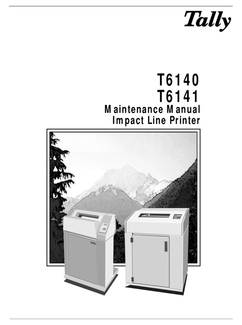
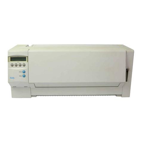
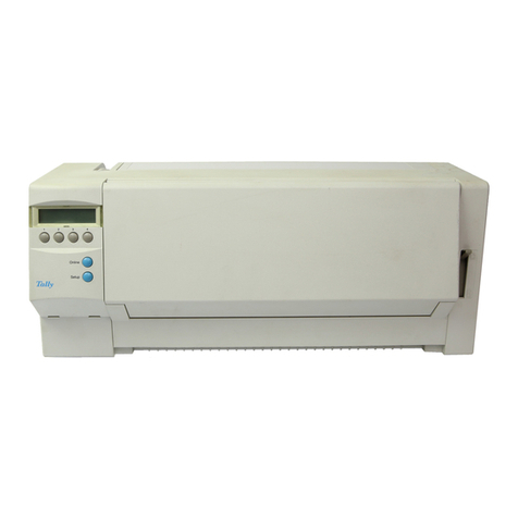
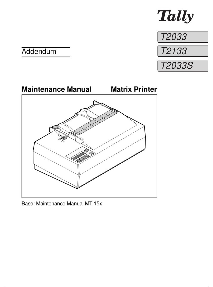
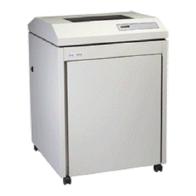
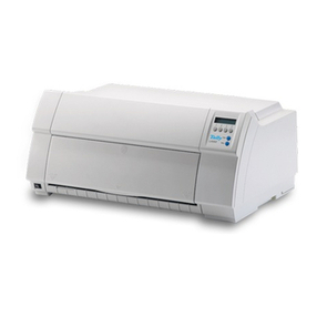
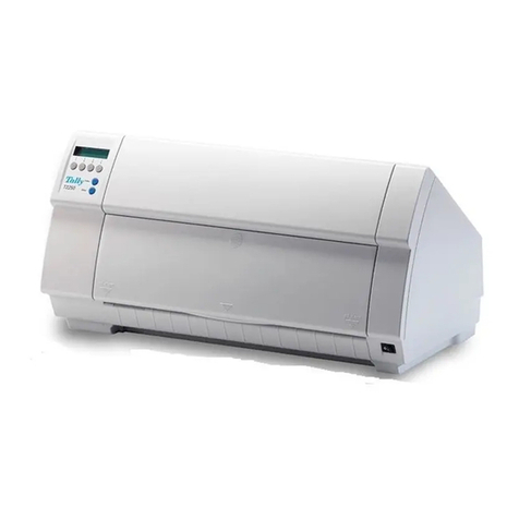
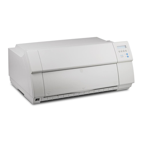
Tally T2040 User manual

Maintenance Manual Matrix Printer
T2040
T2140


Table of contents
1 Introduction . . . . . . . . . . . . . . . . . . . . . . . . . . 1-1
2 Specifications . . . . . . . . . . . . . . . . . . . . . . . . . 2-1
2.1 Printer specifications . . . . . . . . . . . . . . . . . . . . . . . . 2-1
2.2 Interface specifications . . . . . . . . . . . . . . . . . . . . . . . 2-4
2.3 Paper specifications . . . . . . . . . . . . . . . . . . . . . . . . . 2-5
3 Functional description . . . . . . . . . . . . . . . . . . . . . 3-1
3.1 Electronic functions . . . . . . . . . . . . . . . . . . . . . . . . . 3-1
3.2 Mechanical functions FAW . . . . . . . . . . . . . . . . . . . . . 3-2
3.2.1 Function . . . . . . . . . . . . . . . . . . . . . . . . . . . . . . . . 3-2
3.2.2 Pushbar position check . . . . . . . . . . . . . . . . . . . . . . . . 3-2
3.2.3 Pushbar positions . . . . . . . . . . . . . . . . . . . . . . . . . . . 3-2
3.2.4 Single-sheet mode . . . . . . . . . . . . . . . . . . . . . . . . . . 3-5
3.2.5 Changeover to tractor mode . . . . . . . . . . . . . . . . . . . . . 3-5
3.2.6 Changeover to AGA mode . . . . . . . . . . . . . . . . . . . . . . 3-5
4 Test functions, troubleshooting and maintenance . . . . . 4-1
4.1 Key functions when turning on the printer . . . . . . . . . . . . 4-1
4.2 Testmode . . . . . . . . . . . . . . . . . . . . . . . . . . . . . . . 4-2
4.2.1 Rolling ASCII . . . . . . . . . . . . . . . . . . . . . . . . . . . . . 4-3
4.2.2 Interface test (Hex-Dump) . . . . . . . . . . . . . . . . . . . . . . 4-4
4.2.3 Setting the Formlen function . . . . . . . . . . . . . . . . . . . . . 4-5
4.2.4 Setting the AGA function . . . . . . . . . . . . . . . . . . . . . . . 4-5
4.2.5 Setting the Paphand function . . . . . . . . . . . . . . . . . . . . . 4-6
4.2.6 CX-bid . . . . . . . . . . . . . . . . . . . . . . . . . . . . . . . . . 4-8
4.2.7 Wrap . . . . . . . . . . . . . . . . . . . . . . . . . . . . . . . . . 4-8
4.2.8 Sound . . . . . . . . . . . . . . . . . . . . . . . . . . . . . . . . . 4-8
4.3 Showon function . . . . . . . . . . . . . . . . . . . . . . . . . . . 4-9
4.4 AGA test . . . . . . . . . . . . . . . . . . . . . . . . . . . . . . . 4-9
4.5 Parallelity . . . . . . . . . . . . . . . . . . . . . . . . . . . . . . . 4-11
4.6 Troubleshooting . . . . . . . . . . . . . . . . . . . . . . . . . . . 4-12
4.6.1 Problems with the print quality . . . . . . . . . . . . . . . . . . . . 4-14
4.6.2 Error messages via the display . . . . . . . . . . . . . . . . . . . . 4-15
4.6.3 Additional display messages . . . . . . . . . . . . . . . . . . . . . 4-16
4.7 Maintenance . . . . . . . . . . . . . . . . . . . . . . . . . . . . . 4-17
4.7.1 Replacing the fuse . . . . . . . . . . . . . . . . . . . . . . . . . . 4-17
4.7.2 Cleaning the housing . . . . . . . . . . . . . . . . . . . . . . . . . 4-17
4.7.3 Cleaning the interior . . . . . . . . . . . . . . . . . . . . . . . . . . 4-18
4.7.4 Platen . . . . . . . . . . . . . . . . . . . . . . . . . . . . . . . . . 4-18
4.7.5 Ribbon . . . . . . . . . . . . . . . . . . . . . . . . . . . . . . . . 4-19
4.7.6 Upper friction . . . . . . . . . . . . . . . . . . . . . . . . . . . . . 4-19
4.7.7 Carriage shafts . . . . . . . . . . . . . . . . . . . . . . . . . . . . 4-19
Table of contents

5 Instructions for disassembly and assembly . . . . . . . . . 5-1
5.1 Replacing the casing parts . . . . . . . . . . . . . . . . . . . . . . 5-2
5.1.1 Replacing the upper part of casing . . . . . . . . . . . . . . . . . . . 5-2
5.1.2 Replacing the lower part of casing . . . . . . . . . . . . . . . . . . . 5-6
5.2 Replacing the print head . . . . . . . . . . . . . . . . . . . . . . . 5-8
5.3 Replacing the flap . . . . . . . . . . . . . . . . . . . . . . . . . . 5-10
5.4 Replacing the electronic components . . . . . . . . . . . . . . . 5-11
5.4.1 Replacing the main controller board (incl. casing) . . . . . . . . . . 5-11
5.4.2 Replacing the power supply . . . . . . . . . . . . . . . . . . . . . 5-12
5.4.3 Replacing the panel board . . . . . . . . . . . . . . . . . . . . . . 5-14
5.5 Replacing the FAW motor . . . . . . . . . . . . . . . . . . . . . 5-15
5.6 Replacing the paper transport motor . . . . . . . . . . . . . . . 5-16
5.7 Replacing incremental strip . . . . . . . . . . . . . . . . . . . . 5-17
5.8 Replacing the AGA sensor . . . . . . . . . . . . . . . . . . . . 5-18
5.9 Replacing timing station sensor . . . . . . . . . . . . . . . . . . 5-19
5.10 Replacing the home position sensor . . . . . . . . . . . . . . . 5-20
5.11 Replacing the printhead cable . . . . . . . . . . . . . . . . . . . 5-21
5.12 Replacing the ribbon drive . . . . . . . . . . . . . . . . . . . . . 5-22
5.13 Replacing the carriage . . . . . . . . . . . . . . . . . . . . . . . 5-23
5.14 Replacing the carriage motor . . . . . . . . . . . . . . . . . . . 5-25
5.15 Replacing the printing bar . . . . . . . . . . . . . . . . . . . . . 5-26
5.16 Replacing the PE sensor . . . . . . . . . . . . . . . . . . . . . . 5-27
5.17 Replacing the Friction Drive . . . . . . . . . . . . . . . . . . . . 5-28
5.17.1 Replacing the friction drive shaft front . . . . . . . . . . . . . . . . 5-28
5.17.2 Replacing the lower friction . . . . . . . . . . . . . . . . . . . . . . 5-29
5.18 Replacing the tractor . . . . . . . . . . . . . . . . . . . . . . . . 5-30
5.19 Replacing the switch paper guide . . . . . . . . . . . . . . . . . 5-32
5.20 Replacing the paper transport . . . . . . . . . . . . . . . . . . . 5-33
5.20.1 Replacing the paper guide . . . . . . . . . . . . . . . . . . . . . . 5-33
5.20.2 Replacing driving shaft . . . . . . . . . . . . . . . . . . . . . . . 5-34
5.21 Replacing the side walls . . . . . . . . . . . . . . . . . . . . . . 5-35
5.21.1 Replacing the left side wall (with FAW) . . . . . . . . . . . . . . . 5-35
5.21.2 Replacing the right side wall . . . . . . . . . . . . . . . . . . . . . 5-36
Table of contents
6 Spare parts and schematics . . . . . . . . . . . . . . . . . 6-1
6.1 Housing/Panel . . . . . . . . . . . . . . . . . . . . . . . . . . . . 6-2
6.2 General Arrangement – sheet 1 . . . . . . . . . . . . . . . . . . . 6-4
6.3 General arrangement – sheet 2 . . . . . . . . . . . . . . . . . . . 6-6
6.4 Power supply . . . . . . . . . . . . . . . . . . . . . . . . . . . . 6-8
6.5 Controller . . . . . . . . . . . . . . . . . . . . . . . . . . . . . . . 6-11
6.6 Panel board . . . . . . . . . . . . . . . . . . . . . . . . . . . . . 6-21
6.7 Head connection . . . . . . . . . . . . . . . . . . . . . . . . . . . 6-24
6.8 Recommended spare parts . . . . . . . . . . . . . . . . . . . . . 6-27
Table of contents

1 Introduction
This Matrix Printer has been developed for daily correspondence purposes in the
office. It meets the highest possible technical standards, and with proper use, it
should provide many years of trouble-free operation.
High-performance print qualities as well as operation with fanfold paper and cut
sheets can be chosen.
The following print qualities are available:
Copy Draft Print Qualitiy (DPQ Copy)
Draft Print Quality (DPQ)
Near Letter Quality (NLQ)
Letter Quality (LQ)
The electronic part controlled by a microcomputer operates the needle print head,
menu programming, and interface.
All elements of the printer control are arranged on printed circuit boards so that only
a few additional components are required such as
step motor for selection of paperpath or for automatic gap adjustment
DC-motor for carriage transport
step motor for paper feed
The following features and options will further enhance the printer’s capabilities:
pull tractor 1 (front) (standard)
manual single sheet feeder (front) (standard)
automatic sheet feeder rear (SFR) (option)
automatic sheet feeder front (SFF) (option)
pull tractor 2 (front) (option)
pull tractor 3 (rear) (option)
We recommend the use of original accessores for our printers. The use of others
than original parts may reduce the performance of the printer and cause defects on
the printer. For errors caused by the use of others than original accessories, your
warranty become invalid.
Caution: Activities described herein must only be performed by specially trained
and qualified service personnel! Harmful voltages can be touched.
STOP
Introduction
1-1


2 Specifications
2.1
Printer specifications
Printer system Serial impact matrix printer
Printhead with 24 needles ∅0.25 mm
bidirectional printing
Print speed and
character matrices
DPQ
(Data Print Quality) 400 cps / 10,0 cpi 12 x 12
480 cps / 12,0 cpi 12 x 10
600 cps / 15,0 cpi 08 x 08*
600 cps / 15,0 cpi 12 x 08
510 cps / 17,1 cpi 12 x 12
600 cps / 20,0 cpi 12 x 10
NLQ
(Near Letter Quality) 160 cps / 10,0 cpi 24 x 18
190 cps / 12,0 cpi 24 x 15
250 cps / 15,0 cpi 16 x 16*
250 cps / 15,0 cpi 24 x 16
135 cps / 17,1 cpi 24 x 18
160 cps / 20,0 cpi 24 x 15
LQ
(Letter Quality) 70 cps / 10,0 cpi 24 x 36
90 cps / 12,0 cpi 24 x 30
250 cps / 15,0 cpi 16 x 16*
250 cps / 15,0 cpi 24 x 16
135 cps / 17,1 cpi 24 x 18
160 cps / 20,0 cpi 24 x 15
* Epson emulation only: superscript, subscript,
microscript and MTPL microscipt
Tab speed 3.5 inch/sec.
Print width
Narrow printer
80 characters at 10 cpi
Wide printer
136 characters at 10 cpi
Character pitch 5 / 6 / 7,5 / 8,6 / 10 / 12 / 15 / 17,1 / 20 cpi
Character size
Height 3,32 mm (incl. descenders)
Width 2,19 mm, max. 2,43 mm
Fonts
Standard DPQ, Copy Draft; Courier, Roman, Sanserif,
OCR A + B (all resident in NLQ und LQ);
DLL is standard, but not battery-buffered
Specifications Printer specifications
2-1

Barcodes (standard) A 2/5 Matrix (default)
B 2/5 Industrial
C 2/5 Interleaved
D Code 11
E BCD Matrix
F Code 39
G Codabar
H EAN 8 (with HRI*)
I EAN 8 (without HRI)
J EAN 13 (with HRI)
K EAN 13 (without HRI)
L MSI/modified PLESSEY
M UPC A (with HRI)
N UPC A (without HRI)
O UPC E (with HRI)
P UPC E (without HRI)
Q Delta Distance (IBM)
R Code 128
S EAN 128
Large Character Printing (LCP)
US-Postnet Barcode
* HRI = human readable index
Emulations
Standard – MTPL (Tally Printer Language)
– Epson LQ-2550
– IBM Proprinter XL24e / IBM XL24 + AGM
Optional on request
Resolution 60 to 360 dpi horizontal
90 to 360 dpi vertical
Print attributes in all
character pitches Double width, italics, right justification,
shadowed, auto centered, double height, bold,
proportionally spaced, underlined, overlined,
superscript, subscript
Self-test – ASCII test
– Hex-dump
– Fault display
– Ribbon test
Printer buffer 64 KB
Panel LCD display, 2 x 16 digits
6 function keys:
– Online
– Setup
– 4 softkeys
Noise LWAd = 67 dB(A)
Draft: LPA = 52 dB(A)
NLQ Sanserif: LPA = 52 dB(A)
Continuous operation
Throughput (ECMA 132)
MTBF
>24 000 pages/month DPQ
>400 pages/hour
>10 000 h; 25% DC
Mains voltage 120 V ±10%; 220–240 V -10%, +15%; 50/60 Hz
Printer specifications Specifications
2-2

Power consumption <40 VA
Approvals UL listed, ULc Certification, CE-Certification,
FCC Class B Certification, VDE-GS Certification
Dimensions
Narrow printer Wide printer
Width
Height
Depth
424 mm 600 mm
300 mm 300 mm
399 mm 399 mm
Weight
Narrow printer Wide printer
10.5 kg 13.2 kg
Paper feed
Feed speed 3.5"/sec
Feed first line (6 lpi) 60 ms
View position 3.5"/sec
Reverse motion Up to max. form length (22 inch)
max. 1 inch for automatic single sheet feeder
Printhead gap
Standard Automatic gap adjustment
Paper transport
Standard – Tractor with parking position
– Single sheet via front insertion (friction rollers)
Optional – Automatic single sheet feeder front and rear
(capacity: 80 sheets per feeder)
– Tractor 2 (front) and 3 (rear)
Service life
Printhead 250 millions /DPQ 12 x 12 Matrix
Ribbon
Narrow printer :
3.5 millions characters
Wide printer :
5.0 millions characters
Environmental conditions
Operation
Temperature +10° to +35°C
Rel. humidity 16 to 73%
Climate IEC 721-3-7, Class 7K1
Storage
Temperature -5° to +45°C
Rel. humidity 5 to 95%
Climate IEC 721-3-1, Class 1K3
Transport
Temperature -40° to +70°C
Rel. humidity 5 to 95%
Climate IEC 721-3-2, Class 2K4
Specifications Printer specifications
2-3

2.2
Interface specifications
Parallel interface bidirectional
Type of data
transmission 8-bit parallel interface (Centronics compatible)
IEEE-1284; Nibble mode
Transmission rate Max. 30 KHz
Signal status Low: 0.0 V to +0.4 V
High: +2.4 V to +5.0 V
Connection cable Material AWG no. 28 at least
Length up to 2.5 m
Twisted-pair cable with double-shield,
acc. IEEE Std 1284 – 1294
Interface connections Printer side: Amphenol 57-40360 (or compatible)
Cable side: Amphenol 57-30360 (or compatible)
Serial interface
Type RS232C interface
Synchronization Asynchronous
Transmission rate 600 bauds to 19,200 bauds
Signal status OFF (log. 1) -3 V to -15 V
ON (log. 0) +3 V to +15 V
Connection cable Length up to 15 m
Interface connections ITT Cannon connector
Series DB-9 S
Transmission protocol XON/XOFF, ENQ/STX, READY/BUSY,
Robust XON/XOFF, ACK/NAK, ETX/ACK
Capacity of data buffer 64 KB max.
Interface specifications Specifications
2-4

2.3
Paper specifications
Tractor 1 Continuous paper,
single part forms
Weight 60 to 120 g/m2
Width 76 to 254 mm
(narrow printer)
76 to 420 mm
(wide printer)
Form length 76 to 559 mm
Multi part forms
(to be tested
individually!)
Copies 1 + 5
Weight of original 45 to 65 g/m2
Weight of copies 45 to 56 g/m2
Weight of bottom sheet 45 to 65 g/m2
Thickness (max.) 0.6 mm
Width 76 to 254 mm
(narrow printer)
76 to 420 mm
(wide printer)
Form length 76 to 451 mm
Manual single
sheet feeder Single part forms
Weight 80 to 120 g/m2
Width 76 to 254 mm
(narrow printer)
76 to 420 mm
(wide printer)
Form length 76 to 305 mm
Multi part forms
(to be tested
individually!!)
Copies 1 + 5
Weight of original 50 to 60 g/m2
Weight of copies 45 to 56 g/m2
Weight of bottom sheet 50 to 60 g/m2
Thickness (max.) 0.6 mm
Width 76 to 420 mm
(narrow printer)
76 to 420 mm
(wide printer)
Form length 76 to 305 mm
Envelopes
Width 76 to 420 mm
Length 76 to 305 mm
Thickness 0.32 mm
Specifications Paper specifications
2-5

Printing paper Recycling paper made of 100% waste paper (to DIN 19 309)
can be processed.
Set of forms Sets of forms may be used only if the top edge is bound. The
binding edge should be as soft as possible. A wavy binding
edge may hamper the smooth feeding of these sets. Multi-part
forms have to be inserted with the glued top facing down.
Multi-part forms should be tested for suitability.
Paper quality Light pulp paper of medium fine quality, paper bearing the
quality mark SM Post and photocopy paper are suitable for
use. Unsuitable are: satin-finisch or coated papers, imitation
art papers, and embossed papers.
Since paper as natural material reacts strongly to
environmental influences (e.g. humidity, temperature), the
place of storage should be selected carefully. We recommend
that this kind of paper should be tested extensively before
larger quantities are acquired.
Coloured
paper Should papers with a dark reverse side be used, these should
also be tested for their functionality. Please pay attention to the
use of infrared reflecting colors, when acquiring these papers.
Paper specifications Specifications
2-6

3 Functional description
3.1
Electronic functions The control electronic consists of 8 different assemblies. These are:
Power supply
Control board including parallel and serial interface
Print head
Head connection
Panel board with LC display
Paper feed motor
Carriage motor
Motor FAW (AGA/paper tray selection)
CR
PE + TOF
SENSOR HP
SENSOR
AGA Timing
station
LF FAW
PRINT
HEAD
CONTROL BOARD
PANEL
POWER SUPPLY
Functional description Electronic functions
3-1

3.2
Mechanical functions
FAW
3.2.1
Function The motor FAW controls the pushbar which is used to select the functions. After
switch-on, the carriage moves to the left-hand side of the printer and presses
against the seesaw lever, thus pushing the seesaw outwards. This causes the see-
saw to tilt, and the FAW motor proceeds to control paper tray selection.
The pushbar can execute 6 steps, each 5.5 mm apart. It engages with either the
gear shaft front, the gear shaft rear or the friction front and rear. The gear shafts
control the position of the gears which are used to drive tractors 1, 2 and 3, sheet
feeder rear (SFR) and sheet feeder front (SFF) respectively.
3.2.2
Pushbar position check The home position sensor checks the position of the pushbar and, therefore, the se-
lected paper source. There is a position ruler located on the pushbar. After switch-
on, the photoelectric barrier in the home position sensor scans this ruler; it moves to
the next ridge edge and measures the width of the ridge. The position of the push-
bar is fed back to the firmware in this way.
Ridge 1 (narrow) Tractor 2
Ridge 2 Tractor 3
Ridge 3 Tractor 1
Ridge 4 (wide) Friction switched on (friction front
and rear)
3.2.3
Pushbar positions Possible pushbar positions:
The numbers in brackets in the following description of the pushbar positions are
items which can be found in chapter 6
Spare parts and schematics
.
612
3
4
5
Trac2
Trac3
Trac1
Friction
SFF Friction
SFR +
Single
1234
Ridge
Mechanical functions FAW Functional description
3-2

Pushbar in forward-most
position (position 1) The gear shaft front has lifted the gear (82) from the left-hand side wall (away from
the wall). Tractor 2 is driven as a result.
Pushbar in position 2 If the pushbar moves a further 5.5 mm, the flat gear (76) on the rear of the side wall
is moved inwards (against the wall) and thus engages with the bottom gear (93).
Tractor 3 is now driven by the gear (77).
FAW motor
LF motor
Position 1
Tractor 2
Gear (82) Pushbar
FAW motor
LF motor
Position 2
Tractor 3
Gear (93)
Gear (76)
Gear (77)
Pushbar
Functional description Mechanical functions FAW
3-3

Pushbar in position 31⁄2The next step is 8.25 mm rather than 5.5 mm (i.e. in the middle of the 3rd and 4th
markings). The gear (82) is close to the wall and engages with the gear (79) behind
the white gear (78) which drives tractor 1.
Pushbar in backward-
most position (position 6) The pusher on the pushbar moves arm on the friction axle backwards as far as it
will go, thus switching the friction on. The front and rear friction are actuated, and
both axles are moved from 45 degrees front to 45 degrees rear position.
FAW motor
LF motor
Position 31⁄2
Tractor 1
Gear (82)
Gear (79) behind
Gear (78)
Pushbar
FAW motor
LF motor
Position 6
Friction rear
Friction
front
Pusher
Pusher
Pushbar
Mechanical functions FAW Functional description
3-4

3.2.4
Single-sheet mode
SFR The pushbar moves to position 6, at which point the tractors are idle, and the friction
is switched on. The pushbar then moves to position 5. The gear (76) moves to posi-
tion 2 (away from the side wall), thus rendering inactive the gear (77) used to drive
tractor 3. The only operative gear (74) is the one used to drive the SFR. The LF
motor moves back and forth to synchronise the SFR clutch in load position.
SFF The pushbar moves to position 6, and the gear (82) is lifted (position 2) and swit-
ches to friction. Paper is transported to the PE sensor position by reverse steps of
the LF motor. Then the sense of rotation is inversed. Paper transport is effected by
friction, the SFF is in the free-wheel position. The paper transport in the SFF is only
activated for printer reverse motion. If much paper is to be fed back, pushbar posi-
tion 5 is used.
Manual sheet feeder The pushbar moves to position 6, and the gear (82) is lifted (position 2) and swit-
ches to friction. The manual sheet feeder transports paper to the PE sensor. The
pushbar then returns to position 5, the gear (82) moves centre between the position
against and away from the wall and the paper is pulled in by means of the friction.
3.2.5
Changeover to tractor
mode If tractor mode is to be re-engaged, the pushbar moves to its initial position (1) and
both frictions are switched off. Tractor selection can then commence.
3.2.6
Changeover to AGA
mode As soon as the carriage moves to the right, the motor FAW starts the AGA. The
gear (72) in the seesaw is fixed in position when the FAW motor is switched to
AGA.
Functional description Mechanical functions FAW
3-5

Other manuals for T2040
2
This manual suits for next models
1
Table of contents
Other Tally Printer manuals

Tally
Tally T9020 User manual

Tally
Tally T2024/24 User manual

Tally
Tally T9312 User manual

Tally
Tally T2240/24 User manual

Tally
Tally T6218 Configuration guide

Tally
Tally T2280 SprintPro User manual

Tally
Tally Xpress T8016 User manual

Tally
Tally T3016 User manual

Tally
Tally Dascom 1125 User manual

Tally
Tally T2265 SprintPro User manual