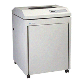
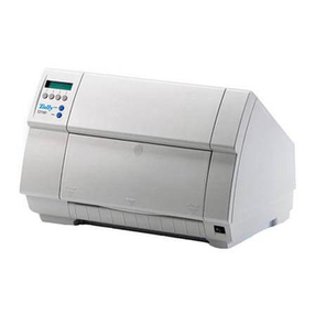
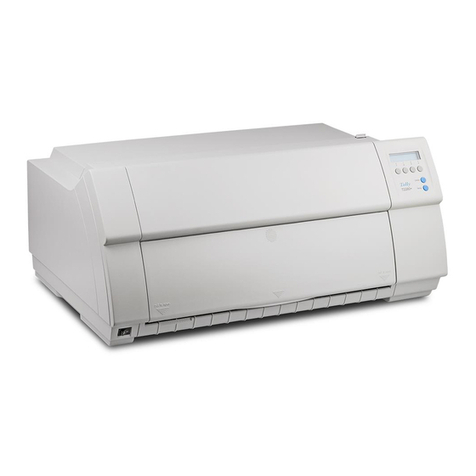
Tally T6218 Configuration guide

T6218 Maintenance Manual Supplement
Supplement to the T6215 Maintenance Manual
1149-084775

T6218 Maintenance Manual Supplement
2 Tally Printer Corp. P/N 1149-084775
PROPRIETARY NOTICE
This document and the information contained therein are the property of
TALLY. Recipient agrees not to: (1) use such information for purposes
other than those expressly authorized by TALLY; or (2) furnish such
information to any other person in whole or in part for any purpose
whatsoever, without the express authorization of TALLY. Recipient also
agrees not to reproduce or copy this document either whole or in part
without the prior express written permission of TALLY upon receipt of a
request therefore.

Table of Contents
P/N 1149-084775 Tally Printer Corp. 3
Table of Contents
Introduction _________________________________________________________________ 5
Supplement to Chapter 1: Technical Overview______________________________________ 7
New Features ______________________________________________________________ 7
On-the-Fly Coil Temperature Measurement for the T6218 _________________________ 7
Automatic Paper Motion Fault Retry __________________________________________ 7
Performance_______________________________________________________________ 8
Print Speeds______________________________________________________________ 8
Plot Speeds ______________________________________________________________ 8
Paper Advance____________________________________________________________ 9
Specifications _____________________________________________________________ 10
Weight _________________________________________________________________ 10
Dimensions _____________________________________________________________ 10
Environment ____________________________________________________________ 10
Acoustics _______________________________________________________________ 11
Site, Power, and Space Requirements_________________________________________ 11
Space Requirements ______________________________________________________ 11
Service Life _____________________________________________________________ 11
Heat Load Contribution____________________________________________________ 12
Reliability ______________________________________________________________ 12
Safety Features __________________________________________________________ 12
Maintainability __________________________________________________________ 13
Agency Approvals________________________________________________________ 13
Supplement to Chapter 2: Menu Operations ______________________________________ 15
New Shuttle Stroke Calibration ______________________________________________ 15
Enhanced Print Quality Control Panel Option _________________________________ 16
Twinax Graphics AVM Control Panel Option__________________________________ 17
Legacy Overprint Control Panel Options______________________________________ 18
Supplement to Chapter 3: Faults and Troubleshooting ______________________________ 19
Supplement to Chapter 4: Removing and Replacing Components _____________________ 21
Procedure 5: Hammer Bank Removal ______________________________________ 21
Procedure 13: Distribution PCA Removal ___________________________________ 24
Procedure 13A: Surge Capacitor Replacement________________________________ 25
Procedure 20: Power Supply Removal_______________________________________ 25
Procedure 21: Platen Sensor PCA Removal __________________________________ 26
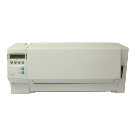
T6218 Maintenance Manual Supplement
4 Tally Printer Corp. P/N 1149-084775
Table of Figures
Figure 1. T6218 Cable Assembly Diagram_________________________________________ 20
Figure 2. Hex KEPS Nuts Locations______________________________________________ 21
Figure 3. Wedge Location______________________________________________________ 22
Figure 4. Adjusting Wedge Pressure______________________________________________ 22
Figure 5. Hammer Bank Cable Clamp Locations____________________________________ 24
Figure 6. Distribution PCA Screws_______________________________________________ 24
Figure 7. Surge Capacitor and Screw Location _____________________________________ 25
Figure 8. Power Supply Assembly________________________________________________ 25
Figure 9. Platen Sensor PCA Location____________________________________________ 26
Figure 10. Platen Sensor PCA __________________________________________________ 26
Introduction
P/N 1149-084775 Tally Printer Corp. 5
Introduction
This manual is a supplement to the T6215 Maintenance Manual, Tally part number 083644. The
purpose of this manual is to support the T6218 model, a new entry in the T6215 family of
printers. Any differences between the T6215 and the T6218 are documented herein.
There are chapters in this manual that address the differences in the respective chapter of the
T6215 Maintenance Manual. These chapters are:
Supplement to Chapter 1: Technical Overview
Supplement to Chapter 2: Menu Operations
Supplement to Chapter 3: Faults and Troubleshooting
Supplement to Chapter 4: Removing and Replacing Components
At the end of this manual are a number of engineering drawings. When printing this manual, the
best results are obtained by printing the text sections on Letter (8 ½” x 11”) size paper and the
drawings on Tabloid (11” x 17”) size paper. The drawings are also best viewed when printed on
printers with 600 DPI resolution or better.

T6218 Maintenance Manual Supplement
6 Tally Printer Corp. P/N 1149-084775

Technical Overview
P/N 1149-084775 Tally Printer Corp. 7
Supplement to Chapter 1: Technical Overview
New Features
On-the-Fly Coil Temperature Measurement for the T6218
The T6218 design includes an improved mechanism to directly monitor each impact hammer’s
thermal state to ensure that overheating damage will not occur.
Hardware design limitations of earlier model Tally printers meant a rather unsophisticated
thermal sense technique had to be employed. This was done by estimating the thermal state
based on average frequency of hammer triggering. The drawback of this averaging technique is
that printing throughput becomes prematurely reduced during many high-density printing
scenarios. Thus, optimum throughput would fail to be achieved.
The T6218 hardware design, coupled with a scanning software algorithm, now allows for direct
thermal sensing of each impact hammer. Thus, a precise thermal profile can be continuously
maintained in real-time while printing. This allows the T6218 hammers to be safely operated at
maximum rate right to their maximum safe operating limit. Thus, the T6218 printer will safely
maintain optimum printing speed without risk of damage.
Automatic Paper Motion Fault Retry
A new feature has been added that can eliminate intermittent false paper motion faults. When a
paper motion fault is detected while printing is in progress, the paper is reversed approximately 3
inches, then moved forward again. If the paper motion fault persists, the printer is placed offline
and the fault is reported.
This feature can eliminate false paper motion faults caused by random electrical noise or paper
chads/dust that can be removed by the paper reversal.

T6218 Maintenance Manual Supplement
8 Tally Printer Corp. P/N 1149-084775
Performance
Print Speeds
The table below lists maximum attainable print speeds in LPM (lines per minute) for selected
CPI’s at 6 LPI. All number pairs indicate uppercase / lowercase.
CPI Draft
CDF
DP
CDF
Draft
Enhanced
DP
Enhanced
Courier /
Gothic
OCR-A OCR-B
5 1800/1500 1350/1080 1800/1500 1350/1080 720/600 - -
10 1800/1500 1350/1080 1800/1500 1350/1080 720/600 1080/830 479/378
12 1800/1500 1350/1080 983/833 720/576 720/600 - -
13.3 1800/1500 1350/1080 983/833 720/576 720/600 - -
15 1800/1500 1350/1080 983/833 674/540 540/450 - -
16.7 - - 900/700 674/540 540/450 - -
17.1 1800/1500 1350/1080 900/700 674/540 540/450 - -
20 - - 900/700 674/540 540/450 - -
Plot Speeds
The table below lists maximum attainable plot speeds in inches per minute for continuous
unmixed full-spaced plot data. Half-spaced plot data may plot faster. Note that plot densities,
which are approximated, plot at the speed of the next higher exact density.
Density Speed (IPM)
60 x 48 225
60 x 72 150
120 x 72 75
240 x 288 9.3
Most plot data will plot at the speeds shown in the table above. Certain factors can slow down
the effective plot speed:
• Plots using a high percentage of the available dot positions across successive dot rows.
This puts a large current load on the power supply, which can lead to decreased power
supply output voltage and result in poorly printed or missing dots. The plot rate is
slowed momentarily to maintain proper output voltage.
• Thermal protect algorithm can slow plot rates.
• Complicated graphics patterns. These require extra processing which may slow the plot
rate.

Technical Overview
P/N 1149-084775 Tally Printer Corp. 9
Paper Advance
The default paper slew speed is 25 IPS (inches per second). If the Fast Slew control panel option
is set to Enabled (default is Disabled), then the slew speed for Light and Medium weight forms is
35 IPS, and the slew speed for Heavy weight forms is 31-1/4 IPS. The paper weight is
automatically detected to be Light, Medium, or Heavy based on the platen gap, or can be
manually set with the Paper Weight control panel option (default is Auto).
Top of Form will be retained within .002" over 1000 printed pages, as long as the printer is not
powered-off while printing. Top of form will be maintained if power is turned off while not
printing. Paper motion at power-up is less than .010".

T6218 Maintenance Manual Supplement
10 Tally Printer Corp. P/N 1149-084775
Specifications
The printers are available in a Floor standing cabinet configuration with an optional Quick Forms
Access cover assembly.
Weight
Unit Weight (lbs) Shipping Weight (lbs)
215 242
Dimensions
Height 40 in.
Width 28.2 in.
Depth 28.3 in.
Height w/lid open 62.2 in
Environment
Operating
Temperature 10°C to 40°C (50°F to 104°F)
Humidity 10 to 90% non-condensing with a maximum wet bulb temperature
of 28°C (82°F) and minimum dew point of 2°C (36°F)
Altitude To 8,000 ft.
Thermal Shock 16°C (29°F) per minute
Non-operating (as packaged by Tally)
Temperature -40°C to 66°C (-40°F to 151°F)
Humidity 5 to 95% non-condensing
Altitude To 10,000 ft.
Thermal Shock 16°C (29°F) per minute
Mechanical Shock
and Vibration
The unit complies with ISTA Programs 1 and 2 as packaged by
Tally for shipment
The printer must be allowed to reach room temperature before operating. Three hours out of the
shipping container is usually enough time for stabilization.

Technical Overview
P/N 1149-084775 Tally Printer Corp. 11
Acoustics
Configuration Sound Power per
ISO 7779-C
Sound Pressure Level
(9 position average)
Floor Cabinet 7.0 bels 55 dB(A)
Floor Cabinet w/quick access 7.5 bels 60 dB(A)
Site, Power, and Space Requirements
To achieve optimum reliability and operation, proper site planning is necessary. Appropriate
space, temperature, humidity control, system interconnects and main power source integrity are
points for consideration. Although the printers are designed with wide margins, optimum
trouble-free operation will be achieved when the environment is within the nominal specification
range.
Main Power
The printers adjust automatically to the various worldwide power requirements, 110 ± 20V or
220 ± 40V at either 60 ± 3Hz or 50 ± 3Hz. All voltages in the following table are single phase;
all listed currents are at nominal voltage and frequency.
External Power Current/Wattage Requirements @ Normal Voltage
AC Volts
(RMS)
Frequency
(Hz)
Average
Operating 40%
ASCII, Draft
Peak Operating
(Black Page)
Average Idle
(<30 min.)
Average Idle
(>30 min.)
110 50 3.23 A / 350 W 6.42 A / 694 W 0.59 A / 59 W 0.41 A / 37 W
110 60 3.29 A / 359 W 6.37 A / 684 W 0.51 A / 59 W 0.43 A / 37 W
220 50 1.74 A / 365 W 3.21 A / 680 W 0.46 A / 61 W 0.37 A / 39 W
Space Requirements
Adequate space must be provided to permit the operator access to the operator panel, and to the
forms input/output at the front and rear of the printer.
Service Life
The T6218 printer has an indefinite service life when the printer is installed, operated and
maintained in accord with the printer specifications and procedures. Useful service life is defined
as the operable life of the printer before a major overhaul (costing more than 50% of the
replacement cost or original cost, whichever is greater) is required to return the printer to full and
reliable operation.

T6218 Maintenance Manual Supplement
12 Tally Printer Corp. P/N 1149-084775
Heat Load Contribution
The T6218 printer generates more or less heat depending upon its print load, as described below.
For site planning, a conservative average, based on 40% DP character coverage, is 1200
BTU/Hr. (350W).
Printing Conditions (110V/60Hz) Wattage BTU/Hr
Power on, not printing 60 205
100% Uppercase rolling ASCII 465 1450
Black Page Plot 685 2340
Reliability
The T6218 is designed for long-term operation with minimum maintenance in a typical office
environment.
Mean Time Between Failures (MTBF)
The average random failure rate of the printer is greater than 5000 hours when printing at the
following duty cycle: rotating ASCII character pattern in draft mode at 10 CPI with a 40%
character density and a 50% print to power on ratio. The MTBF is measured by Ongoing
Reliability Testing (ORT) data.
Safety Features
Tally stresses personal safety in both operating and maintenance related aspects. Hazard areas
have restricted access with applicable warning labels. Catastrophic failures are inhibited with
protective functions in major areas of overload potential. Some specifics:
• Moving parts and areas of electrical shock hazard are covered to guard against
inadvertent or accidental operator contact.
• The flexible fault handling system disables printing functions when normal operation
cannot continue, or when continued operation could harm the printer.
• The power supply input is fused to protect against short-circuit and overload.

Technical Overview
P/N 1149-084775 Tally Printer Corp. 13
Maintainability
MTTR
Mean Time To Repair (MTTR) is predicted to be less than 30 minutes when repaired by a
properly trained technician utilizing replacement assemblies as recommended by Tally.
Preventive Maintenance
The printers have been designed to eliminate the requirement of scheduled maintenance such as
alignment adjustments and lubrication. It is recommended that occasionally the accumulated
paper dust be vacuumed out of operator accessible areas of the printer.
Agency Approvals
The T6200 series is designed to meet the requirements of the following industry and government
agency standards.
Electro-Magnetic Emissions
EMI: FCC part 15, subpart J,
Class A and EN55022
Class B.
Harmonics: EN 61000-3-2
Flicker: EN 61000-3-3
Electro-Magnetic Immunity
ESD: EN 61000-4-2
RF EMF: EN 61000-4-3
EFT/B: EN 61000-4-4
Surge: EN 61000-4-5
RF CM: EN 61000-4-6
PF MF: EN 61000-4-8
V Dips/Int: EN 61000-4-11
Energy Conservation
Energy Star compliant.
Safety
IEC 60950: 1991 plus Amendment 1, 2, 3, and 4, and National Deviations AT, AU, BE, CA, CH,
CZ, DE, DK, ES, FI, FR, GB, GR, HU, IE, IT, JP, KR, NL, NO, SE, SG, SL, US and Group
Differences per CB Bulletin 94AI(Mar 99). ANSI UL 1990-95, CAN/CSA-C22.2 No. 950-95,
and EN 60950:1992, including Amd 1, 2, 3, and 4 safety requirements.
Acoustic
These printers have been tested according to the procedure defined by ISO #7779:1988(E) and
ISO 9296:1988(E). The acoustic noise level is established by measuring maximum sound
pressure levels at maximum print speed. The method of testing used is average sound pressure
level.
Marking
The printers comply with the CE mark requirements, per the European norms.

T6218 Maintenance Manual Supplement
14 Tally Printer Corp. P/N 1149-084775

Menu Operations
P/N 1149-084775 Tally Printer Corp. 15
Supplement to Chapter 2: Menu Operations
New Shuttle Stroke Calibration
Hammer bank mechanisms can experience certain manufacturing variations that result in
horizontal dot placement across hammer boundaries being different from dot placement within
the bounds of a single hammer. If one prints a uniform gray page, the problem is exhibited as
vertical light (or dark) streaks that occur at the physical boundaries between hammers. A
calibration procedure has been introduced that allows one to compensate for this problem.
The calibration parameter is time related, pertaining to the portion of shuttle stroke interval in
which hammer firing is permitted. This procedure is named “Shuttle Stroke Calibration”. Note
that this calibration can only cure the “streaking” appearance if the streaks are uniform across the
entire width of the paper. Shuttle stroke calibration would typically be done after a hammer lead
time calibration has been performed.
Shuttle stroke calibration Procedure Details:
1. Ensure proper paper alignment and tensioning.
2. If hammer lead time calibration has not been performed, do it first.
3. Set Tech Access = ON.
4. Go to menu item: TEST ÎDiag ÎCalibrations ÎShuttle Stroke.
5. Press Enter key to activate shuttle stroke calibration procedure.
6. Several one-inch high bands of gray will be printed across the page, each with a
heading indicating the corresponding shuttle stroke parameter value.
7. After completing printout of gray bands for each possible cal value, the panel display
will show the current shuttle stroke calibration value (e.g. Stroke = 100).
8. Examine the printed gray bands and find the one with the least amount of vertical
streaking.
9. Press the up or down arrow keys repeatedly until the new desired cal value appears.
10. Press the Enter key to apply the new shuttle stroke calibration value.
11. The display will briefly show the message “End Stroke Cal” and then return to the
Calibrations menu display.

T6218 Maintenance Manual Supplement
16 Tally Printer Corp. P/N 1149-084775
Enhanced Print Quality Control Panel Option
The Quality panel menu setup option only applies to heavy forms printing on the T6218 printer
model. It can be accessed as follows:
OPERATOR ÎForms ÎQuality ÎStandard / Enhanced
Standard – Heavy forms printing is optimized for throughput.
Enhanced – Heavy forms printing is optimized for print quality.
NOTES:
If the Paper Weight setting is Light, printing throughput will always proceed at
optimum speed.
If the Paper Weight setting is either Medium or Heavy AND the Quality setting
is Enhanced, the printing throughput rate will be reduced to ensure optimum
print quality. The throughput reduction for the Heavy Paper Weight setting is
greater than that for the Medium Paper Weight setting.
If the Paper Weight setting is Auto, the above notes still apply. The Light,
Medium, or Heavy settings are determined by the position of the platen.

Menu Operations
P/N 1149-084775 Tally Printer Corp. 17
Twinax Graphics AVM Control Panel Option
The Graphics AVM panel menu setup option only applies to the manner in which the Twinax
AVM command is handled within a Code V, PGL, or Hex Pass-Through graphics job. It can be
accessed as follows:
CONFIG ÎTx/Cx ÎGraphics AVM ÎStyle 1 / Style 2
Style 1 The print position moves forward, relative to the last text item or paper-
move command that preceded the AVM command. The new line position
is calculated by subtracting the height (in lines) of any graphic items
preceding the AVM, from the line number specified in the AVM
command. This style is intended for compatibility with printers that use
an external or non-integrated Twinax interface. This is the default setting.
Style 2 The print position moves forward to the exact line number specified by the
AVM command. The presence or absence of graphic items preceding the
AVM does not affect the position of text and/or graphics following the
AVM.
NOTES:
A Tx/Cx Absolute Vertical Move (AVM) command moves the current print
position vertically (forward only) to a line number specified by the command
without changing the horizontal print position. When the line number is less than
the current line position the line is moved to the appropriate line position on the
next page. When the line number is greater than the number of lines in the page
(form length) an invalid range parameter errors occurs. Tally provides two
responses to the AVM command.

T6218 Maintenance Manual Supplement
18 Tally Printer Corp. P/N 1149-084775
Legacy Overprint Control Panel Options
The Print on CR control panel option is intended for use by customers whose applications
embolden characters by using a CR-only method to selectively reprint all or parts of a line. This
option was present in the previous firmware release, but only with the options of Off (same as
below), and On (equivalent to the new Double Strike setting). This option can be accessed as
follows:
CONFIG ÎCodes ÎPrint on CR ÎOff / Double Strike / Bold
Off Ignore bolding, print as regular text (Default setting)
Double Strike Print line, then backup to reprint (bold by overstriking)
Bold Print line once, bold portions printed with enhanced "bold" style
For example, the application may embolden the word "bold" in the following sentence by
sending:
This is bold<CR> bold<CR><LF>
"Double Strike" corresponds to the previous POCR=ON setting. With "Double Strike" selected,
bolding is accomplished by re-striking the characters at the same dot positions. This requires a
1-line backup after printing each <CR> pass; some applications use many passes to print a single
bolded line, so printing throughput may be reduced accordingly.
With "Bold" selected, bolding is accomplished by rendering the bolded characters twice, one
with a small offset to create a "shadow" effect. The resulting print is thicker and thus appears
darker. This is the same technique used with the "bold" character attribute selected via
emulation escape sequences.

Faults and Troubleshooting
P/N 1149-084775 Tally Printer Corp. 19
Supplement to Chapter 3: Faults and Troubleshooting
In the T6215 Maintenance Manual the fault message:
Hammer Voltage
has been replaced, in the T6218, with:
Hammer Voltage 1
There is a new fault message for the T6218. It is:
Hammer Voltage 2
Explanation:
A high resistance coil fault has likely occurred in one or more of the
hammer coils.
Note: This fault message will have been preceded by printing slow-down
attempts associated with On-The-Fly thermal monitoring of hammer
bank temperature.
Corrective Action:
Check the hammer bank for defective hammer coils.
Confirm that hammer drive board is functioning properly.

T6218 Maintenance Manual Supplement
20 Tally Printer Corp. P/N 1149-084775
The T6218 Cable Assembly Diagram, below, is useful for troubleshooting.
Figure 1. T6218 Cable Assembly Diagram
Table of contents
Other Tally Printer manuals

Tally
Tally T6140 User manual

Tally
Tally T6215 User manual

Tally
Tally T9312 User manual

Tally
Tally T2150 User manual

Tally
Tally T2380 User manual

Tally
Tally T7070 User manual

Tally
Tally T8106 User manual

Tally
Tally T2150 User manual

Tally
Tally T2140 User manual

Tally
Tally Tally Colour Laser T8006e User manual

Tally
Tally T6215 User manual

Tally
Tally T2240 User manual

Tally
Tally T2033S User manual

Tally
Tally T8106 User manual

Tally
Tally Tally Mono Laser T9220 User manual

Tally
Tally T3016 User manual

Tally
Tally T2240/24 User manual

Tally
Tally T9114 User manual

Tally
Tally T9114 Installation guide

Tally
Tally T6090 User manual