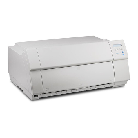
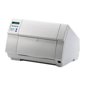
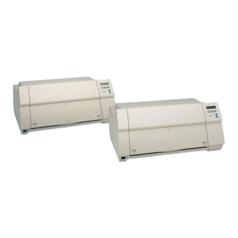
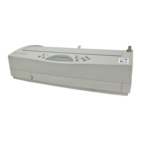
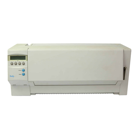
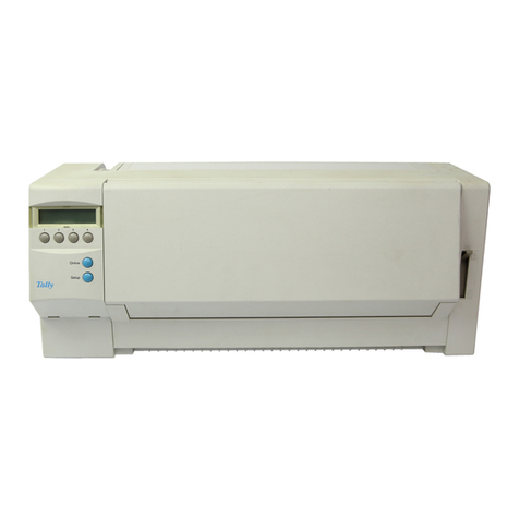
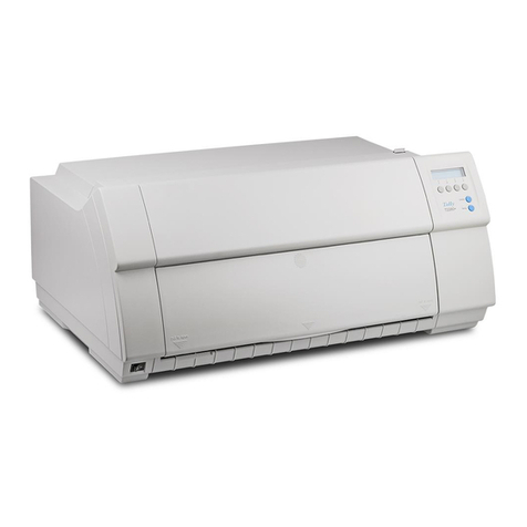
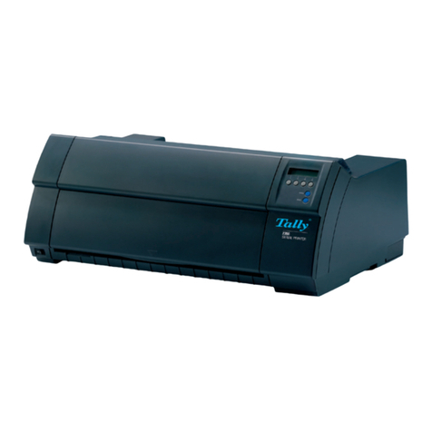
Tally T2265 SprintPro User manual

Maintenance Manual Matrix Printer
T2265
SprintPro
®
T2280
SprintPro
T2155
T2170

This page intentionally left blank

Table of contents
Chapter 1 Introduction . . . . . . . . . . . . . . . . . . . . . . . . . . . . . . . . . . . . . . . . . . . 1-1
Chapter 2 Specifications . . . . . . . . . . . . . . . . . . . . . . . . . . . . . . . . . . . . . . . . . 2-1
2.1 Printer Specifications . . . . . . . . . . . . . . . . . . . . . . . . . . . . . . . . . . 2-1
2.2 Interface Specifications . . . . . . . . . . . . . . . . . . . . . . . . . . . . . . . . . 2-5
2.3 Paper Specifications . . . . . . . . . . . . . . . . . . . . . . . . . . . . . . . . . . 2-6
2.4 Printer Dimensions . . . . . . . . . . . . . . . . . . . . . . . . . . . . . . . . . . . 2-8
Chapter 3 Functional Description . . . . . . . . . . . . . . . . . . . . . . . . . . . . . . . . . . . 3-1
3.1 General . . . . . . . . . . . . . . . . . . . . . . . . . . . . . . . . . . . . . . . . . . 3-1
3.1.1 Printhead . . . . . . . . . . . . . . . . . . . . . . . . . . . . . . . . . . . . . . . . . 3-1
3.1.2 Power Supply . . . . . . . . . . . . . . . . . . . . . . . . . . . . . . . . . . . . . . . 3-1
3.1.3 Ribbon . . . . . . . . . . . . . . . . . . . . . . . . . . . . . . . . . . . . . . . . . . 3-1
3.1.4 Data Transfer . . . . . . . . . . . . . . . . . . . . . . . . . . . . . . . . . . . . . . . 3-2
3.1.5 Monitoring . . . . . . . . . . . . . . . . . . . . . . . . . . . . . . . . . . . . . . . . 3-2
3.2 Mechanical Functions . . . . . . . . . . . . . . . . . . . . . . . . . . . . . . . . . 3-3
3.2.1 Head/Platen Clearance . . . . . . . . . . . . . . . . . . . . . . . . . . . . . . . . . . 3-3
3.2.2 Shift Friction ➜Tractor . . . . . . . . . . . . . . . . . . . . . . . . . . . . . . . . . . 3-5
3.2.3 Monitoring Light Barrier ,,Path Selection“ . . . . . . . . . . . . . . . . . . . . . . . . . 3-10
3.2.4 Position of the Wheels . . . . . . . . . . . . . . . . . . . . . . . . . . . . . . . . . . 3-11
3.2.5 Paperways . . . . . . . . . . . . . . . . . . . . . . . . . . . . . . . . . . . . . . . . 3-13
3.3 Electronic Functions . . . . . . . . . . . . . . . . . . . . . . . . . . . . . . . . . . 3-15
3.3.1 Main Board . . . . . . . . . . . . . . . . . . . . . . . . . . . . . . . . . . . . . . . . 3-18
3.3.1.1 Description of the Switching Power Supply . . . . . . . . . . . . . . . . . . . . . . . 3-18
3.3.1.2 Driver Section . . . . . . . . . . . . . . . . . . . . . . . . . . . . . . . . . . . . . . 3-19
3.3.1.3 Needle Driver . . . . . . . . . . . . . . . . . . . . . . . . . . . . . . . . . . . . . . . 3-19
3.3.2 Panel . . . . . . . . . . . . . . . . . . . . . . . . . . . . . . . . . . . . . . . . . . . 3-21
3.3.3 Bidirectional Centronics Interface . . . . . . . . . . . . . . . . . . . . . . . . . . . . 3-22
3.3.3.1 Interface Board Option/Modular . . . . . . . . . . . . . . . . . . . . . . . . . . . . . 3-24
3.3.3.2 Shared Interface . . . . . . . . . . . . . . . . . . . . . . . . . . . . . . . . . . . . . 3-26
3.3.3.3 TTY Interface 20 mA . . . . . . . . . . . . . . . . . . . . . . . . . . . . . . . . . . . 3-27
3.3.3.4 RS422/V11, SS97 . . . . . . . . . . . . . . . . . . . . . . . . . . . . . . . . . . . . 3-28
3.3.4 Connection Board . . . . . . . . . . . . . . . . . . . . . . . . . . . . . . . . . . . . 3-29
3.3.5 Printhead Sensor Board . . . . . . . . . . . . . . . . . . . . . . . . . . . . . . . . . 3-30
3.3.6 Interlock Switch . . . . . . . . . . . . . . . . . . . . . . . . . . . . . . . . . . . . . . 3-30
3.3.7 Double Sensor and Paper Motion Sensor . . . . . . . . . . . . . . . . . . . . . . . . 3-30
3.3.8 Sensor Sheetfeeder and 3rd Tractor . . . . . . . . . . . . . . . . . . . . . . . . . . . 3-30
3.3.9 Motor Driver . . . . . . . . . . . . . . . . . . . . . . . . . . . . . . . . . . . . . . . 3-31
3.3.10 Carriage Motor . . . . . . . . . . . . . . . . . . . . . . . . . . . . . . . . . . . . . . 3-32
3.3.11 Vertical Motor . . . . . . . . . . . . . . . . . . . . . . . . . . . . . . . . . . . . . . . 3-32
3.3.12 Color Motor (Option) . . . . . . . . . . . . . . . . . . . . . . . . . . . . . . . . . . . 3-32
3.3.13 Sheetfeeder Motor (Option) . . . . . . . . . . . . . . . . . . . . . . . . . . . . . . . 3-32
Table of contents

3.3.14 Paper Thickness Motor . . . . . . . . . . . . . . . . . . . . . . . . . . . . . . . . . 3-32
3.3.15 Function Select Motor . . . . . . . . . . . . . . . . . . . . . . . . . . . . . . . . . . 3-33
3.3.16 Paper Thickness Sensor (AGA) . . . . . . . . . . . . . . . . . . . . . . . . . . . . . 3-34
3.3.17 Optional Rear Tractor . . . . . . . . . . . . . . . . . . . . . . . . . . . . . . . . . . 3-35
3.3.18 Paper Motion Sensor . . . . . . . . . . . . . . . . . . . . . . . . . . . . . . . . . . 3-35
3.3.19 Function Select Sensor . . . . . . . . . . . . . . . . . . . . . . . . . . . . . . . . . 3-35
3.3.20 Option Recognition . . . . . . . . . . . . . . . . . . . . . . . . . . . . . . . . . . . 3-36
3.3.21 Sensor Automatic Front Insertion (Future Enhance- ment, Option) . . . . . . . . . . . 3-36
3.3.22 Printhead . . . . . . . . . . . . . . . . . . . . . . . . . . . . . . . . . . . . . . . . . 3-37
3.3.23 Additional fonts . . . . . . . . . . . . . . . . . . . . . . . . . . . . . . . . . . . . . 3-38
3.3.23.1 Non-scalable fonts . . . . . . . . . . . . . . . . . . . . . . . . . . . . . . . . . . . . 3-38
3.3.23.2 Scalable fonts . . . . . . . . . . . . . . . . . . . . . . . . . . . . . . . . . . . . . . 3-40
3.3.23.3 Barcodes . . . . . . . . . . . . . . . . . . . . . . . . . . . . . . . . . . . . . . . . . 3-42
3.3.24 Theory of Adjusting Print- head Temperature T2170 and T2280 only . . . . . . . . . . 3-43
3.4 Loading Firmware (principle) . . . . . . . . . . . . . . . . . . . . . . . . . . . . . 3-44
Chapter 4 Testmodes and Troubleshooting . . . . . . . . . . . . . . . . . . . . . . . . . . . . . 4-1
4.1 Test Functions . . . . . . . . . . . . . . . . . . . . . . . . . . . . . . . . . . . . . . 4-1
4.1.1 ASCII Tree . . . . . . . . . . . . . . . . . . . . . . . . . . . . . . . . . . . . . . . . . 4-2
4.1.2 Interfacetest (Hex-Dump) . . . . . . . . . . . . . . . . . . . . . . . . . . . . . . . . . 4-2
4.2 Troubleshooting . . . . . . . . . . . . . . . . . . . . . . . . . . . . . . . . . . . . . 4-3
4.2.1 Error Messages in the LCD Display . . . . . . . . . . . . . . . . . . . . . . . . . . . . 4-3
4.2.2 Further Messages in the LCD Display . . . . . . . . . . . . . . . . . . . . . . . . . . . 4-6
4.2.3 Printer Malfunctions without any Message at the LCD Display . . . . . . . . . . . . . . 4-7
4.2.4 Failure Analysis . . . . . . . . . . . . . . . . . . . . . . . . . . . . . . . . . . . . . 4-10
4.3 Monitoring Functions . . . . . . . . . . . . . . . . . . . . . . . . . . . . . . . . . 4-11
4.4 Caring, Lubrication and Maintenance . . . . . . . . . . . . . . . . . . . . . . . . . 4-13
4.5 Monitoring of Thermo-ASIC and Printhead . . . . . . . . . . . . . . . . . . . . . 4-14
4.5.1 Calibrating Values of Thermo-ASIC and Printhead (T2170/T2280 only) . . . . . . . . 4-14
4.6 Display Message “Hardware Alarm” . . . . . . . . . . . . . . . . . . . . . . . . . 4-15
4.7 Ignore Printhead . . . . . . . . . . . . . . . . . . . . . . . . . . . . . . . . . . . . 4-17
4.8 Printing without Top Cover . . . . . . . . . . . . . . . . . . . . . . . . . . . . . . 4-18
4.9 Loading optional firmware or character generator . . . . . . . . . . . . . . . . . 4-19
Chapter 5 Instructions for Disassembly and Assembly . . . . . . . . . . . . . . . . . . . . . . 5-1
5.1 Replacing Casing . . . . . . . . . . . . . . . . . . . . . . . . . . . . . . . . . . . . . 5-2
5.1.1 Replacing Top Case . . . . . . . . . . . . . . . . . . . . . . . . . . . . . . . . . . . . 5-2
5.1.2 Replacing Bottom Case . . . . . . . . . . . . . . . . . . . . . . . . . . . . . . . . . . 5-5
5.2 Printhead . . . . . . . . . . . . . . . . . . . . . . . . . . . . . . . . . . . . . . . . . 5-6
5.2.1 Removing the Printhead . . . . . . . . . . . . . . . . . . . . . . . . . . . . . . . . . . 5-6
5.2.2 Installing the Printhead . . . . . . . . . . . . . . . . . . . . . . . . . . . . . . . . . . 5-7
5.3 Replacing Electronic Parts . . . . . . . . . . . . . . . . . . . . . . . . . . . . . . . 5-8
5.3.1 Replacing Optional Interface . . . . . . . . . . . . . . . . . . . . . . . . . . . . . . . 5-8
5.3.2 Replacing Main Board . . . . . . . . . . . . . . . . . . . . . . . . . . . . . . . . . . . 5-9
Table of contents
5.3.3 Dismount Main Electronic . . . . . . . . . . . . . . . . . . . . . . . . . . . . . . . . 5-9
5.3.4 Replacing the AGA Assy . . . . . . . . . . . . . . . . . . . . . . . . . . . . . . . . . 5-10
5.3.5 Replacing Carriage Adapter . . . . . . . . . . . . . . . . . . . . . . . . . . . . . . . 5-10
5.3.6 Replacing Motor Driver (Color Option) . . . . . . . . . . . . . . . . . . . . . . . . . . 5-12
5.3.7 Replacing Connector Board . . . . . . . . . . . . . . . . . . . . . . . . . . . . . . . 5-12
5.4 Replacing Motors . . . . . . . . . . . . . . . . . . . . . . . . . . . . . . . . . . . . 5-13
5.4.1 Replacing Carriage (DC) Motor . . . . . . . . . . . . . . . . . . . . . . . . . . . . . 5-13
5.4.2 Replacing Stepper Motors . . . . . . . . . . . . . . . . . . . . . . . . . . . . . . . . 5-13
5.4.3 Replacing Vertical Stepper . . . . . . . . . . . . . . . . . . . . . . . . . . . . . . . . 5-13
5.5 Replacing Sensor Parts . . . . . . . . . . . . . . . . . . . . . . . . . . . . . . . . . 5-14
5.5.1 Replacing Double Sensor: Front Insertion / Paper Position and Paper Motion Sensor . 5-14
5.5.2 Replacing Sheetfeeder Sensor . . . . . . . . . . . . . . . . . . . . . . . . . . . . . 5-15
5.5.3 Replacing Interlock Sensor . . . . . . . . . . . . . . . . . . . . . . . . . . . . . . . . 5-16
5.6 Replace Transverse Paper Guide . . . . . . . . . . . . . . . . . . . . . . . . . . . 5-17
5.7 Ribbon Drive . . . . . . . . . . . . . . . . . . . . . . . . . . . . . . . . . . . . . . . 5-18
5.7.1 Replacing Ribbon Drive . . . . . . . . . . . . . . . . . . . . . . . . . . . . . . . . . 5-18
5.7.2 Installing Ribbon Drive Set . . . . . . . . . . . . . . . . . . . . . . . . . . . . . . . . 5-19
5.8 Remove Carriage System . . . . . . . . . . . . . . . . . . . . . . . . . . . . . . . 5-20
5.9 Replacing Upper Friction Drive . . . . . . . . . . . . . . . . . . . . . . . . . . . . 5-21
5.10 Replacing the Tractor Assy . . . . . . . . . . . . . . . . . . . . . . . . . . . . . . 5-22
5.11 Replacing Lower Friction Drive . . . . . . . . . . . . . . . . . . . . . . . . . . . . 5-23
5.12 Remove Incremental Stripe . . . . . . . . . . . . . . . . . . . . . . . . . . . . . . 5-24
5.13 Replacing Side Walls . . . . . . . . . . . . . . . . . . . . . . . . . . . . . . . . . . 5-25
5.14 Mounting Drive Wheel . . . . . . . . . . . . . . . . . . . . . . . . . . . . . . . . . 5-26
5.15 Remove Platen . . . . . . . . . . . . . . . . . . . . . . . . . . . . . . . . . . . . . 5-27
Chapter 6 Adjustments . . . . . . . . . . . . . . . . . . . . . . . . . . . . . . . . . . . . . . . . . . 6-1
6.1 Mechanical Adjustments . . . . . . . . . . . . . . . . . . . . . . . . . . . . . . . . 6-1
6.1.1 Tension of the Toothed Belt . . . . . . . . . . . . . . . . . . . . . . . . . . . . . . . 6-1
6.1.2 Adjustment of Head / Platen Gap . . . . . . . . . . . . . . . . . . . . . . . . . . . . 6-2
6.1.3 Adjusting Parallelism Printhead/Platen . . . . . . . . . . . . . . . . . . . . . . . . . . 6-4
6.2 Electrical Adjustments . . . . . . . . . . . . . . . . . . . . . . . . . . . . . . . . . 6-6
6.2.1 Interface Jumper Settings . . . . . . . . . . . . . . . . . . . . . . . . . . . . . . . . 6-6
6.2.1.1 Shared Interface (Option) (046 752) . . . . . . . . . . . . . . . . . . . . . . . . . . . 6-6
6.2.1.2 TTY-Interface 20 mA Current Loop (Option) (046 755) . . . . . . . . . . . . . . . . . 6-8
6.2.1.3 Interface RS422 (047 144) SS 97 (047 145) (Option) . . . . . . . . . . . . . . . . . . 6-9
6.2.1.4 Main Controller . . . . . . . . . . . . . . . . . . . . . . . . . . . . . . . . . . . . . . 6-10
6.2.1.5 Firmware . . . . . . . . . . . . . . . . . . . . . . . . . . . . . . . . . . . . . . . . . 6-11
6.2.1.6 Non standard controller . . . . . . . . . . . . . . . . . . . . . . . . . . . . . . . . . . 6-11
6.3 Soft Adjustments . . . . . . . . . . . . . . . . . . . . . . . . . . . . . . . . . . . . 6-12
6.3.1 Setting of Head Temperature (Reference value) (T2170/T2280 only) . . . . . . . . . . 6-12
6.3.2 Adjustment of AGA . . . . . . . . . . . . . . . . . . . . . . . . . . . . . . . . . . . 6-13
Table of contents
Chapter 7 Spare Parts and Schematics . . . . . . . . . . . . . . . . . . . . . . . . . . . . . . . . 7-1
7.1 Housing . . . . . . . . . . . . . . . . . . . . . . . . . . . . . . . . . . . . . . . . . . 7-2
7.2 Basic Printer . . . . . . . . . . . . . . . . . . . . . . . . . . . . . . . . . . . . . . . 7-4
7.3 Standard Tractor Assy . . . . . . . . . . . . . . . . . . . . . . . . . . . . . . . . . 7-10
7.4 AGA . . . . . . . . . . . . . . . . . . . . . . . . . . . . . . . . . . . . . . . . . . . 7-12
7.5 Connection Board/Cables . . . . . . . . . . . . . . . . . . . . . . . . . . . . . . . 7-12
7.6 Electronic Parts and Sensors . . . . . . . . . . . . . . . . . . . . . . . . . . . . . 7-15
7.6.1 Mainboard Complete Standard Spare Assy . . . . . . . . . . . . . . . . . . . . . . . 7-15
7.6.2 Carriage Adapter Assy . . . . . . . . . . . . . . . . . . . . . . . . . . . . . . . . . . 7-16
7.6.3 Sensor Papermotion/End . . . . . . . . . . . . . . . . . . . . . . . . . . . . . . . . 7-17
7.6.4 Sensor ASF/3rd Tractor . . . . . . . . . . . . . . . . . . . . . . . . . . . . . . . . . 7-17
7.6.5 Sensor Interlock . . . . . . . . . . . . . . . . . . . . . . . . . . . . . . . . . . . . . 7-17
7.6.6 Sensor Funciton Selection . . . . . . . . . . . . . . . . . . . . . . . . . . . . . . . . 7-18
7.6.7 AGA Sensor . . . . . . . . . . . . . . . . . . . . . . . . . . . . . . . . . . . . . . . 7-18
7.6.8 Horizontal Sensor . . . . . . . . . . . . . . . . . . . . . . . . . . . . . . . . . . . . 7-18
7.6.9 Non Standard Controller Parts . . . . . . . . . . . . . . . . . . . . . . . . . . . . . . 7-18
7.7 Panel . . . . . . . . . . . . . . . . . . . . . . . . . . . . . . . . . . . . . . . . . . 7-19
7.8 PMS + Double Sensor . . . . . . . . . . . . . . . . . . . . . . . . . . . . . . . . . 7-20
7.9 Sensor Sheet Feeder and Rear Tractor . . . . . . . . . . . . . . . . . . . . . . . . 7-21
7.10 Option Recogition . . . . . . . . . . . . . . . . . . . . . . . . . . . . . . . . . . . 7-22
7.11 Sens Function Select . . . . . . . . . . . . . . . . . . . . . . . . . . . . . . . . . . 7-23
7.12 AFI Automatic Front Insertion . . . . . . . . . . . . . . . . . . . . . . . . . . . . . 7-24
7.13 Modular Interfaces . . . . . . . . . . . . . . . . . . . . . . . . . . . . . . . . . . . 7-25
7.13.1 Shared Interface Cx/RS232 (Option) . . . . . . . . . . . . . . . . . . . . . . . . . . 7-25
7.13.2 Current Loop Interface 20 mA (Option 046 755) . . . . . . . . . . . . . . . . . . . . . 7-27
7.14 Serial Interface . . . . . . . . . . . . . . . . . . . . . . . . . . . . . . . . . . . . . 7-28
Chapter 8 Sheet Feeder Mechanic . . . . . . . . . . . . . . . . . . . . . . . . . . . . . . . . . . . . 8-1
8.1 Specifications . . . . . . . . . . . . . . . . . . . . . . . . . . . . . . . . . . . . . . . 8-1
8.2 Assembly/ Disassembly . . . . . . . . . . . . . . . . . . . . . . . . . . . . . . . . . 8-3
8.2.1 Sheetfeeder . . . . . . . . . . . . . . . . . . . . . . . . . . . . . . . . . . . . . . . . 8-3
8.2.2 Mounting Gear Block . . . . . . . . . . . . . . . . . . . . . . . . . . . . . . . . . . . 8-3
8.3 Spare Parts and Schematics . . . . . . . . . . . . . . . . . . . . . . . . . . . . . . . 8-4
8.4 ASF/Sheetfeeder, Gear Block . . . . . . . . . . . . . . . . . . . . . . . . . . . . . . 8-6
Chapter 9 Face Down (Option) . . . . . . . . . . . . . . . . . . . . . . . . . . . . . . . . . . . . . . 9-1
9.1 Specification . . . . . . . . . . . . . . . . . . . . . . . . . . . . . . . . . . . . . . . 9-1
9.2 Functional Description . . . . . . . . . . . . . . . . . . . . . . . . . . . . . . . . . . 9-1
9.3 Spare Parts . . . . . . . . . . . . . . . . . . . . . . . . . . . . . . . . . . . . . . . . 9-2
Table of contents

Chapter 10 Rear Tractor (Option, 2T Model) . . . . . . . . . . . . . . . . . . . . . . . . . . . . . 10-1
10.1 Specifications . . . . . . . . . . . . . . . . . . . . . . . . . . . . . . . . . . . . . . 10-1
10.2 Tractor Complete . . . . . . . . . . . . . . . . . . . . . . . . . . . . . . . . . . . . 10-2
Chapter 11 Cutting Device (Option) . . . . . . . . . . . . . . . . . . . . . . . . . . . . . . . . . . . 11-1
11.1 Specifications . . . . . . . . . . . . . . . . . . . . . . . . . . . . . . . . . . . . . . 11-1
11.2 Spare Parts and Schematics . . . . . . . . . . . . . . . . . . . . . . . . . . . . . . 11-3
11.2.1 Mechanical Components . . . . . . . . . . . . . . . . . . . . . . . . . . . . . . . . 11-3
11.2.2 Maintenance and Adjustments . . . . . . . . . . . . . . . . . . . . . . . . . . . . . . 11-3
Chapter 12 2nd- (Front-) Tractor (option) . . . . . . . . . . . . . . . . . . . . . . . . . . . . . . . 12-1
Chapter 13 Color Option . . . . . . . . . . . . . . . . . . . . . . . . . . . . . . . . . . . . . . . . . . 13-1
Chapter 14 Printer Stand . . . . . . . . . . . . . . . . . . . . . . . . . . . . . . . . . . . . . . . . . . 14-1
Table of contents

This page intentionally left blank

1 Introduction
The Matrix Printers have been developed for professional applications in all
environments. They meet the highest possible technical standards, and with proper
use, they should provide many years of trouble-free operation.
High-performance print qualities as well as operation with fanfold paper and cut
sheets from front can be chosen.
The following print qualities are available:
High Speed Draft Print Quality (HSQ)
Copy Draft Print Quality (DPQ Copy)
Draft Print Quality (DPQ)
Near Letter Quality (NLQ)
Letter Quality (LQ)
For details see chapter
Specifictions
.
The electronic part controlled by a microcomputer operates the needle printhead,
menu programming, and interface.
All elements of the printer control are arranged on printed circuit boards so that only
a few additional components are required such as
step motor for function select,
step motor for color option,
step motor for paper feed,
DC motor for carriage feed,
step motor for automatic gap adjust
The following options and features will further enhance the printer’s capabilities:
3rd tractor from rear (feature)
push tractor front (standard)
front cut sheet insertion (standard)
automatic gap adjustment (standard)
sheet feeder with two paper bins (option)
face down module for cut sheet feeder (option)
fonts (option)
automatic gap adjustment (standard)
multi-color ribbon (feature)
2nd push tractor front (option)
The manufacturer recommends the use of original accessories.
The use of others than original parts may reduce the performance of the printer and
cause defects on the printer. For errors caused by the use of others than original
accessories, your warranty become invalid.
Caution:
Activities described herein must only be performed by specially trained and
qualified service personnel! Harmful voltages can be touched.
STOP
Introduction
1-1

This page intentionally left blank

2 Specifications
2.1
Printer Specifications Printer system Serial impact matrix printer
1800 Hz
Printhead with 24 needles
∅0.25 mm bidirectional printing
Print speed and
character matrices T2155 T2170 T2265 T2280
cps cps cps cps cpi matrix
HSQ
(High Speed Quality) 650 800 10,0 12 x 10
720 880 12,0 12 x 10
900 1100 15,0 08 x 08*
900 1100 15,0 12 x 08
515 630 17,1 12 x 12
600 735 20,0 12 x 10
DPQ
(Data Print Quality) 550 700 600 700 10.0 12 x 12
660 840 720 840 12.0 12 x 10
825 1050 900 1050 15.0 12 x 08*
825 1050 900 1050 15.0 12 x 12
515 630 515 630 17.1 12 x 12
600 735 600 735 20.0 12 x 10
CPQ
(Copy Print Quality) 300 335 300 330 10.0 24 x 12
360 400 360 400 12.0 24 x 10
450 500 450 500 15.0 16 x 08*
450 500 450 500 15.0 24 x 08
260 285 260 285 17.1 24 x 12
300 335 300 335 20.0 24 x 10
NLQ
(Near Letter Quality) 200 245 200 245 10.0 24 x 18
240 295 240 295 12.0 24 x 15
300 370 300 370 15.0 16 x 12*
150 185 150 185 15.0 24 x 12
170 210 170 210 17.1 24 x 18
200 245 200 245 20.0 24 x 15
LQ
(Letter Quality) 100 120 100 120 10.0 24 x 36
120 145 120 145 12.0 24 x 30
150 185 150 185 15.0 16 x 24*
150 185 150 185 15.0 24 x 24
170 210 170 210 17.1 24 x 18
200 245 200 245 20.0 24 x 15
* Epson emulation only: superscript, subscript,
microscript and MTPL microscipt
Tab speed T2155 T2170 T2265 T2280
55 ips* 70 iips 65 ips 80 ips
* inch per second
Character pitch 5 / 6 / 7.5 / 8.6 / 10 / 12 / 15 / 17.1 / 20 cpi
Character size
Height 3.32 mm (incl. descenders)
Width 2.19 mm, max. 2.43 mm
Specifications Printer Specifications
2-1

Fonts
Standard Print qualities: HSQ (T2265/T2280 only), (Draft), CPQ (Copy
Draft) Near Letter Quality (NLQ), Letter Quality (LQ);
Fonts: Courier, Roman, Sanserif, OCR A + B (all resident in
NLQ und LQ);
DLL is standard, but not battery-buffered
Barcodes (standard) A 2/5 Matrix (default)
B 2/5 Industrial
C 2/5 Interleaved
D Code 11
E BCD Matrix
F Code 39
G Codabar
H EAN 8 (with HRI*)
I EAN 8 (without HRI)
J EAN 13 (with HRI)
K EAN 13 (without HRI)
L MSI/modified PLESSEY
M UPC A (with HRI)
N UPC A (without HRI)
O UPC E (with HRI)
P UPC E (without HRI)
Q Delta Distance (IBM)
R Code 128
S EAN 128
US-Postnet Barcode
Kix
Royal Mail Customer Barcode
Large Character Printing (LCP)
* HRI = human readable index
Emulations
Standard – MTPL (Tally Printer Language)
– Epson LQ-2550/LQ-2170
– IBM Proprinter XL24e/IBM XL24e + AGM
Optional on request
Resolution 60 to 360 dpi horizontal
90 to 360 dpi vertical
Print attributes in all
character pitches Double width, italics, right justification, shadowed, auto
centered, double height, bold, proportionally spaced,
underlined, overlined, superscript, subscript, heavy form
mode (T2265/T2280 only)
Self-test ASCII test, Hexdump, Fault display, Ribbon test
Printer buffer 128 Kbytes
Panel LCD display
2 x 16 digits
6 function keys:
– Online
– Setup
– 4 softkeys
Printer Specifications Specifications
2-2

Paper feed
Feed speed 10"/sec
1/6" (line feed) 35 ms
View position 10"/sec
Reverse motion Up to max. form length (22 inch),
max. 1/6 inch for automatic single sheet feeder
Printhead gap
Standard Automatic gap adjustment
Paper transport T2155/T2265 T2170/T2280
Standard – Tractor 1 with parking – Tractor 1 with parking
position position
– Single sheet via front – Tractor 3 with parking
insertion (friction rollers) position1)
– Single sheet via front
insertion (friction rollers)
Optional – Automatic single sheet – Automatic single sheet feeder
feeder rear (capacity: rear (capacity: 80 sheets per
80 sheets per feeder)2) feeder)2)
– Automatic single sheet – Automatic single sheet feeder
feeder front (capacity: front (capacity: 80 sheets per
80 sheets per feeder)3feeder)3
– Tractor 2 (front) – Tractor 2 (front)
1) 2T model only
2) cannot be used in conjunction with the autocut facility and the 2Tmodel
3) cannot be used in conjunction with Tractor 2
Features Color printing
Service life T2155/T2170 T2265/T2280
Printhead 400 millions/DPQ 500 millions/DPQ
12 x 12 matrix 12 x 12 matrix
Ribbon 20 million characters 20 million characters
Noise T2155/T2265 T2170/T2280
Sound pressure level
Sound power level
LPA = 53 dB (A) LPA = 55 dB (A)
LWAd = 69 dB (A) LWAd = 70 dB (A)
Continuous operation
Throughput (ECMA 132)
pages/month at DPQ
pages/hour1)
MTBF
T2155 T2170 T2265 T2280
> 28,000 > 36,000 > 40,000 > 50,000
> 500 >600 > 598 > 620
> 10,000 h; 100% DC
1) Print quality High Speed, matrix 120 x 180 dpi, fanfold paper
Mains voltage USA/Canada 120 V ±10%; 60 Hz ± 2%
Europe 230 V ±10%; 50/60 Hz ± 2%
Power consumption T2155/T2170 T2265/T2280
at 100% troughput: at 100% troughput:
60 VA 70 VA
when idling: 15 VA when idling:15 VA
Approvals UL listed, ULc Certification, CE-Certification, FCC Class B
Certification, VDE-GS Certification
Specifications Printer Specifications
2-3

Dimensions
Width 623 mm (25.52 inches)
Height 277 mm (10.9 inches)
Depth 430 mm (16.92 inches)
Weight 19 kg (38 pounds)
Environmental conditions
Operation
Temperature +10° to +35°C
Rel. humidity 16 to 73%
Climate IEC 721-3-7, class 7K1
Storage
Temperature -5° to +45°C
Rel. humidity 5 to 95%
Climate IEC 721-3-1, class 1K3
Transport
Temperature -40° to +70°C
Rel. humidity 5 to 95%
Climate IEC 721-3-2, class 2K4
Printer Specifications Specifications
2-4

2.2
Interface
Specifications Parallel interface bidirectional
Type of data transmission 8-bit parallel interface (Centronics compatible)
IEEE-1284; Nibble mode
Transmission rate Max. 30 KHz
Signal status Low: 0.0 V to +0.4 V
High: +2.4 V to +5.0 V
Connection cable Material AWG no. 28 at least
Length up to 2.5 m
Twisted-pair cable with double-shield,
acc. IEEE Std 1284 – 1294
Interface connections Printer side Amphenol 57-40360
(or compatible)
Cable side Amphenol 57-30360
(or compatible)
Serial interface
Type RS232C interface
Synchronization Asynchronous
Transmission rate 600 bauds to 19,200 bauds
Signal status OFF = Mark = log. 1 = -3 V to -15 V
ON = Space = log. 0 = +3 V to +15 V
Connection cable Length up to 15 m
Interface connections ITT Cannon connector, Series DB-25 S
Transmission protocol XON/XOFF, ENQ/STX, READY/BUSY, Robust
XON/XOFF, ACK/NAK, ETX/ACK
Capacity of data buffer 128 KB max.
Specifications Interface Specifications
2-5

2.3
Paper Specifications
Continuous paper tractor 1, Single part forms
Weight 60 to 120 g/m2
Width 3 to 16.5 inches 76 to 420 mm
Form length 3 to 22 inches 76 to 559 mm
Continuous paper, Multi part forms, tractor 1 (to be tested individually)
Number of copies 1 + 6
Weight of original 45 to 65 g/m2
Weight of copies 45 to 56 g/m2
Weight of bottom sheet 45 to 65 g/m2
Thickness (max.) 0.024 inches 0.6 mm
Width 3 to 16.5 inches 76 to 420 mm
Form length 3 to 17,7 inches 76 to 451 mm
Continuous paper tractor 3; Single part forms, 2T model only
Weight 60 to 120 g/m2
Width 4 to 16.5 inches 100 to 420 mm
Form length 3 to 12 inches 76 to 305 mm
Continuous paper Multi part forms, tractor 3 (to be tested individually!),
2T model only
Number of copies 1 + 1
Weight of original 45 to 65 g/m2
Weight of copies 45 to 56 g/m2
Weight of bottom sheet 45 to 65 g/m2
Thickness (max.) 0.011 inches 0.28 mm
Width 3 to 16 inches 76 to 406 mm
Form length 3 to 18 inches 76 to 459 mm
Envelope
Width 3 to 16.5 inches 76 to 420 mm
Length 3 to 12 inches 76 to 305 mm
Thickness 0.0125 inches 0.32 mm
Cut sheet insertion via front feed/manual single part forms
Weight 80 to 120 g/m2
Width 3 to 16.5 inches 76 to 420 mm
Form length 3 to 12 inches 76 to 305 mm
Paper Specifications Specifications
2-6

Multi part forms (to be tested individually!)
Number of copies
Standard printer
2T model
1 + 6
1 + 1
Weight of original 50 to 60 g/m2
Weight of copies 45 to 56 g/m2
Weight of bottom sheet 50 to 60 g/m2
Thickness (max.) 0.024 inches 0.6 mm
Width 3 to 16.5 inches 76 to 420 mm
Form length 3 to 12 inches 76 to 305 mm
Set of forms Sets of forms may be used only if the top edge is
bound. The binding edge should be as soft as
possible. A wavy binding edge may hamper the
smooth feeding of these sets. Multi-part forms have
to be inserted with the glued top facing down.
Multi-part forms should be tested for suitability.
Paper quality Light pulp paper of medium fine quality, paper
bearing the quality mark SM Post and photocopy
paper are suitable for use. Unsuitable are:
satin-finish or coated papers, imitation art papers,
and embossed papers.
Since paper as natural material reacts strongly to
environmental influences (e.g. humidity,
temperature), the place of storage should be
selected carefully. We recommend that this kind of
paper should be tested extensively before larger
quantities are acquired.
Should papers with a dark reverse side be used,
these should also be tested for their functionality.
Please pay attention to the use of infrared reflecting
colors, when acquiring these papers.
Specifications Paper Specifications
2-7

2.4
Printer Dimensions
623
36.5
128
432
3.5
280
42±5
49±5
42±5
62±5
60
110
377
376
509
183
189
522.5
30
30
43045
(out max)(out max)426
94
389
(2 in)(2 in)406
(1 in)(1 in)420
(out 1)(out 1)420
(3 in)(3 in)406
front
buttom
rear side
T2155/T2265, T2170/T2280 Outline DrawingT2155/T2265, T2170/T2280 Outline Drawing
line dimensioningline dimensioning
centre of footcentre of foot
all dimensionsall dimensions
in mmin mm
1:5
paperway inpaperway in
tractor 1 (main)tractor 1 (main)
paperway outpaperway out
all tractorsall tractors
paperway inpaperway in
tractor 3 (rear)tractor 3 (rear)
paper
deflection bowdeflection bow
paperway in tractor 2paperway in tractor 2
(front, top optional)(front, top optional)
paper guidepaper guide
bracket (tractor 3)bracket (tractor 3)
Printer Dimensions Specifications
2-8

3 Functional Description
3.1
General
3.1.1
Printhead The printhead is rated to more than 300.000 standard pages. The printer is
economical too: 12.000 standard letters are printed with one ribbon.
With our own word-wide patented 24 needle technology the printer also in speed
reaches the top region of its class, with its noise level being in the lower range. The
printer practically operates in conjunction with all known computer systems and
standard software.
3.1.2
Power Supply The power supply may be switched by the user externally from 120 V to 230 V. A
fuse (T4,00AH250V, UL) is provided to protect the power supply from hazardous
damages. It can be replaced without opening the printer.
3.1.3
Ribbon The quality of the printout is dependent on the quality of the ribbon. Therefore the
ribbon as well as the printhead are very important parts of your printer.
A used ribbon cannot deliver a satisfactory printout. To achive a long life duration for
the ribbon always use it in its full width. This will be achived by moving the ribbon up
and down during printing and rotating the ribbon in the infinite end ribbon cassette.
The ribbon is therefore satisfactory used and reaches a long life time.
With a color printer you must decide if a color ribbon for a color printout or a mono-
chrome ribbon for a one color printout is to be used.
In the first case the color ribbon, which can have up to four tracks, is vertically moved
in four steps in relation to the printhead, depending on the selected color.
If you want to achive a monochrome printout with a color printer, you should use a
monochrom ribbon and set the parameter “black” in the Setup menu “Color Opt.”.
The firmware moves the color ribbon, simular to a standard printer, in four vertical
levels. Because of this electrical control the monochrom ribbon is optimally used by a
color printer.
yellow
magenta
cyan
black
black track 1
black track 2
black track 3
black track 4
Mono ribbon 4 color ribbon
Functional Description General
3-1

3.1.4
Data Transfer The main difference between the serial and parallel interface is the form in which the
data bytes are transfered. The serial interface transfers bits in a row, one after the
other. Theoretically you only need three connections for this form of data transfer. In
the parallel interface the data transfer of the 8 bits (1 byte) is completed
simultaneously through 8 parallel connections. At least 11 connections between the
computer and the printer are necessary for this procedure.
With the parallel Centronics interface data up to 100.000 bytes /seconds theoretically
can be transfered. Actual the printer opperates with a maximum transfer frequency of
approx. 30.000 bytes/second. This “Data Flow”, depending on the adjustment of the
input buffer (0-128 KB) on your printer, can be temporarily stored.
3.1.5
Monitoring The most important functions are monitored with sensors, microswitches and
electrical monitoring circuits. These are constantly checked, processed by an internal
logic and indicated on the display.
To prevent an overheating of the printhead, 12 coils of the 24 electromagnets are
monitored. If the temperature reaches a value above 130 °C the speed of the printer
is automatically slowed down. As soon as the printhead has cooled the printer works
with high speed again.
If a coil becomes defective, this is recognized by the firmware and shown on the
display (Head defect, THS Error, Head Hot permanently).
For safety reasons the top cover is also monitored. If you should open the top cover
during printing operation, then the printout is momentary stopped (to avoid injuries).
When you close the cover again the printout is continued without loss of data.
General Functional Description
3-2
Other manuals for T2265 SprintPro
2
This manual suits for next models
3
Table of contents
Other Tally Printer manuals

Tally
Tally T9014 User manual

Tally
Tally T6090 User manual

Tally
Tally T9114 Installation guide

Tally
Tally XPRESS T9412i Installation instructions

Tally
Tally Dascom 1125 User manual

Tally
Tally T9112 User manual

Tally
Tally XPRESS T9412i User manual

Tally
Tally T2280 SprintPro User manual

Tally
Tally T6218 Configuration guide

Tally
Tally T2265plus User manual