T&S B-0695 User manual
Installationand
Maintenance
Instructions
B-0695 ServiceSink
FittingswithConcealed
By-PassMixingValves
Deutsch: Installations- und
Wartungsanleitungen
Español: la Instalación y las
Instruccionesde
Mantenimiento
Français: lesInstructions
d’Installation et
d’Entretien
Limited One Year Warranty
T&Swarrantstotheoriginalpurchaser(otherthan
forpurposesofresale)thatsuchproductisfreefrom
defectsinmaterialandworkmanshipforaperiodof
one(1)yearfromthedateofpurchase. Duringthis
one-yearwarrantyperiod, iftheproductis foundto
bedefective,T&S shall,at itsoptions, repairand/
orreplaceit. Toobtainwarrantyservice,products
mustbereturnedto...
T&SBrassandBronzeWorks,Inc.
Attn: WarrantyRepairDepartment
2SaddlebackCove
TravelersRest,SC 29690
Shipping,freight,insurance,andothertranspor-
tationchargesoftheproducttoT&Sandthereturn
ofrepairedorreplacedproducttothepurchaserare
theresponsibilityofthepurchaser. Repairand/or
replacementshallbemadewithinareasonabletime
afterreceiptbyT&Softhereturned product. This
warrantydoesnotcoverItemswhichhavereceived
secondaryfinishingorhavebeenalteredormodi-
fiedafterpurchase, orfordefectscausedbyphysi-
calabuseto ormisuseoftheproduct,orshipment
oftheproducts.
Anyexpresswarrantynotprovidedherein,and
anyremedyforBreachofContractwhichmightarise,
is hereby excluded and disclaimed. Any implied
warrantiesofmerchantabilityorfitnessforaparticu-
larpurposearelimitedtooneyearinduration. Under
no circumstances shall T&S be liable for loss of
useor anyspecialconsequentialcosts,expenses
ordamages.
Somestatesdonotallowlimitationsonhowlong
andimpliedwarrantylastsortheexclusionorlimi-
tationof incidentalorconsequentialdamages,so
theabovelimitationsorexclusionsmay not apply
toyou. Specificrightsunderthiswarrantyandother
rightsvaryfromstatetostate.
P/N: 098-005910-45 Rev.2
Date: 980504
Drawn: CW
Checked: MAB 7-23-98
Approved: MVW 7-23-98

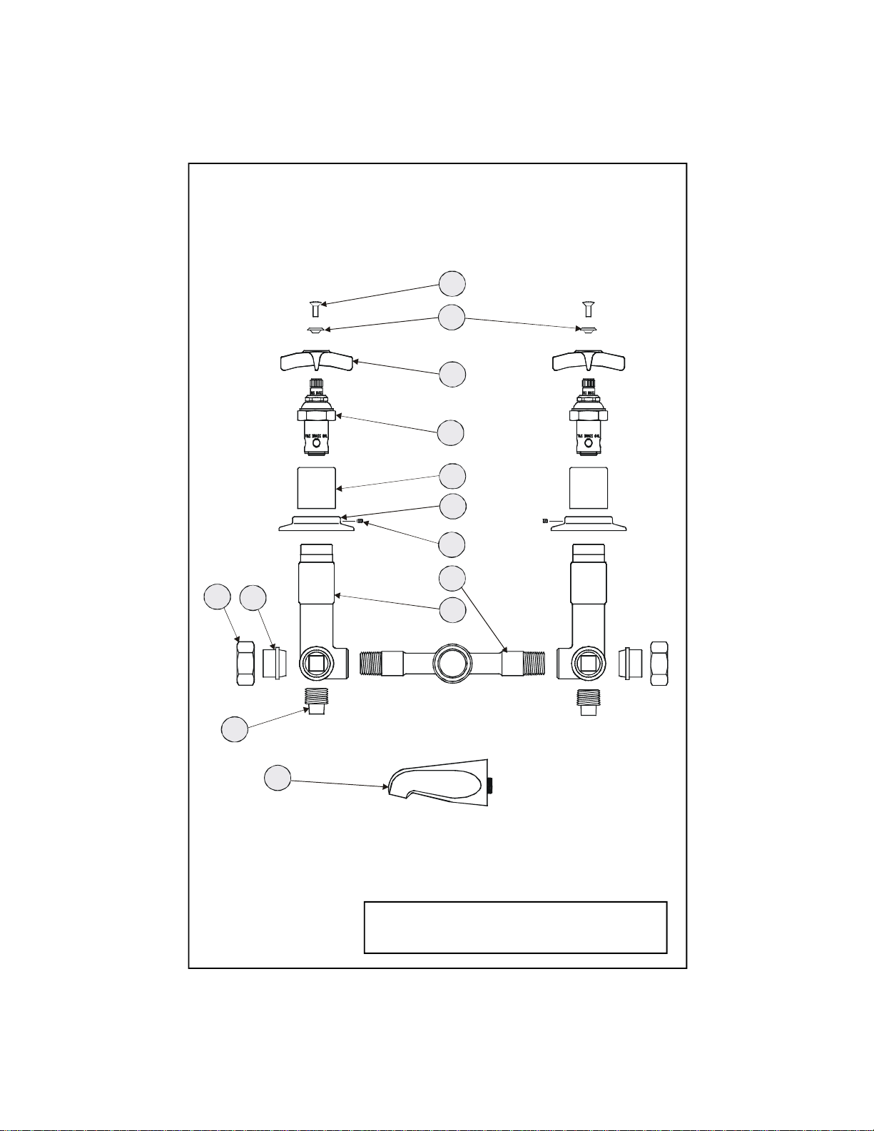
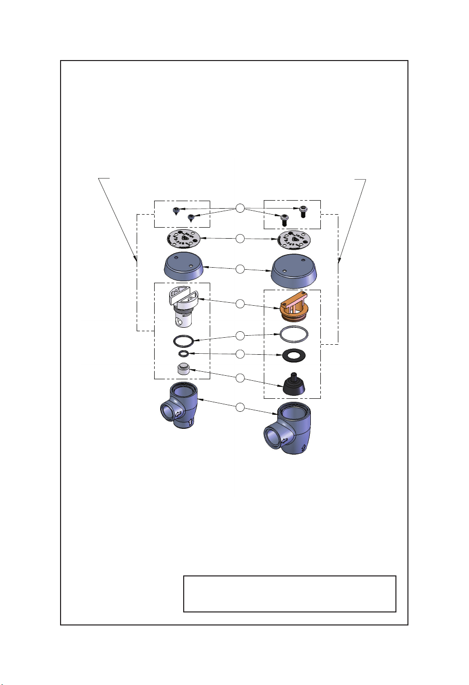
Exploded View
*Some items are listed for instructional purposes
and may not be sold as separate parts.
7
1
12
15
23
13
19
18
17
16
14
4
6985
10
11

Part Number Guide
Vacuum Breaker
1Asm, Vacuum Breaker B-0929-A
2Asm, Coupling Flange 002893-40
3Washer, Coupling Nut 001019-45
Mixing Valve Assembly
4Asm, By-Pass Mixing Valve B-1035
5Body, Valve *
6Asm, Spindle (Eterna) Hot 005960-40
7Escutcheon Tube *
8Escutcheon *
9Set Screw, Escutcheon Flange *
10 Loose Key Stop 009745-45
11 Nipple, Close 1/2" *
Nozzle Assembly w/ Brace
19 Asm, Nozzle w/ Brace B-0671-POL
12 Flange 000013-40
13 Asm, Nozzle *
14 Asm, Upper Nozzle Support 009546-40
15 Support Rod *
16 Flange, Support *
17 Roll Pin *
18 Screw, Wall Mount 000915-45

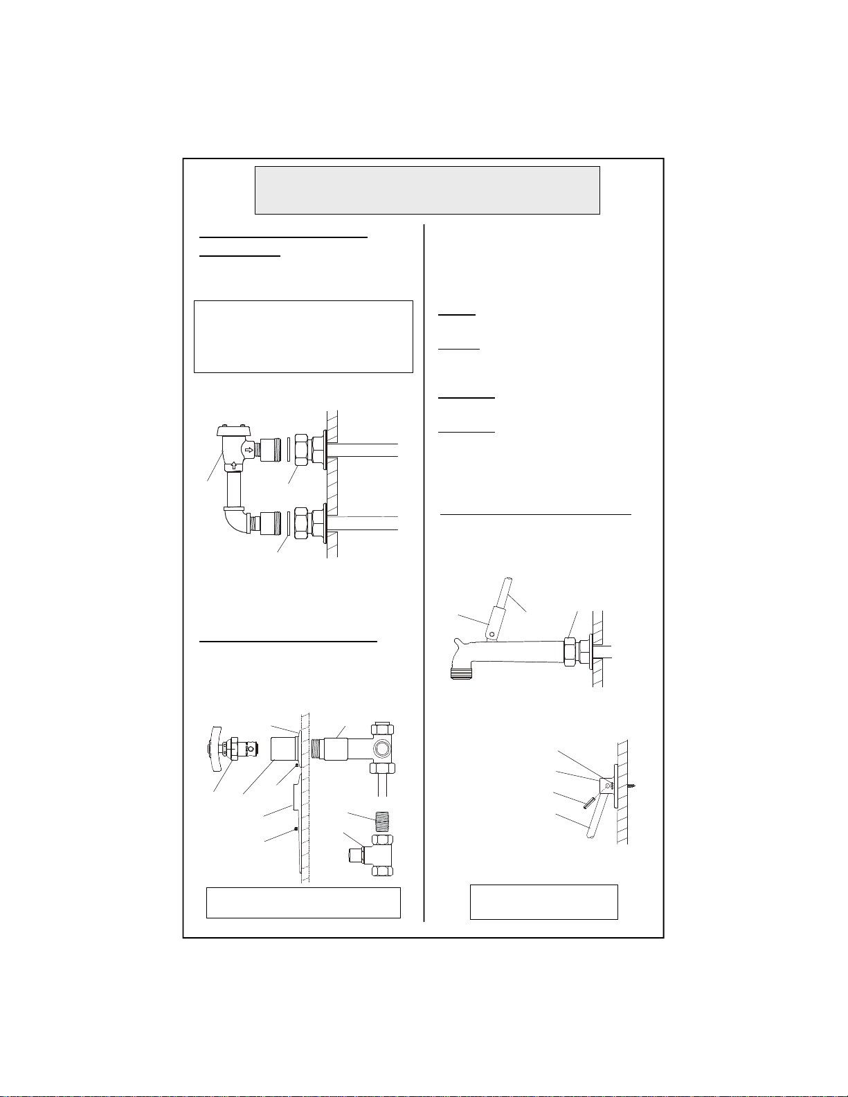
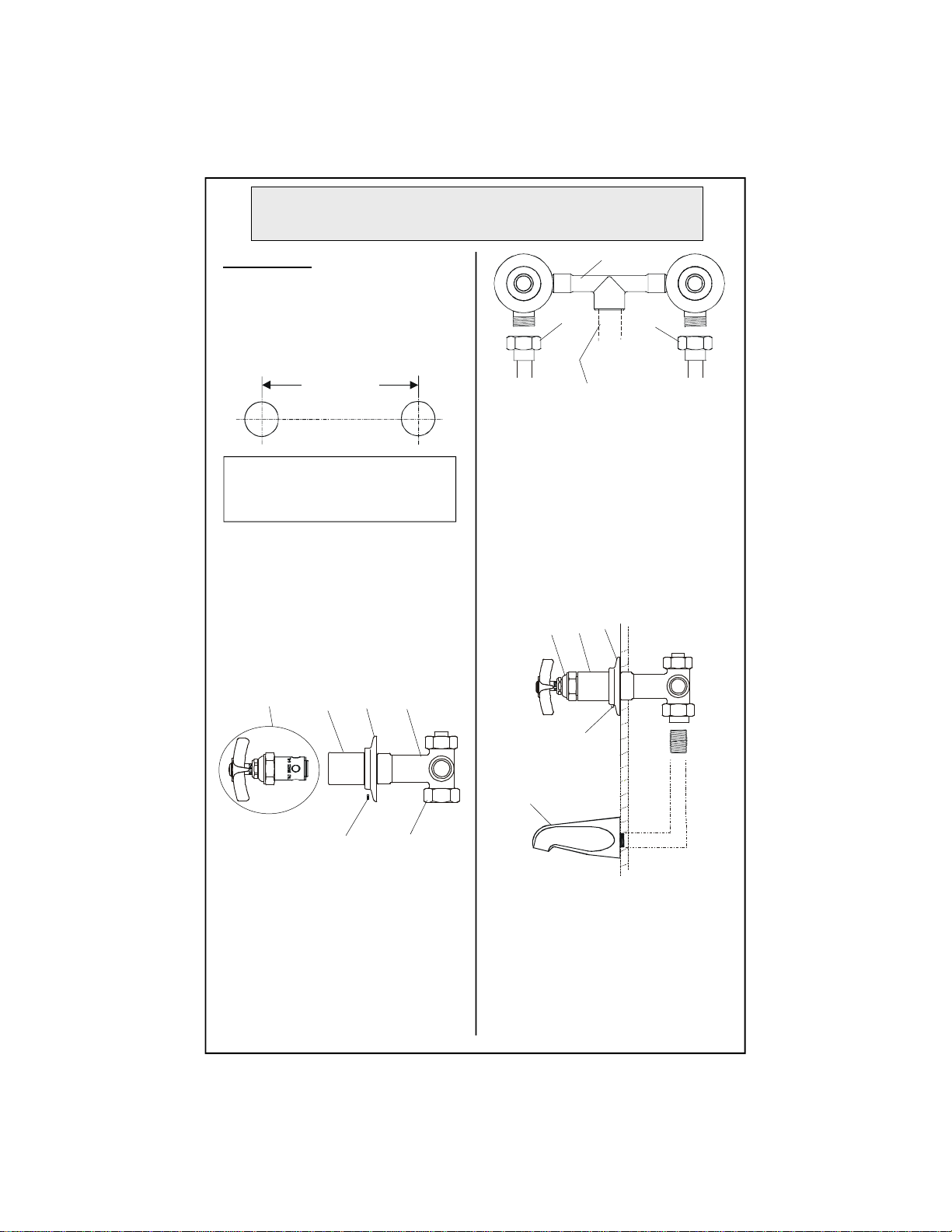
General Instructions
Installation: (Vacuum Breaker)
1. Drill holes 3-3/4” center-to-center in
wall where you will be installing no.1.
Note: Please consult applicable
plumbing codes for proper installed
height of no.1over outlet of no.13.
2. Remove no.3from no.1, install no.3
onto piping.
3. Reattach no.1to no.3, making sure
no.2is in place and tighten with a
wrench.
Installation: (Faucet Body)
4.After unpackingno.4,remove no.6,
no.7, no.8and no.9fromno.5.
(Loosen no.8at base of no.9, slide
both off no.5.)
5.(For B-0695ST andB-0696 ST
models, add no.10 by using no.11 to
join the couplings together.)
Make connections to no.4:
B-0695: 1/2” IPS (Iron Pipe Size) female
union inlets; 1/2” close nipples.
B-0696: 5/8” union inlets; must solder
copper piping to inlets.
B-0695 ST: use B-0416 stops; 1/2” NPT
(National Pipe Thread) piping.
B-0696 ST: installer must supply 5/8”
solder joint to 1/2” NPT (National Pipe
Thread) adapter in order to attach supply
lines to no.10.
1
outlet
inlet
2
3
wall
678
8
5
11
10
wall
9
9
Use no.10 and no.11 for B-0695 ST
and B-0696 ST models
inlet
supply
line
15
13
Installation: Nozzle
6. Attach no.12, onto supply pipe;
screw no.15 into no.13 attachment.
12
7. Mark holes on wall for attachment
of no.16; use provided no.18 to
secure no.16 to wall.
8. Insert no.17 into hole of no.16.
18
16
17
15
9. Turn on water and check for leaks.
Seeflowdiagramonpage8.

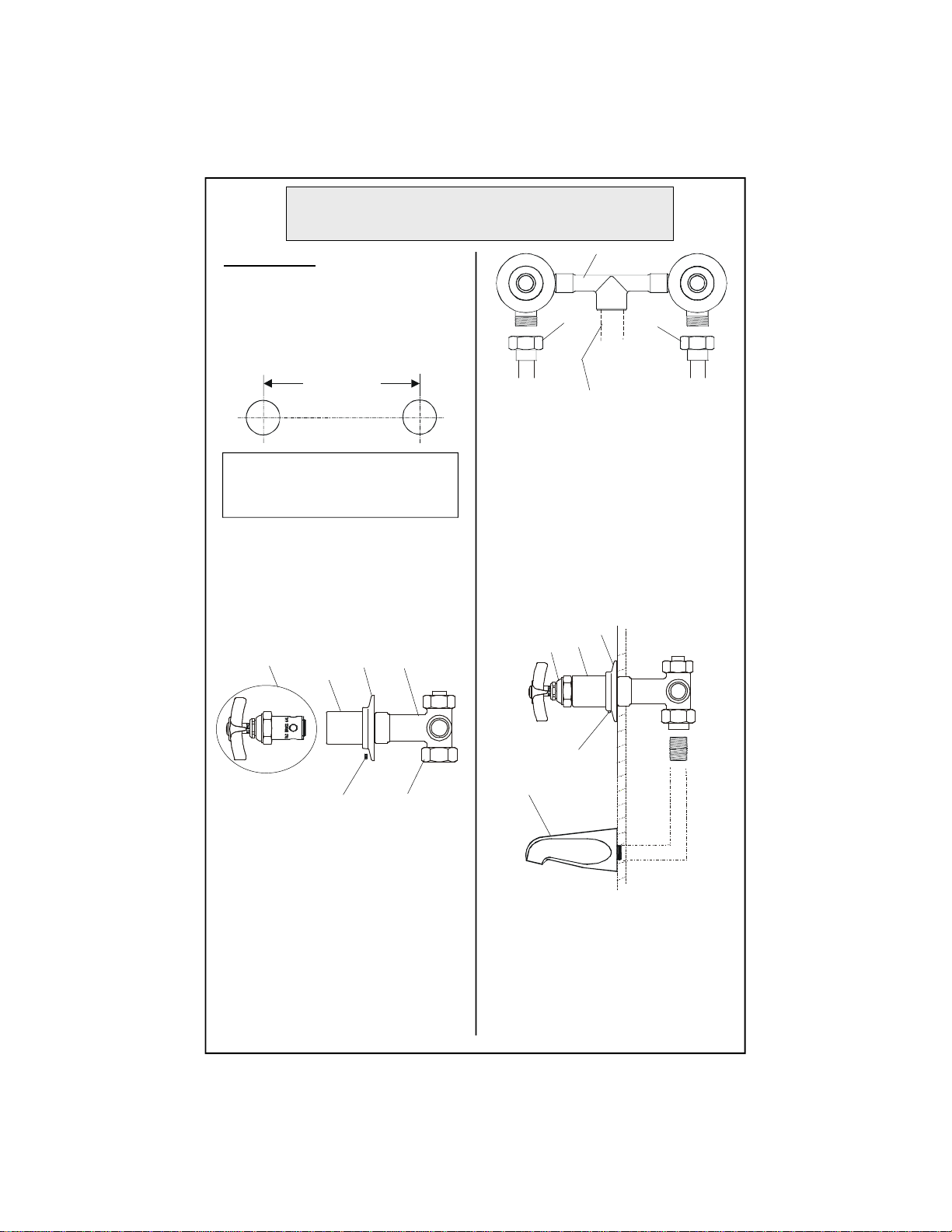
Instrucciones
Generales
Instalación: (Anti-sifón)
1. Perfore huecos de 9.5cm de centro a
centro en la pared donde la parte No.1
seráinstalada.
Nota: Por favor consulte codigos
aplicables de plomería para la apropiada
altura de instalación de la parte No.1
sobre el surtido de la parte No.13.
2. Remueva la parte No.3de la parte
No.1, instale la parte No.3enla
tubería.
3.Reemplazela parte No.1a la parte
No.3, asegurandose que la parte No.2
esté en su sitido y aprete con una
llave.
Instalación: (Canilla)
4. Después de desempacar la parte
No.4, remueva las partes No.6, No.7y
No.8da la parte No.5. (Afloje la parte
No.8 a la base de la parte No.9, deslize
ambos de la parte No.5.)
5.(Para modelosB-0695ST yB-0696
ST, agrege la parte No.10 usando la
parte No.11 para unir los enganches.)
Para Hacer Conecciones a la parte No.4:
B-0695: 1/2” IPS (Tamaño de tubería de
hierro) entradas de uniones femeninas
tubo enrroscado corto de 1/2”.
B-0696: Uniones de entrada de 5/8” tiene
que soldar tubería de cobre a las entradas.
B-0695 ST: Use pares modelo B-0416;
tubería NPT (Rosca Nacional De Tubo).
B-0696 ST: El instalador debe de surtir la
coyuntura soldada de 5/8” al adaptador de
1/2” NPT (Rosca Nacional De Tubo) en
orden de unir las lineas de surtido a la
parte No.10.
1
Salida
Entrada
2
3
pared
678
8
5
11
10
pared
9
9
Use las partes No.
10 y 11 para los
modelos B-0695
ST y B-0696 ST.
Entrada
Instalación: Boquilla
Linea
de
Surtido
15
13
6. Junte la parte No.12 a la linea de
surtido; atornille la parte No.15
dentro del encaje de la parte No.13.
12
7. Para colocar la parte No.16 marque
los huecos en la pared; para mantener
la parte No.16 use la parte No.18 que
esta surtida. 18
16
17
15
9.Abra la fuente de agua e
inspeccione por filtraciones.
Vea el diagrama de
desagüe en la pagina 8.
8. Insarte la
parte No.17
dentro del
hueco de la
parteNo.16.
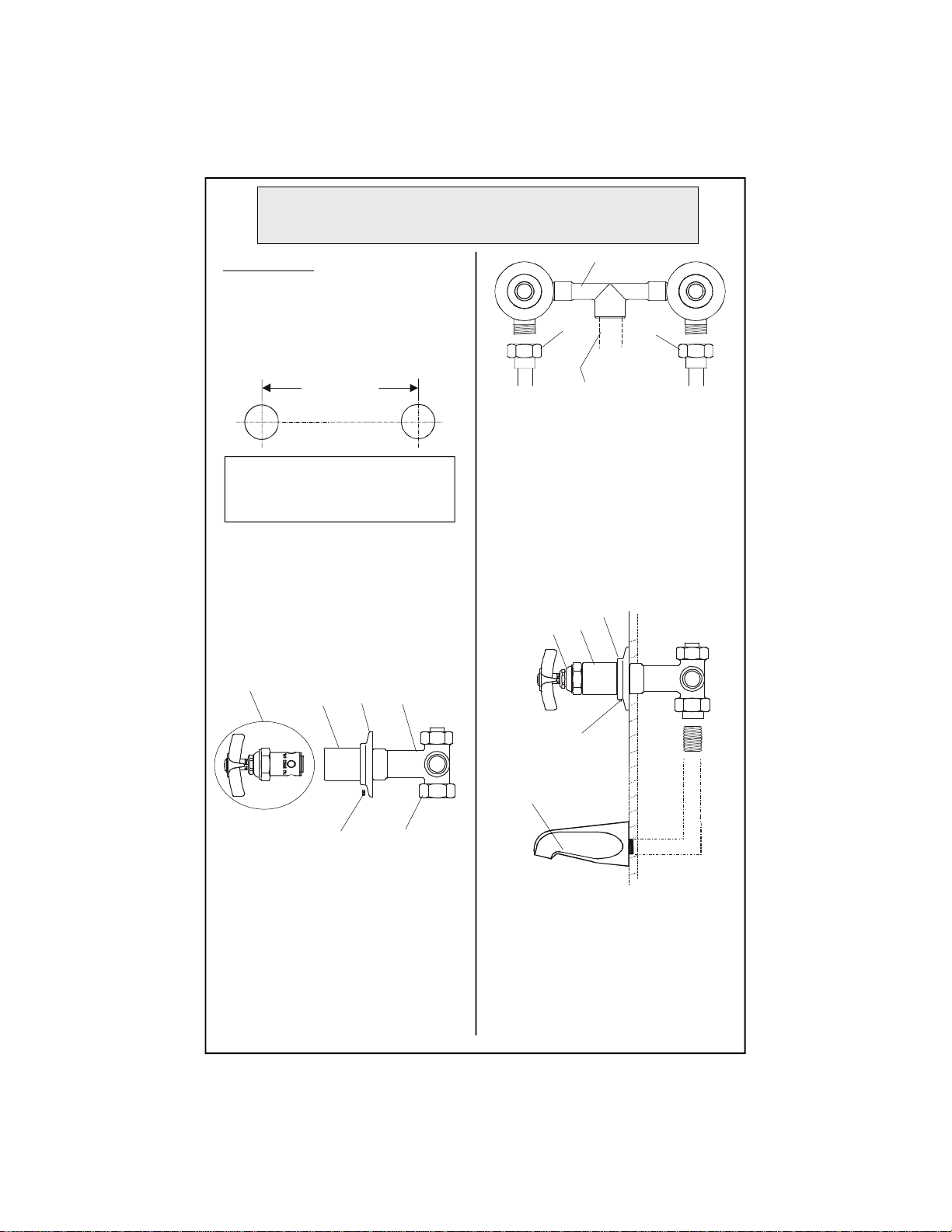
Instructions
Générales
L’Installation: La Vanne-
Caisse-Vide
1. Percer les trous9.5cm de centre-à-
centre où vous aller installer Nº.1.
Noter:Prier consulter les codes
plomberies applicables pour la
haulteur correcte de l’installation de
Nº.1au-dessous-de la sortie de Nº.13.
2.EnleverNº.3de Nº.1, installer Nº.3
sur la tuyauterie.
3. Réattacher Nº.1àNº.3,soyez
certain que Nº.2être à sa place et
resserrer avec une clef.
L’Installation: Du Robinet
4.Après on vider la bôite, enlever
Nº.6, N.7,N.8et Nº.9de Nº.5.
(Desserrer Nº.8à base de Nº.9, faire
glisser tous les deux de Nº.5.)
5.(Pour les modeles B-0695 et B-0696
ST, ajouter Nº.10 en utilisant Nº.11
pour joindre les raccords ensemble)
Faire les branchements à Nº.4:
B-0695: les arrivèes unions IPS (Iron Pipe
Size) de 1/2”; les raccords proches de 1/2”.
B-0696: les arrivèes unions de 5/8”; on
devoir souder les tuyaux cuivres aux
arrivèes.
B-0695 ST: utiliser les arrêts B-0416; le
tuyau NPT (National Pipe Thread) de 1/2”.
B-0696 ST: L’installeur devoir fournir le
joint de sordure de 5/8” à l’adapteur NPT
(National Pipe Thread) de 1/2” pour
attacher les tuyaux qui fournir l’eau à
Nº.10.1
la
sortie
l’arrivèe
2
3
le
mur
678
8
5
11
10
le mur
9
9
Utiliser Nº.10 et Nº.11 pour les modèles
B-0695 et B-0696 ST
l’arrivèe
fournir
tuyau
15
13
L’Installation: De L’Ajutage
6.Attacher Nº.12 sur le tuyau qui
fournir l’eau; visser Nº.15 dans
l’accessoire de Nº.13.
12
7. Marquer les trous sur le mur pour
attacherNº.16; utiliserle Nº.18 fourni
pour attacher Nº.16 au mur.
8.Insérer
Nº.17 dans
le trou de
Nº.16.
18
16
17
15
9. Recommencer l’eau et vérifier s’il
y a des fuites.
Voir le diagramme de la
circulation au page 8.

Allgemeine
Anleitungen
Installation: Vakuumunterbrecher
1.Löcher, dievon Mittezu Mitte9,5
cm entfernt sind, in die Wand bohren,
woNr. 1installiert werden soll.
Anmerkung: Für die richtige Höhe von
Nr. 1über dem Auslauf von Nr. 13 bitte
die zutreffenden Installateurvorschriften
nachsehen.
2.Nr. 3von Nr. 1entfernen,Nr. 3auf
dem Rohrsystem installieren.
3. Nr. 1wieder mit Nr. 3verbinden.
Sicherstellen, daß Nr.2richtig
eingesetzt ist, und mit einem
Schraubenschlüssel festziehen.
Installation: (Armaturrumpf)
4.Nach demAuspacken von Nr. 4, Nr.
6, 7, 8und9von Nr. 5entfernen.
(Nr. 8unten auf Nr. 9lösen, beide von
Nr. 5abziehen.
5.(Für dieModelleB-0695 STund
B-0696ST Nr.10 hinzufügenund Nr.
11 verwenden, um die Kupplungen
miteinander zu verbinden.
Herstellung der Verbindung mit Nr. 4:
B-0695: Einlaufrohr mit 1/2” IPS FE
Innenverschraubung;1/2” Verschlußnippel.
B-0696: 5/8” Einlaufrohre; Kupferrohre
müssen mit Einlaufrohren verschweißt
werden.
B-0695 ST: B-0416 Stopfen benutzen;
Rohre Größe 1/2” NPT. (National Pipe
Thread)
B-0696 ST: Der Installateur muß das 5/8”
Verbindungstück mit dem 1/2”NPT.
(National Pipe Thread) Zwischenstück
verschweißen, um die Zulaufrohre mit Nr.
10 zu verbinden.
1Ablauf
Einlauf
2
3
Wand
678
8
5
11
10
Wand
9
9
Nr.10 und Nr.11 für Modelle B-0695
ST und B-0696 ST benutzen.
Einlauf
Zulaufrohr
15
13
Schwenkhahninstallation
6. Nr. 12 mit dem Zulaufrohr verbinden;
Nr. 15 inNr. 13 einschrauben.
12
7. Löcher an der
Wand fürTeil 16
markieren;
mitgelieferteNr. 18
benutzen,um Nr. 16
an der Wand zu
befestigen.
8.Nr. 17 in das Loch
vonNr. 16 einfügen.
18
16
17
15
9. Wasserzufuhr andrehen und auf
Lecksprüfen.
Siehe Durchflußdiagram auf Seite 8.
T&S BRASS AND BRONZE WORKS, INC.
A firm commitment to application-engineered plumbing products
2 Saddleback Cove, P.O. Box 1088, T & S Brass-Europe
Travelers Rest, SC 29690 ‘De Veenhoeve’
Phone: (864) 834-4102 Oude Nieuwveenseweg 84
Fax: (864) 834-3518 2441 CW Nieuwveen
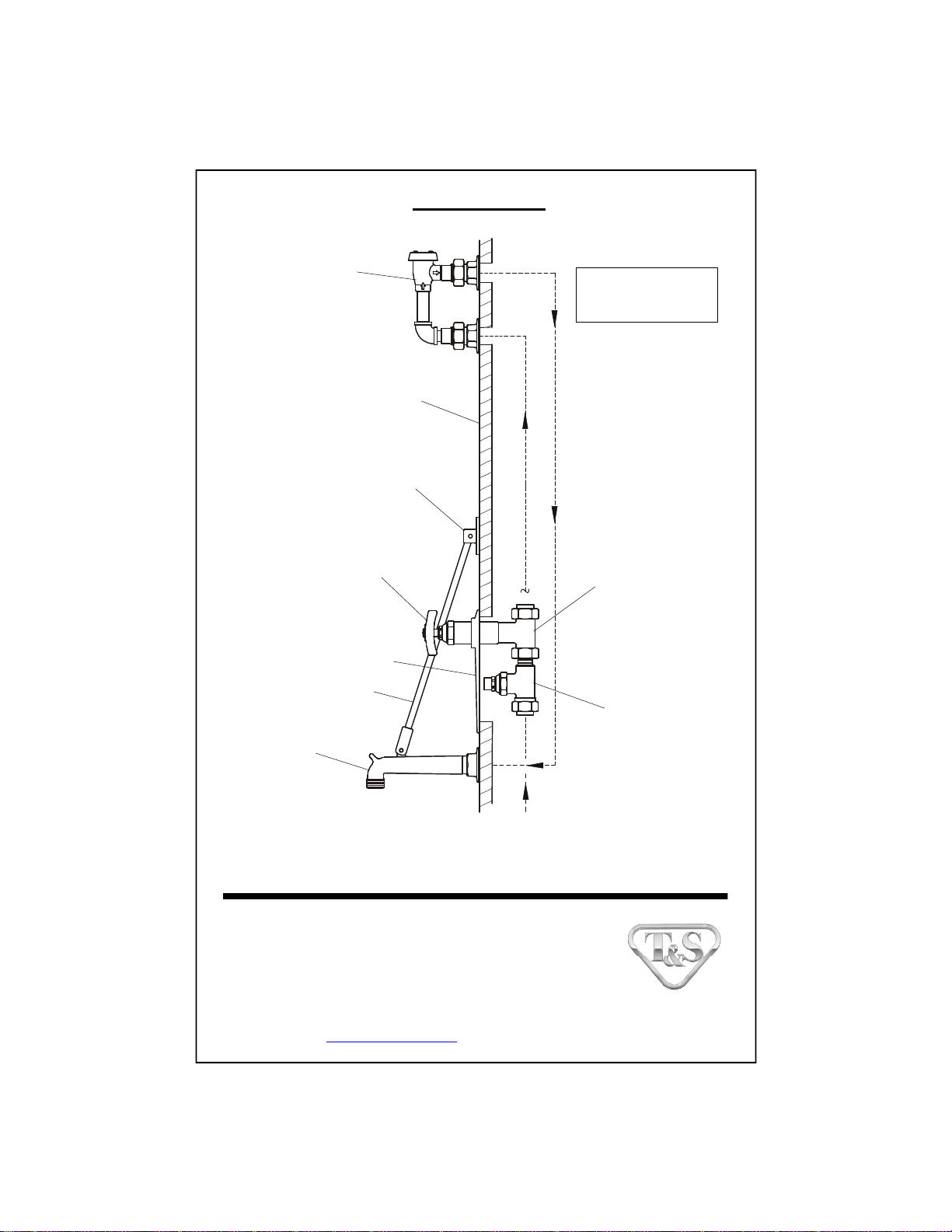
Flow diagram
Plumbingsupplied
byothers
B-0929A
Vacuum
Breaker
UpperNozzle
Support
Spindle
Assembly
Escutcheon
Support Rod
Spout
Concealed
By-Pass
MixingValve
B-0416
Stop
Wall
Water
Supply
Inlet
Installationand
Maintenance
Instructions
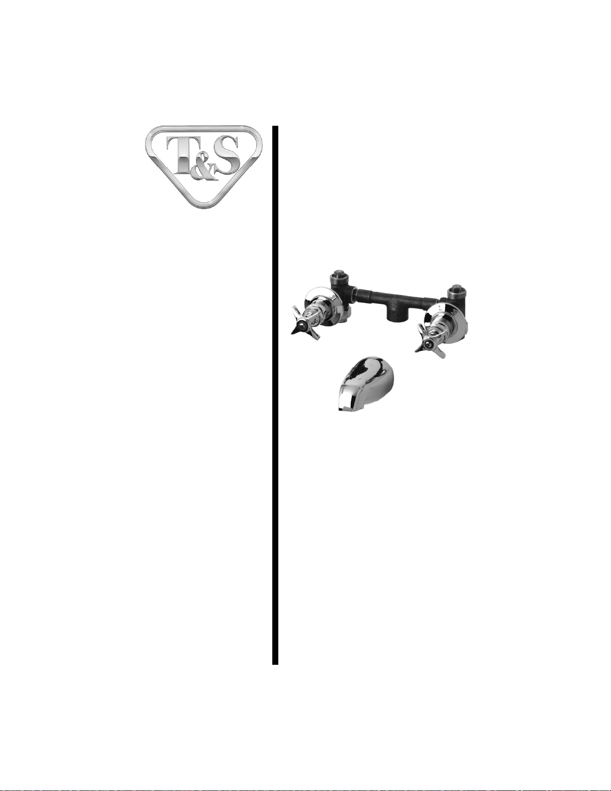
B-1070 Concealed
By-PassMixing Valve
Deutsch: Installations- und
Wartungsanleitungen
Español: la Instalación y las
Instruccionesde
Mantenimiento
Français: lesInstructions
d’Installation et
d’Entretien
Limited One Year Warranty
T&Swarrantstotheoriginalpurchaser(otherthan
forpurposesofresale)thatsuchproductisfreefrom
defectsinmaterialandworkmanshipforaperiodof
one(1)yearfromthedateofpurchase. Duringthis
one-yearwarrantyperiod, iftheproductis foundto
bedefective,T&S shall,at itsoptions, repairand/
orreplaceit. Toobtainwarrantyservice,products
mustbereturnedto...
T&SBrassandBronzeWorks,Inc.
Attn: WarrantyRepairDepartment
2SaddlebackCove
TravelersRest,SC 29690
Shipping,freight,insurance,andothertranspor-
tationchargesoftheproducttoT&Sandthereturn
ofrepairedorreplacedproducttothepurchaserare
theresponsibilityofthepurchaser. Repairand/or
replacementshallbemadewithinareasonabletime
afterreceiptbyT&Softhereturned product. This
warrantydoesnotcoverItemswhichhavereceived
secondaryfinishingorhavebeenalteredormodi-
fiedafterpurchase, orfordefectscausedbyphysi-
calabuseto ormisuseoftheproduct,orshipment
oftheproducts.
Anyexpresswarrantynotprovidedherein,and
anyremedyforBreachofContractwhichmightarise,
is hereby excluded and disclaimed. Any implied
warrantiesofmerchantabilityorfitnessforaparticu-
larpurposearelimitedtooneyearinduration. Under
no circumstances shall T&S be liable for loss of
useor anyspecialconsequentialcosts,expenses
ordamages.
Somestatesdonotallowlimitationsonhowlong
andimpliedwarrantylastsortheexclusionorlimi-
tationof incidentalorconsequentialdamages,so
theabovelimitationsorexclusionsmay not apply
toyou. Specificrightsunderthiswarrantyandother
rightsvaryfromstatetostate.
P/N: 098-006183-45 Rev.1
Date: 980805
Drawn: CW
Checked: MAB 10-16-98
Approved: MW 10-15-98
Exploded View
*Some items are listed for instructional purposes
and may not be sold as separate parts.
7
1
10 11
9
4
2
12
6
13
3
8
5

Part Number Guide
Mixing Valve Assembly
1Asm, Concealed By-Pass Mixing Valve B-1030
Body, Valve *
2Chamber Mix, 8" *
3Set Screw, Escutcheon Flange *
4Escutcheon *
5Escutcheon Tube *
6Asm, Spindle Eterna - Hot 005960-40
7Handle, 4-Arm Kitchen 002521-45
8Index Button, Blue - Cold 001660-45
Index Button, Red - Hot 001661-45
9Screw, Lever Handle 000922-45
10 Nut, Flange Coupling *
11 Union, 1/2 Female *
12 Plug, Solid 1/2" Square Head *
13 Spout, 1/2 NLT Bathtub *

General Instructions
Installation:
1. Shut off water supply and drain
lines. Drill (2) twoholes, approxi-
mately1-3/8” [34cm]diameter in wall
with 8” [20cm] center to center.
54
cartridge
assembly
3
1/2”
NPT
supply
line
4. Attach no.1onto no.10 and supply
pipes; tighten with a wrench.
5. Replace no.5, then no.4and make
sure no.4is flush against wall.
6. Replace no.6, attach no.7, no.8and
no.9.
10
7.Attach no.13 to outlet pipe using
Teflon Tape or pipe joint compound.
Make sure no.13 is flush against wall.
8. Turn on water and check for leaks.
2.After unpacking unit, remove
cartridge assembly from no.1.
(Loosen and remove no.3at base of
no.4, slide no.4off no.1.)
8” [20 cm]
Note: The unit is also available with
6” [15 cm] center to center inlets.
1
3. Remove no.10 from no.1and
attach to roughed-in piping (1/2” Iron
PipeSize female inlets)using Teflon
Tape or pipe joint compound.
1/2”
NPT
supply
line
3/4” IPS
supply
line to
tub
1
10 10
654
3
wall
13 3/4” IPS
supply
line to
tub
Instrucciones
Generales
Instalación:
1. Cierre la fuente de agua y desagüe
las tuberias. Perfore (2) dos huecos,
aproximadamentede1-3/8” [34 cm]de
díametro en la pared con distancia de
8” [20 cm] decentro a centro.
54
ensamble
de cartucho
3
1/2” NPT
tubería de
surtido
4. Junte la parte No.1a la parte No.10
y a la tubería de surtido; aprete con
unallave.
5. Coloque de nuevo la parte No.5,
luego la parte No.4y asegúrese que la
parte No.4este a rás con la pared.
6. Coloque de nuevo la parte No.6,
junte la partes No.7, No.8y No.9.
10
7. Junte la parte No.13 al tubo de
desagüe usando cinta de Teflon ó
compuesto de coyuntura. Asegúrese
que la parte No.13 este a rás con la
pared.
8. Abra el agua e inspeccione por
filtraciones.
2. Después de desempacar la unidad,
remuéva el ensamble de cartucho de la
parte No.1. (Afloje y remuéva la parte
No.3a la base de la parte No.4,
deslice la parte No.4de la parte No.1.
8” [20 cm]
Nota: Esta unidad también esta
disponible con entradas de 6” [15
cm]de centro a centro.
1
3. Remuéva la parte No.10 de la parte
No.1yjúnteloala tubería aproximada
(1/2”Tamaño DeTubería De Hierro
entradas femeninas) usando cintas de
Teflon ó compuesto de coyuntura.
1/2” NPT
tubería de
surtido
3/4” IPS
tubería de
surtido a la
bañera
1
10 10
654
3
pared
13
3/4” IPS
tubería de
surtido a
la bañera
Instructions
Générales
Installation:
1. Fermer la réserve de l’eau et
égoutter la tuyauterie. Percer deux (2)
trous avec un diamètre environ 34 cm.
avec 20cm. de centre à centre.
54
l’assemblage de
la cartouche
3
1/2”tuyau
qui fournir
l’eau NPT
4.AttacherNº. 1sur Nº.10etles
tuyaux qui fournir l’eau, resserrer avec
uneclef.
5. Remplacer Nº.5puis Nº.4etsoyez
certain que Nº.4être au même niveau
quelemur.
6.Remplacer Nº.6, attacher Nº.7, Nº.8
etNº.9.
10
7.Attacher Nº.13à la sortie en
utilisant le ruban en Téflon ou le
composé pour les tuyaux. Soyez
certain que Nº.13 être au même
niveau que le mur.
8. Recommencer l’eau et v érifier s’il y
a des fuites.
2.Après vous vider l’élément de la
bôite , enlever l’assemblage de la
cartouche de Nº.1. (Desserrer et
enlever Nº.3à la base de Nº.4, faire
glisser Nº.4de Nº.1).
8” [20 cm]
Noter: L’élément être disponible
aussi avec les arrivées 15cm. centre
àcentre.
1
3. Enlever Nº.10deNº.1etattacher à
la tuyauterie (des arrivées f éminines
des tuyaux en fer 1/2”)
en utilisant le ruban en Téflon ou le
composé pour les tuyaux.
1/2”tuyau
qui fournir
l’eau NPT
3/4” tuyau
qui fournir
l’eau à la
baignoire
1
10 10
654
3
le mur
13 3/4” tuyau
qui fournir
l’eau à la
baignoire
Allgemeine
Anleitungen
Installation:
1. Wasserzulauf absperren und
Leitungen entleeren. Zwei ungefähr
3,4cmgroße Löcher mit einem
Mittenabstand von 20cm in die Wand
bohren.
54
Patronengarnitur
3
1,25 cm
NPT-
Zuflußrohr
4. Nr. 1mit Nr. 10 undden
Zuflußrohren verbinden; mit
Schraubenschlüssel festziehen.
5.Nr. 5ersetzen und Nr. 4 ersetzen
und dann sicherstellen, daß Nr. 4glatt
an der Wand anliegt.
6. Nr. 6ersetzen, Nr. 7,Nr. 8und Nr. 9
befestigen.
10
7.Nr. 13 mitdemAusflußrohr unter
Verwendung von Teflonband und
Rohrdichtungsmasse verbinden.
Sicherstellen, daß Nr. 13glatt ander
Wandanliegt.
8. Wasserzulauf andrehen und auf
Dichtigkeitprüfen.
2. NachAuspacken der Einheit
Patronengarnitur Nr.1entfernen.
(Nr. 3vonNr. 4unten lösen und
entfernen,Nr. 4von Nr. 1
herunterschieben).
8” [20 cm]
Anmerkung: DieEinheitistauch
mit einem Mittenabstand der
Zuleitungenvon 15 cm erhältlich.
1
3.Nr. 10 von Nr. 1entfernen und mit
innenaufgerauhtem Rohr (1,25 cm
Eisenrohr mit Innengewinde) unter
Verwendung von Teflonband oder
Rohrdichtungsmasse verbinden.
1,25 cm
NPT-
Zuflußrohr
1,75 cm IPS-
Zuflußrohr
zur Wanne
1
10 10
654
3
wand
13 1,75 cm IPS-
Zuflußleitung
zur Wanne

T&S BRASS AND BRONZE WORKS, INC.
A firm commitment to application-engineered plumbing products
2 Saddleback Cove, P.O. Box 1088, T & S Brass-Europe
Travelers Rest, SC 29690 ‘De Veenhoeve’
Phone: (864) 834-4102 Oude Nieuwveenseweg 84
Fax: (864) 834-3518 2441 CW Nieuwveen
RELATEDT&SBRASSPRODUCTLINE
B-1030
Concealed By-
Pass Mixing
Valve
B-1065
Combination
Bath and
Shower Fitting
Installation and
Maintenance
Instructions
ATMOSPHERIC
VACUUM BREAKERS
B-0968 & B-0968-RK01 (3/8”)
B-0969 & B-0969-RK01 (1/2”)
Deutsch: Installations- und
Wartungsanleitungen
Español: la Instalación y las In-
strucciones de Man-
tenimiento
Français: les Instructions
d’Installation et
d’Entretien
Limited One Year Warranty
T&S warrants to the original purchaser (other
than for purposes of resale) that such product is
free from defects in material and workmanship
for a period of one (1) year from the date of
purchase. During this one-year warranty period,
if the product is found to be defective, T&S shall,
at its options, repair and/or replace it. To obtain
warranty service, products must be returned
to...
T&S Brass and Bronze Works, Inc.
Attn: Warranty Repair Department
2 Saddleback Cove
Travelers Rest, SC 29690
Shipping, freight, insurance, and other
transportation charges of the product to T&S
and the return of repaired or replaced product
to the purchaser are the responsibility of the
purchaser. Repair and/or replacement shall be
made within a reasonable time after receipt by
T&S of the returned product. This warranty does
not cover Items which have received secondary
finishing or have been altered or modified after
purchase, or for defects caused by physical
abuse to or misuse of the product, or shipment
of the products.
Any express warranty not provided herein, and
any remedy for Breach of Contract which might
arise, is hereby excluded and disclaimed. Any
implied warranties of merchantability or fitness
for a particular purpose are limited to one year in
duration. Under no circumstances shall T&S be
liable for loss of use or any special consequential
costs, expenses or damages.
Some states do not allow limitations on how
long and implied warranty lasts or the exclusion
or limitation of incidental or consequential dam-
ages, so the above limitations or exclusions may
not apply to you. Specific rights under this war-
ranty and other rights vary from state to state.
P/N: 098-009549-45 Rev.6
Date: 01-08-08
Drawn: TEH
Checked: GEF 01-08-08
Approved: JHB 01-08-08
Exploded View
B-0968 (3/8") B-0969 (1/2")
1/2" Vacuum Breaker
Repair Kit
B-0969-RK01
3/8" Vacuum Breaker
Repair Kit
B-0968-RK01
1
2
3
4
5
6
7
8
2
*Some items are listed for instructional purposes
and may not be sold as separate parts.

3
B-0968 Vacuum Breaker Assemblies & Kit
Screws
Nameplate
Coverplate
Insert
Large O-Ring
Small O-Ring
Piston
Body, Vacuum Breaker 3/8”
Part Number Guide
(*)
(*)
(*)
(*)
(*)
(*) Indicates those items that are included in the B-0968-RK01
Vacuum Breaker Repair Kit
1
2
3
4
5
6
7
8
*
*
*
*
*
*
*
*
B-0969 Vacuum Breaker Assemblies & Kit
Screws
Nameplate
Coverplate
Insert
O-Ring
Sealing Disk
Piston
Body, Vacuum Breaker 1/2”
(*)
(*)
(*)
(*)
(*)
(*) Indicates those items that are included in the B-0969-RK01
Vacuum Breaker Repair Kit
1
2
3
4
5
6
7
8
*
*
*
*
*
*
*
*

Typical Installation:
Single Vacuum Breaker
1. Vacuum breaker must be installed
with the supply connected to the bot-
tom and the outlet connected to the
appliance, as shown below:
2. The bottom of the no.8should be
at least 6” above the flood rim of the
fixture or appliance.
3. When using a portable appliance,
no.8should be installed at least 6”
above the highest point to which the
outlet can be raised, as shown:
Note: Where the device is a
separate unit, in the absence of a
Critical Installation Level (CIL)
mark, the extreme bottom of the
no.8 casting should be used to
determine its installed position.
Where the device is incorporated
in an outlet tube furnished by the
manufacturer, the extreme bot-
tom of the internal unit should
be noted on the outside of the
tube by a CIL line, for use in
determining its installed position.
4. The water supply valve must be
installed on the supply side (ahead)
of the vacuum breaker, and no shut-
off valve should be installed on the
outlet side (downstream).
5. The vacuum breaker should not be
subjected to continuous pressure for
more than twelve (12) hours.
Note: This device should not be
installed in a concealed or inac-
cessible location, nor where the
venting water from the device
during its normal functioning
may be deemed objectionable.
not less than 6”
(CIL)
supply
valve fixture or
appliance
overflow
or flood
rim
highest position of appliance not
less than 6” (CIL)
supply
valve
8
8
4
General Instructions
Table of contents
Other T&S Plumbing Product manuals

T&S
T&S B-0200-LN User manual

T&S
T&S B-1171 User manual

T&S
T&S B-0963 User manual

T&S
T&S B-0230 User manual

T&S
T&S B-1100 SERIES User manual

T&S
T&S B-1200 Series User manual

T&S
T&S B-0850 Series User manual

T&S
T&S EasyInstall B-2300 Series User manual

T&S
T&S B-0968 User manual

T&S
T&S Equip 5EF-1D-WG User manual


Popular Plumbing Product manuals by other brands

Toto
Toto Standard EcoPower TEL5GSC installation manual

JohnsonSuisse
JohnsonSuisse Emilia FTW Suite JTTE401 installation instructions

Moen
Moen Divine TS350BN Show House Replacement parts

MAINLINE
MAINLINE Prediction Elite Series Installation

Kohler
Kohler K-5805 Installation and care guide

RIHO
RIHO NAUTIC 3000 N111 manual


