T&S B-0102-A User manual
Installation and
Maintenance
Instructions
P/N: 098-005241-45 Rev 5
Date: 01-14-15
Drawn: TEH
Checked: JRM 01-26-15
Approved: JHB 01-26-15
Limited One Year Warranty
T&S warrants to the original purchaser
(other than for purposes of resale) that such
product is free from defects in material and
workmanship for a period of one (1) year
from the date of purchase. During this one-
year warranty period, if the product is found
to be defecve, T&S shall, at its opons,
repair and/or replace it. To obtain warranty
service, products must be returned to...
T&S Brass and Bronze Works, Inc.
AƩn: Warranty Repair Department
2 Saddleback Cove
Travelers Rest, SC 29690
Shipping, freight, insurance, and other
transportation charges of the product
to T&S and the return of repaired or
replaced product to the purchaser are the
responsibility of the purchaser. Repair
and/or replacement shall be made within a
reasonable me aer receipt by T&S of the
returned product. This warranty does not
cover Items which have received secondary
finishing or have been altered or modified
aer purchase, or for defects caused by
physical abuse to or misuse of the product,
or shipment of the products.
Any express warranty not provided
herein, and any remedy for Breach of
Contract which might arise, is hereby
excluded and disclaimed. Any implied
warranes of merchantability or fitness for
a parcular purpose are limited to one year
in duraon. Under no circumstances shall
T&S be liable for loss of use or any special
consequenal costs, expenses or damages.
Some states do not allow limitations
on how long and implied warranty lasts
or the exclusion or limitaon of incidental
or consequenal damages, so the above
limitaons or exclusions may not apply to
you. Specific rights under this warranty and
other rights vary from state to state.
BASE FAUCET
ASSEMBLY
Deutsch: InstallaƟons- und War-
tungsanleitungen
Español: la Instalación y las
Instrucciones de Man-
tenimiento
Français: les InstrucƟons d’Instal-
laƟon et d’EntreƟen
2
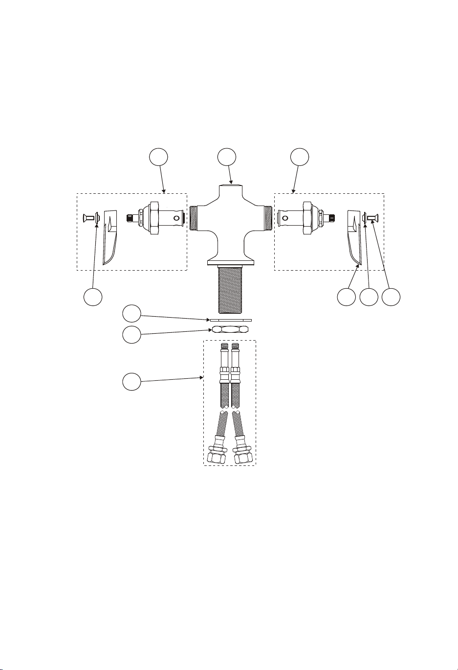
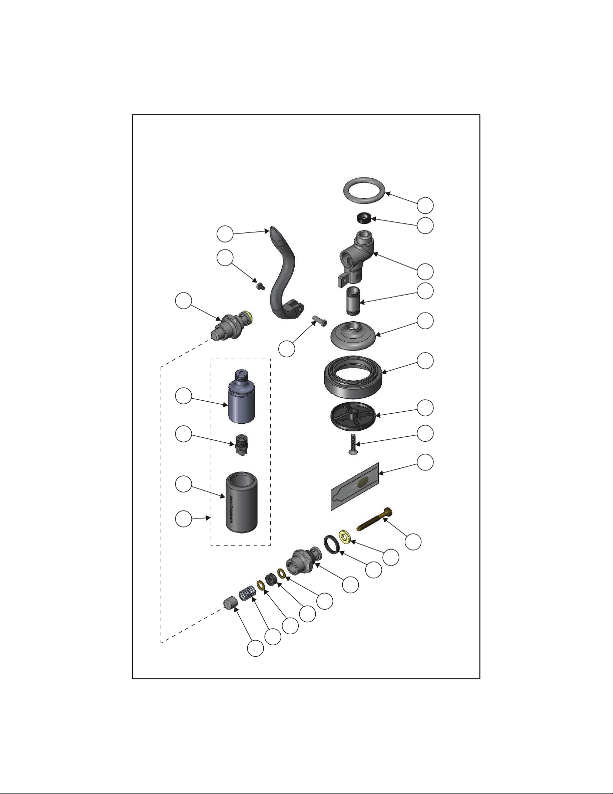
Exploded View
7
10 98
4
5
6
3 1 2

3
Part Number Guide
Base Faucet Assembly
1 Base Faucet N/A
2 Asm, Spindle LH - Eterna with Spring Checks 002711-40
Asm, Spindle LH - Eterna 002713-40
3 Asm, Spindle RH - Eterna with Spring Checks 002712-40
Asm, Spindle RH - Eterna 002714-40
4 Washer, Body 002290-45
5 Locknut, Shank 000965-45
6 Flexible Connector Hoses 012534-45
7 Lever Handle (Blank) 001638-45
8 Screw, Lever Handle 000922-45
9 Index, Buon - Blue 001660-45
10 Index, Buon - Red 001661-45
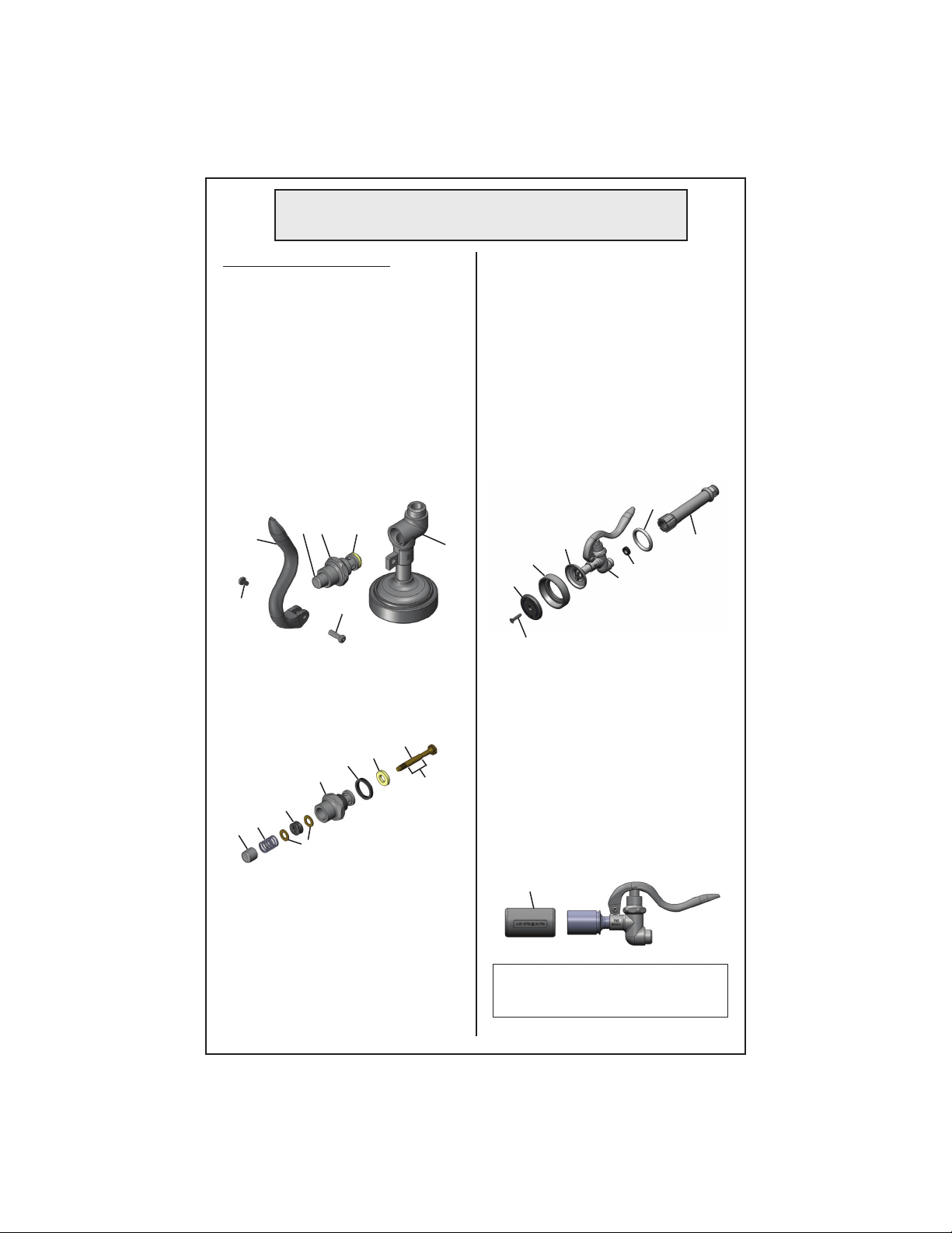
4
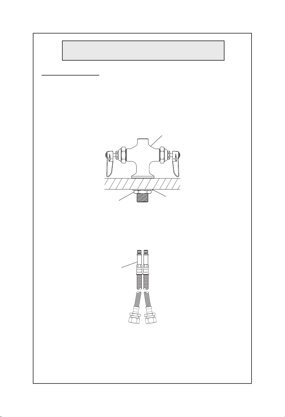
Faucet InstallaƟon:
1. Shut offwater supply and drain lines. Drill a hole approximately
1-1/2” diameter in countertop where you are installing no.1.
2. Remove no.5and no.4from no.1.
3. Place no.1through hole in sink, align hot and cold sides parallel to sink
line.
sink
54
4. Install no.4and no.5on no.1, ghten no.5.
5. Install no.6into threaded holes of no.5. Tighten by hand.
6. Connect supply lines and check for leaks.
1
General Instructions
6

5
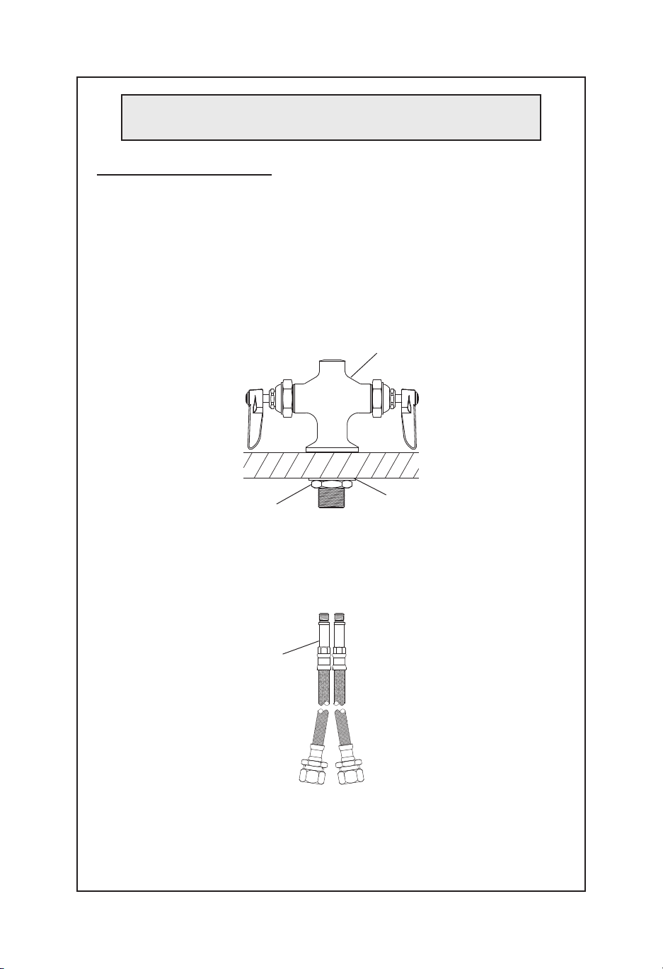
Lavatorio
Instrucciones Generales
Instalación de la canilla:
1. Cierre el suministro de agua y líneas de drenaje. Perfore un agujero de
aproximadamente 3,81 cm de diámetro en el mostrador donde va a
instalar el no. 1.
2. Remueva el no. 5y el no. 4del no. 1.
3. Coloque el no. 1entre al agujero en el fregadero, alinee los lados
calientes y fríos paralelo a la linea del fregadero.
54
4. Instale el no. 4y el no. 5 en el no. 1; cierre el no. 5.
5. Instale el no. 6entre los agujeros roscados del no. 5. Apriete por mano.
6. Conecte las lineas de suministro y revisa por fugas.
1
6

6
Tuyau du Robinet
Instructions Générales
InstallaƟon du Robinet:
1. Fermez l’arrivée d’eau et vidanger les tuyauteries. Percez un trou
d’environ 3,81 cm de diamètre dans le comptoir où vous installez le No.
1.
2. Rerez le No.5. et No.4. du No.1.
3. Placez le No.1. dans le trou de l’évier, alignez les cotés chauds et froids
parallèles à la ligne de l’évier.
54
4. Installez le No.4. et No.5. sur No.1., serrez le No.5.
5. Installez le No.6. dans les trous filetés du No. 5. Serrez à la main.
6. Raccordez les conduites d’alimentaon et vérifiez qu’il n’y ai aucune
fuite.
1
6
7
Waschbecken
Allgemeine Anleitungen
Wasserhahn InstallaƟon:
1. Wasserzufuhr ausschalten und Rohre entleeren. An der Stelle in der
Arbeitsfläche, wo Nr. 1installiert werden soll, wird eine Öffnung mit
einem Durchmesser von 3,81 cm gebohrt.
2. Nr. 5und Nr. 4von Nr. 1enernen.
3. Nr. 1durch die Öffnung im Becken einführen und Heiß- und
Kaltwasserleitungen parallel zur Beckenleitung ausrichten.
54
4. Nr. 4und Nr. 5an Nr. 1installieren. Nr. 5festziehen.
5. Nr. 6in den Gewindeöffnungen von Nr. 5installieren. Von Hand
festziehen.
6. Wasserleitungen erneut anschließen und auf undichte Stellen prüfen.
1
6

T&S BRASS AND BRONZE WORKS, INC.
A firm commitment to application-engineered plumbing products
2 Saddleback Cove, P.O. Box 1088, T & S Brass-Europe
Travelers Rest, SC 29690 ‘De Veenhoeve’
Phone: (864) 834-4102 Oude Nieuwveenseweg 84
Fax: (864) 834-3518 2441 CW Nieuwveen
B-0220-LN
Deck Mixing
Faucet
B-20K
Parts Kit
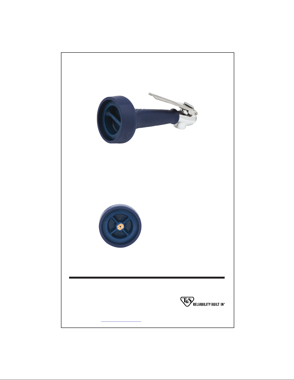
RELATED T&S BRASS PRODUCT LINE

Pre-Rinse Spray Valve
Limited One Year Warranty
T&S warrants to the original purchaser (other
than for purposes of resale) that such product
is free from defects in material and workman-
ship for a period of one (1) year from the date
of purchase. During this one-year warranty
period, if the product is found to be defective,
T&S shall, at its options, repair and/or replace
it. To obtain warranty service, products must
be returned to…
T&S Brass and Bronze Works, Inc.
Attn: Warranty Repair Department
2 Saddleback Cove
Travelers Rest, SC 29690
Shipping, freight, insurance, and other
transportation charges of the product to T&S
and the return of repaired or replaced product
to the purchaser are the responsibility of the
purchaser. Repair and/or replacement shall be
made within a reasonable time after receipt by
T&S of the returned product. This warranty does
not cover Items which have received secondary
finishing or have been altered or modified after
purchase, or for defects caused by physical
abuse to or misuse of the product, or shipment
of the products.
Any express warranty not provided herein,
and any remedy for Breach of Contract which
might arise, is hereby excluded and disclaimed.
Any implied warranties of merchantability or
fitness for a particular purpose are limited to
one year in duration. Under no circumstances
shall T&S be liable for loss of use or any special
consequential costs, expenses or damages.
Some states do not allow limitations on
how long and implied warranty lasts or the
exclusion or limitation of incidental or conse-
quential damages, so the above limitations or
exclusions may not apply to you. Specific rights
under this warranty and other rights vary from
state to state.
P/N: 098-011027-45 Rev.9
Date: 03-22-12
Drawn: TEH
Checked: JRM 03-26-12
Approved: JHB 03-27-12
Installation and
Maintenance
Instructions
B-0107
B-0107-C
B-0107-J
B-10K
B-10K-C
B-10K-J
UK-0107
UK-10K
EB-0107
EB-0107-C
EB-0107-J
EB-10K
EB-10K-C
EB-10K-J
2
Exploded View
1
2
3
7
8
9
10
11
21
13
14
15
16
17
18
17
19
20
12
25
24
23
5
6
4
22

3
Grey
Grey Part Number Guide
PARTS FOR ANY GREY T&S SPRAY VALVE
1
2
3
4
5
6
Ring, Hold Down
#27 Washer
Body, Spray Valve
Grey Handle
Nut, Handle
Screw, Handle
000907-45
010476-45
000065-40
001120-45
003198-45
003199-45
7
8
9
10
11
22
23
24
22
23
24
25
B-0107 (1.42 GPM)
Nipple
Cup, Spray
Ring, Sprayhead
1.42 GPM Sprayface
Screw, Sprayface
B-0107-C (0.65 GPM)
Assembly, B-0107C Spray Nozzle
0.65 GPM Grey Shield (No Outline Around Lettering)
0.65 GPM Spray Nozzle (0.65 Stamped on Face)
B-0107-J (1.07 GPM)
Assembly, B-0107-J Spray Nozzle
1.07 GPM Grey Shield (Square Outline)
1.07 GPM Spray Nozzle (1.07 Stamped on Face)
Nozzle Holder
000694-40
000019-40
007861-45
001121-45
000913-45
002662-40
002659-45
N/A
N/A
018292-45
N/A
N/A
Bonnet Assembly
Stem
Washer, Seat
Washer, Bonnet Binding
Bonnet
Washer, Bonnet Brass
Stem, Packing
Spring, Bonnet
Push Button
Grease Pack
002856-40
009306-20
012915-45
001040-45
000608-25
000974-45
001100-45
000895-45
000753-25
012665-45
12
13
14
15
16
17
18
19
20
21
1,2,3
PARTS
KIT
1,2,3
1,2,3
1,2,3
1,2,3
1,2,3
1,2,3
1,2,3
PARTS FOR ANY GREY BONNET ASSEMBLY
GREY SPRAY VALVES
1
1
1
2
3
#1 Parts included in B-10K
#2 Parts included in B-10K-C
#3 Parts included in B-10K-J

4
Blue
Blue Part Number Guide
PARTS FOR ANY BLUE T&S SPRAY VALVE
1
2
3
4
5
6
Ring, Hold Down
#27 Washer
Body, Spray Valve
Blue Handle
Nut, Handle
Screw, Handle
000907-45
010476-45
000065-40
011454-45
003198-45
003199-45
7
8
9
11
10
10
22
23
24
22
23
24
25
EB-0107 & UK-0107 Only
Nipple
Cup, Spray
Ring, Sprayhead
Screw, Sprayface
EB-0107 (4-6 GPM)
4-6 GPM Sprayface (No Wording on Face)
UK-0107 (1.42 GPM)
1.42 GPM Sprayface (Flow Rate on Face)
EB-0107-C (0.65 GPM)
Assembly, EB-0107C Spray Nozzle
0.65 GPM Blue Shield (No Outline Around Lettering)
0.65 GPM Spray Nozzle (0.65 Stamped on Face)
EB-0107-J (1.07 GPM)
Assembly, EB-0107-J Spray Nozzle
1.07 GPM Blue Shield (Square Outline)
1.07 GPM Spray Nozzle (1.07 Stamped on Face)
Nozzle Holder
000694-40
000019-40
011475-45
000913-45
011456-45
017288-45
N/A
011499-45
N/A
N/A
018293-45
N/A
N/A
Bonnet Assembly
Stem
Washer, Seat
Washer, Bonnet Binding
Bonnet
Washer, Bonnet Brass
Quad Seal
Spring, Bonnet
Push Button
Grease Pack
010594-40
009306-20
010563-45
010565-45
000608-25
000974-45
014615-45
000895-45
000753-25
010573-45
12
13
14
15
16
17
18
19
20
21
4,5,6,7
PARTS
KIT
4,5,6,7
4,5,6,7
4,5,6,7
4,5,6,7
4,5,6,7
4,5,6,7
4,5,6,7
PARTS FOR ANY BLUE BONNET ASSEMBLY
BLUE SPRAY VALVES
4,7
4,7
4
7
5
6
#4 Parts included in EB-10K
#5 Parts included in EB-10K-C
#6 Parts included in EB-10K-J
#7 Parts included in UK-10K
To replace worn parts:
1. Shut o water supply and drain
lines. For ease of disassembly and
reassembly, the handle grip can be
removed from no.3.
2. Unscrew no.5and no.6to remove
no.4. Unscrew and remove no.16
from no.3.
3. Hold no.20 with pliers in one
hand, and with screwdriver, carefully
unscrew no.13 from no.16.
4. Apply no.21 over smooth portion
of no.13. Replace no.14, no.15, no.17,
no.18 & no.19 with new parts. Dab
no.21 onto valve side of no.19 before
replacing.
3
8. For EB-0107/UK-0107 & B-0107
ONLY: To replace no.9, unscrew
no.11 and disassemble. Make sure
the groove side of no.9ts over
no.8, and no.10 rest on ridge side.
See Figure A.
9. To replace no.2, unscrew handle
grip from no.3and replace with new
no.2.
10. Reassemble; turn on water check
for leaks.
General Instructions
5
1620
5
6
4
16
14
13
18
19
20
17
15
5. Reassemble no.16 by inserting
no.13 through all parts. Hold no.20
with pliers, and carefully screw no.13
into no.20 until screw feels tight. Do
not use excessive force.
6. Reinsert no.16 in no.3and tighten
securely.
7. Reassemble no.4, no.5and no.6
on no.3.
11. For EB-0107-C, EB-0107-J,
B-0107-C & B-0107-J ONLY: To
replace no.23, slide no.23 o no.25,
and slide a new no.23 back onto
no.25. No.23 will snap into groove
on no.25. See Figure B.
* Verify the ow rate on no.23
matches spray tip inside no.25.
Caution: Turn o water supply at
base faucet when not in use.
Figure A
Figure B
11
10
9
8
1
3
23
13
apply no.21
here
2
handle
grip
T&S BRASS AND BRONZE WORKS, INC.
A firm commitment to application-engineered plumbing products
2 Saddleback Cove, P.O. Box 1088, T & S Brass-Europe
Travelers Rest, SC 29690 ‘De Veenhoeve’
Phone: (864) 834-4102 Oude Nieuwveenseweg 84
Fax: (864) 834-3518 2441 CW Nieuwveen
B-0108
JeTSpray
Spray Valve
RELATED T&S BRASS PRODUCT LINE
B-0108-C
JeTSpray
Low Flow
Spray Valve
Installationand
Maintenance
Instructions
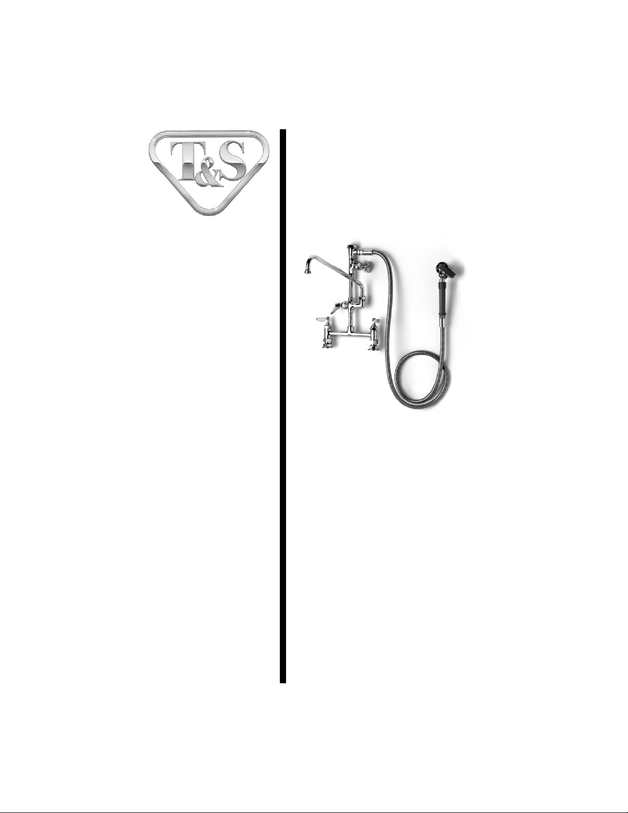
FAUCET WITH
NOZZLE AND SPRAY
HOSE ASSEMBLY
B-0177
Deutsch: Installations-und
Wartungsanleitungen
Español: la Instalación y las
Instruccionesde
Mantenimiento
Français: lesInstructions
d’Installation et
d’Entretien
Limited One Year Warranty
T&Swarrantstotheoriginalpurchaser(otherthan
forpurposesofresale)thatsuchproductisfreefrom
defectsinmaterialandworkmanshipforaperiodof
one(1)yearfromthedateofpurchase. Duringthis
one-yearwarrantyperiod,iftheproduct isfoundto
bedefective,T&S shall,at itsoptions, repair and/
orreplaceit. Toobtainwarrantyservice,products
mustbereturnedto...
T&SBrassandBronzeWorks,Inc.
Attn: WarrantyRepairDepartment
2SaddlebackCove
TravelersRest,SC 29690
Shipping,freight,insurance,andothertranspor-
tationchargesoftheproducttoT&Sandthereturn
ofrepairedorreplacedproducttothepurchaserare
theresponsibilityofthepurchaser. Repairand/or
replacementshallbemadewithinareasonabletime
afterreceiptbyT&Sof thereturned product. This
warrantydoesnotcoverItemswhichhavereceived
secondaryfinishingorhavebeenalteredormodi-
fiedafterpurchase, orfordefectscaused byphysi-
calabusetoormisuseoftheproduct,orshipment
oftheproducts.
Anyexpresswarrantynotprovidedherein,and
anyremedyforBreachofContractwhichmightarise,
is hereby excluded and disclaimed. Any implied
warrantiesofmerchantabilityorfitnessforaparticu-
larpurposearelimitedtooneyearinduration. Under
no circumstances shall T&S be liable for loss of
useor anyspecialconsequentialcosts,expenses
ordamages.
Somestatesdonotallowlimitationsonhowlong
andimpliedwarrantylastsortheexclusionorlimi-
tationof incidentalorconsequentialdamages,so
theabovelimitationsorexclusionsmay not apply
toyou. Specificrightsunderthiswarrantyandother
rightsvaryfromstatetostate.
P/N: 098-012448-45 Rev.0
Date: 990714
Drawn: CW
Checked: MAB11-12-99
Approved: MVW11-13-99

Exploded View
* Some items are listed for instructional purposes and may not be sold as separate parts.
6
7
8
10
9
11
15
16
17
18
19
20
21
25
22
26
29
32
33
31
27
28
30
23
24
8
12
13
8
14
3
4
1
2
5
2

Part Number Guide
3
Faucet Assembly
1
Asm, Faucet (Rigid)
002829-40
2
Faucet Body (Rigid)
*
3
Asm, Coupling Flange
002893-40
4
Washer
001019-45
5
Asm, Cartridge
LH, w/Spring Checks
002711-40
RH, w/Spring Checks
002712-40
6
Handle, Lever - Hot
001637-45
Handle, Lever - Cold
001636-45
7
Index, Button
Hot (Red)
001661-45
Cold (Blue)
001660-45
8
Screw, Handle
000922-45
21
Nipple, 3/8" X 4"
*
22
Valve Body
*
23
Asm, Cartridge (Cold)
005959-40
24
Handle, 4-Arm
002521-45
25
Grease Tube
*
26
Nipple
002535-25
27 Asm, Vacuum Breaker 3/8" B-0968
28
Adapter, 3/8" MA
000545-25
29
Washer #27
010476-45
30
Asm, Flex S/S Hose
B-0080-H
31
Asm, Spray Head
005969-40
32
Asm, Wall Hook
B-0104-D
33
Screws, Wall Mount
000915-45
Add-On Faucet Assembly
9
Asm, Add-on Faucet
B-0155, B-0156, B-0157
005964-40
10
Nipple, 3/8" X 3"
000358-40
11
Faucet Body
*
12
Asm, Cartridge, Quarter Turn
007947-40
13
Handle, Lever (Blank)
001638-45
8
Screw, Handle
000922-45

Part Number Guide - con’t
4
***Repair kit includes items #16 and #17.
Nozzle Assembly
14
Asm, Nozzle Swing
Nozzle, 6”
059X
Nozzle, 12”
062X
Nozzle, 18”
065X
15
Repair Kit***
011643-45
16
"O"-Ring
*
17
Sleeve, Swivel
*
18
Swivel Piece
*
19
Washer, Swivel Piece
*
20
Nut, Swivel
*

5
General Instructions
Faucet Installation:
1. Drill (2) two holes, approximately
1-1/4” diameter in countertop with 8”
centers, where you are installing
no.2.
2. Apply Teflon tape or pipe joint
compound to water supply lines.
3.Connect no.2to water supply lines
by screwing no.3(with eccentric
centers) onto nipple (supplied by
others) and tightening no.3against
countertop. (Nut under countertop
to be supplied by others). Trim
supply lines if necessary.
water supply line
countertop
nut
(supplied by others)
8”[20 cm]
3
2
Nozzle Installation:
Note: Nozzles should be installed
first. See diagram below:
Ifinstalling to an existing rigid pre-
rinseunit orbase faucet
1. Shut off water supply and drain
lines. Remove no.21fromno.2.
Apply Teflon tape or pipe joint
compound to threaded ends of
no.10.
2. Place no.10 into no.2and tighten
firmlybyhand.
To Install Swing Nozzle:
1. Insert no.14 into no.11 and rotate
to desired position at sink.
Note: See Repair Kit 011643-45 for
replacement of no.16 and no.17.
2. Tighten no.20 firmly with a wrench.
14
10
20
11
Enlarged View
16
17
18
21
2

General Instructions
1. Apply Teflon tape on threaded ends of no.21.
Place no.21 into no.22, tighten by hand. Apply
loctite on no.26, insert between no.22 and no.27,
tighten no.27 with a wrench.
2. Apply Teflon tape or pipe joint compound to no.21
and place into no.11 and tighten by hand.
1. Apply Teflon tape on no.28 and place onto no.27.
2. Apply Teflon tape to threaded end of no.28. Attach
no.30 to no.28 (make sure no.29 is in place).
3. Turn on water supply and check for leaks.
4. Install no.32 in a convient location.
26
22
21
6
Installation of Control Valve:
Vacuum Breaker and Hose Installation:
27 28 29
30
11
This manual suits for next models
1
Table of contents
Languages:
Other T&S Plumbing Product manuals


Popular Plumbing Product manuals by other brands

Santec
Santec TH-8010 Installation instruction

Heritage Bathrooms
Heritage Bathrooms AWG101S Fitting Instructions & Contents List

Delabie
Delabie TEMPOSOFT 742000 manual

Hans Grohe
Hans Grohe Showerpipe 240 1jet P 27633000 Instructions for use/assembly instructions

Brizo
Brizo Loki Series manual

Sunlighten
Sunlighten Signature Power Box owner's manual


