tau BIUNO User manual

1
BIUNO
Automazione per porte snodate
Automations for articulated doors
Automatisierung für Falttore
Automatisations pour portes à bras articulé
Sistema de automatizacion para verjas articulada
Via Enrico Fermi, 43 - 36066 Sandrigo (VI) Italia
Tel +39 0444 750190 - Fax +39 0444 750376 - info@tauitalia.com - www.tauitalia.com
D-MNL0BIUNO 25-09-2020 - Rev.07
IT - Istruzioni originali

2

3
BIUNO BIUNO-BT BIUNO-BTR
Alimentazione / Power / Stromspeisung / Alimentation / Alimentación 230V AC
Frequenza / Frequency / Frequenz / Fréquence / Frequencia 50/60 Hz -
Condensatore / Capacitor / Kodensator / Condensateur / Condensador 12,5 µf -
Motore / Motor / Motor / Moteur / Motor 230V AC 18V DC 24V DC
Tempo di apertura 90° / Opening time 90° / Laufzeit, 90°
Temps de ouverture 90° / Tiempo de apertura 90° 19 sec. 16 sec. 11 sec.
Assorbimento / Absorption / Stromentnahme / Absorption / Absorción 1 A
Potenza assorbita / Absorbed rated power / Aufgenommene Leistung
Puissance absorbée / Potencia nominal absorbida 140 W 16 W 16 W
Rapporto di riduzione / Reduction ratio / Übersetzungsverhältnis
Rapport de réduction / Relación de reducción 1/672
Intervento di termoprotezione / Thermal protection trips at / Eingreifen des Warmeschutzes /
Intervention protection thermique / Interventiòn termoprotecciòn 150°C -
Grado di protezione / Protection level / Schutzart
Degré de protection / Grado de protección IP 40
Ciclo di lavoro / Working cicle / Arbeitzyklus / Cycle de travail / Ciclo de trabajo 50% 100%
Temperatura di esercizio / Operating temperature / Betriebstemperatur
Température de fonctionnement / Température de fonctionnement -20°C + 55°C
Coppia max / Max torque / Max Motordrehmoment / Couple max / Par màx 350 Nm 395 Nm
Portone a libro: lunghezza max. semi anta / Folding door: max. length of half-leaf / Falttoren: max.
halb Torügellänge / Porte à livre: longueur max. demi-battant / Puertas de libro: longitud max.
media-hoja
1,2 m (650BTB1) or 1,5 m (650BTB1L)
Portone a libro: peso max. semi-anta /Folding door: max. half-leaf weight / Falttoren : peso max.
semi-anta / Porte à livre: poids max demi-battant / Puertas de libro: peso máximo de la media-hoja 200 Kg 200 Kg 150 Kg
Peso / Weight / Gewicht / Poids / Peso 9 Kg 8,5 Kg
Portone a battente: lunghezza anta singola / Hinged door: single leaf length / Drehtor: Einblattlänge /
Porte à battant: longeur vantail simple / Puerta batiente: longitud hoja individual 2 m (650BRCEB1)
Portone a battente: peso max anta singola / Hinged door: max single leaf weight / Drehtor:
max. Einzelblattgewicht / Porte à battant poids maximal vantail simple / Puerta batiente: peso
máximo hoja individual
300 Kg 300 Kg 150 Kg
Quando il sistema in 12V DC è alimentato unicamente dalla batteria (in caso di black-out oppure in abbinamento con pannello
fotovoltaico), le prestazioni espresse dal motoriduttore (forza e velocità) si riducono del 30% ca.
When the system is in the 12V DC mode and is powered by the battery only (in the event of a power failure or when used in con-
junction with a photovoltaic panel), the gear motor’s output (power and speed) is reduced by approximately 30%.
Anmerkung: wenn das 12V DC System nur über Batterie gespeist ist (bei Stromausfall oder in Kombination mit einem Photovol-
taicpaneel), verringern sich die leistungen des Getriebemotors (Kraft und Geschwindigkeit) um ca. 30%.
Attention : quand le système à 12V CC est alimenté uniquement par la batterie (en cas de coupure de courant ou bien en associa-
tion avec un panneau photovoltaïque), les performances du motoréducteur (force et vitesse) diminuent d’environ 30% .
Nota: cuando el sistema de 12V DC es alimentado únicamente por la batería (en caso de corte de corriente, o bien
combinado con panel fotovoltaico), las prestaciones del motorreductor (fuerza y velocidad) se reducen en un 30%.
Le automazioni della serie BIUNO e BIUNO-BT sono state progettate per movimentare porte snodate o a battente per uso industriale. SI FA
ESPRESSO DIVIETO DI UTILIZZARE L’APPARECCHIO PER SCOPI DIVERSI O IN CIRCOSTANZE DIVERSE DA QUELLE MENZIONATE.
The automations of the BIUNO and BIUNO-BT series have been designed to handle articulated or swing doors for industrial use. THE USE OF THE
EQUIPMENT FOR PURPOSES OR CIRCUMSTANCES OTHER THAN THOSE MENTIONED IS STRICTLY PROHIBITED.
Die Automationen der Serien BIUNO und BIUNO-BT sind für den Einsatz mit Gelenk- oder Schwenktüren für den industriellen Einsatz konzipiert.
ES IST AUSDRÜCKLICH VERBOTEN, DAS GERÄT FÜR ANDERE ZWECKE ODER ANDERE BEDINGUNGEN ALS ERWÄHNT ZU BENUTZEN.
Les automatismes BIUNO et BIUNO-BT ont été conçus pour les portes articulées ou à battants à usage industriel. IL EST STRICTEMENT INTERDIT
D’UTILISER L’APPAREIL DANS DES BUTS OU DES CONTEXTES DIFFÉRENTS DE CEUX QUI SONT INDIQUÉS.
Los automatismos de la serie BIUNO y BIUNO-BT han sido diseñados para desplazar puertas articuladas o batientes para uso industrial. QUEDA
TERMINANTEMENTE PROHIBIDO UTILIZAR EL APARATO PARA FINES DISTINTOS O EN CIRCUNSTANCIAS DISTINTAS DE LAS QUE SE
CITAN.
BIUNO Series
Descrizione e
caratteristiche
Description
and
characteristics
Baschreibung
und Merkmale
Description et
caractéristiques
Descripción y
características

4
DICHIARAZIONE DI INCORPORAZIONE DEL COSTRUTTORE
(ai sensi della Direttiva Europea 2006/42/CE AlI. II.B)
Fabbricante: TAU S.r.l.
Indirizzo: Via E. Fermi, 43
36066 Sandrigo (Vi)
ITALIA
Dichiara sotto la propria responsabilità che il prodotto: Attuatore elettromeccanico
realizzato per il movimento automatico di: Portoni Uso Industriale
per uso in ambiente: Industriale
completo di: -
Modello: BIUNO
Tipo: BIUNO / BIUNO-BT / BIUNO-BTR
Numero di serie: VEDI ETICHETTA ARGENTATA
Denominazione commerciale: AUTOMAZIONE PER PORTONI USO INDUSTRIALE
È realizzato per essere incorporato su una chiusura (portone uso industriale) o per essere assemblato con altri dispositivi al ne
di movimentare una tale chiusura per costituire una macchine ai sensi della Direttiva Macchine 2006/42/CE.
Dichiara inoltre che questo prodotto è conforme ai requisiti essenziali di sicurezza delle seguenti ulteriori direttive CEE:
- 2014/35/EU Direttiva Bassa Tensione
- 2014/30/EU Direttiva Compatibilità Elettromagnetica
ed, ove richiesto, alla Direttiva:
- 2014/53/EU Apparecchiature Radio e apparecchiature terminali di telecomunicazione
Dichiara inoltre che non è consentito mettere in servizio il macchinario no a che la macchina in cui sarà incorporato o di
cui diverrà componente sia stata identicata e ne sia stata dichiarata la conformità alle condizioni della Direttiva 2006/42/CE.
Sono applicate le seguenti norme e speciche tecniche:
EN 61000-6-2; EN 61000-6-3; EN 60335-1; EN 300 220-2 V2.4.1; EN 12453:2000; EN 12445:2000;
EN 60335-2-103
Si impegna a trasmettere, su richiesta adeguatamente motivata delle autorità nazionali, informazioni pertinenti sulle
quasi-macchine.
Sandrigo, 07/03/2018
Il Rappresentante Legale
_____________________________________
Loris Virgilio Danieli
Nome e indirizzo della persona autorizzata a costituire la documentazione tecnica pertinente:
Loris Virgilio Danieli - via E. Fermi, 43 - 36066 Sandrigo (Vi) Italia
BIUNO Series
ITALIANO

5
AVVERTENZE PER L’INSTALLATORE
OBBLIGHI GENERALI PER LA SICUREZZA
1) Leggere attentamente le istruzioni prima di procedere all’in-
stallazione, in quanto forniscono importanti indicazioni con-
cernenti la sicurezza, l’installazione, l’uso e la manutenzione.
Una errata installazione o un errato uso del prodotto può por-
tare a gravi danni alle persone.
2) I materiali dell’imballaggio (plastica, polistirolo, ecc.) non devono
essere lasciati alla portata dei bambini in quanto potenziali fonti di
pericolo.
3) Conservare le istruzioni per riferimenti futuri.
4) Questo prodotto è stato progettato e costruito esclusivamente per
l’utilizzo indicato in questa documentazione. Qualsiasi altro utiliz-
zo non espressamente indicato potrebbe pregiudicare l’integrità
del prodotto e/o rappresentare fonte di pericolo.
5) TAU Srl declina qualsiasi responsabilità derivata dall’uso impro-
prio o diverso da quello per cui l’automatismo è destinato.
6) Non installare l’apparecchio in atmosfera esplosiva: la presenza di
gas o fumi inammabili costituisce un grave pericolo per la sicu-
rezza.
7) Gli elementi costruttivi meccanici devono essere in accordo con
quanto stabilito dalle Norme EN 12604 e EN 12605. Per i Paesi
extra-CEE, oltre ai riferimenti normativi nazionali, per ottenere un
livello di sicurezza adeguato, devono essere seguite le Norme so-
pra riportate.
8) TAU Srl non è responsabile dell’inosservanza della Buona Tecnica
nella costruzione delle chiusure da motorizzare, nonché delle de-
formazioni che dovessero intervenire nell’utilizzo.
9) L’installazione deve essere effettuata nell’osservanza delle Norme
EN 12453 e EN 12445. Per i Paesi extra-CEE, oltre ai riferimenti
normativi nazionali, per ottenere un livello di sicurezza adeguato,
devono essere seguite le Norme sopra riportate.
10) Prima di effettuare qualsiasi intervento sull’impianto, togliere l’ali-
mentazione elettrica.
11) Prevedere sulla rete di alimentazione dell’automazione un inter-
ruttore onnipolare con distanza d’apertura dei contatti uguale o
superiore a 3 mm. È consigliabile l’uso di un magnetotermico da
6A con interruzione onnipolare.
12) Vericare che a monte dell’impianto vi sia un interruttore differen-
ziale con soglia da 0,03 A.
13) Vericare che l’impianto di terra sia realizzato a regola d’arte e
collegarvi le parti metalliche della chiusura.
14) L’automazione dispone di una sicurezza intrinseca antischiaccia-
mento costituita da un controllo di coppia. E’ comunque necessa-
rio vericarne la soglia di intervento secondo quanto previsto dalle
Norme indicate al punto 9.
15) I dispositivi di sicurezza (norma EN 12978) permettono di proteg-
gere eventuali aree di pericolo da Rischi meccanici di movimen-
to, come ad Es. schiacciamento, convogliamento, cesoiamento.
16) Per ogni impianto è consigliato l’utilizzo di almeno una segnalazio-
ne luminosa nonché di un cartello di segnalazione ssato adegua-
tamente sulla struttura dell’insso, oltre ai dispositivi citati al punto
15.
17) TAU Srl declina ogni responsabilità ai ni della sicurezza e del
buon funzionamento dell’automazione, in caso vengano utilizzati
componenti dell’impianto non di produzione TAU.
18) Per la manutenzione utilizzare esclusivamente parti originali TAU.
19) Non eseguire alcuna modica sui componenti facenti parte del si-
stema d’automazione.
20) L’installatore deve fornire tutte le informazioni relative al funziona-
mento manuale del sistema in caso di emergenza e consegnare
all’Utente utilizzatore dell’impianto la “Guida Utente” allegata al
prodotto.
21) Non permettere ai bambini o persone di sostare nelle vicinanze
del prodotto durante il funzionamento.
22) Tenere fuori dalla portata dei bambini radiocomandi o qualsiasi al-
tro datore di impulso, per evitare che l’automazione possa essere
azionata involontariamente.
23) Il transito deve avvenire solo ad automazione ferma.
24) L’Utente utilizzatore deve astenersi da qualsiasi tentativo di ripa-
razione o d’intervento diretto e rivolgersi solo a personale quali-
cato.
25) Non lavare l’automazione con idropulitrice.
26) Manutenzione: effettuare almeno semestralmente la verica fun-
zionale dell’impianto, con particolare attenzione all’efcienza dei
dispositivi di sicurezza (compresa, ove previsto, la forza di spinta
dell’operatore) e di sblocco.
27) Tutto quello che non è previsto espressamente in queste
istruzioni non è permesso.
1. CONDIZIONI DI UTILIZZO
L’automazione BIUNO è stata progettata per movimentare porte snoda-
te e ad ante a battente per uso in ambiente industriale.
2. MISURE DI INGOMBRO
Nella g. 2a sono indicate le principali misure di ingombro per l’automa-
zione con braccio telescopico per ante a libro max 1,2 m.
Nella g. 2b sono indicate le principali misure di ingombro per l’automa-
zione con braccio telescopico per ante a libro max 1,5 m.
3. INSTALLAZIONE
L’installazione deve essere effettuata da personale
qualicato ed esperto e nel pieno rispetto delle
normative vigenti.
3.1 Veriche preliminari
Prima di installare l’automazione, apportare tutte le modiche strut-
turali relative alla realizzazione dei franchi di sicurezza ed alla prote-
zione o segregazione di tutte le zone di schiacciamento, cesoiamen-
to, convogliamento e di pericolo in genere.
• Vericare che la struttura esistente abbia i necessari criteri di
robustezza e stabilità;
• gli elementi costruttivi meccanici devono essere in accordo con
quanto stabilito dalle Norme EN 12604 e EN 12605;
• lunghezza e peso dell’anta conforme con le caratteristiche
dell’automazione;
• movimento regolare ed uniforme delle ante, privo di attriti ed
impuntamenti lungo tutta la corsa;
• cerniere adeguatamente robuste ed in buono stato;
• presenza di un’efciente presa di terra per il collegamento
elettrico dell’automazione.
Si raccomanda di effettuare gli eventuali interventi fabbrili prima di
installare l’automazione.
Le veriche preliminari sono OBBLIGATORIE. È
espressamente vietato installare il prodotto su porte
in cattive condizioni o non correttamente manuten-
zionate.
Lo stato della struttura del cancello inuenza direttamente
l’afdabilità e la sicurezza dell’automazione.
3.2 Tipologia cavi
Collegamento Tipologia
cavo
L cavo
1 < 10 m
L cavo
10 < 20 m
L cavo
20 < 30 m
Alimentazione
230 V
FROR
CEI 20-22
CEI EN
50267-2-1
3 x 1,5 mm² 3 x 2,5 mm² 3 x 4 mm²
Trasmettitori
fotocellule 2 x 0,5 mm² 2 x 0,5 mm² -
Ricevitori
fotocellule 4 x 0,5 mm² 4 x 0,5 mm² -
Alimentazione
accessori 12 V 2 x 0,5 mm² 2 x 1 mm² -
Dispositivi di
comando 2 x 0,5 mm² 2 x 0,5 mm² 2 x 0,5
mm²
Antenna RG58 cavo fornito in dotazione
NOTA: Qualora i cavi abbiano lunghezza diversa rispetto a
quanto previsto in tabella, si determini la sezione dei cavi sulla
base dell’effettivo assorbimento dei dispositivi collegati e se-
condo le prescrizioni indicate dalla normativa CEI EN 60204-1.
Per i collegamenti che prevedano più carichi sulla stessa linea
BIUNO Series
ITALIANO
6
(sequenziali), il dimensionamento a tabella deve essere riconsi-
derato sulla base degli assorbimenti e delle distanze effettive.
Per i collegamenti di prodotti non contemplati in questo manua-
le fa fede la documentazione allegata ai prodotti stessi.
4. MONTAGGIO CON ANTA A LIBRO
4.1 Impianto tipo (g. 1)
1 Motore DX
2 Motore SX
3 Sblocco
4 Centrale di comando
5 Coppia di fotocellule a parete
6 Coppia di fotocellule su colonnina
7 Lampeggiante
8 Antenna
4.2 Posizionamento motoriduttore
Nota: si intende motore destro (DX) quello installato
sull’anta destra visto dall’interno del locale.
In gura 3 sono riportate le misure per le forature da effettuare sulla
porta per il ssaggio della piastra di supporto motore. La piastra,
perfettamente simmetrica, può essere utilizzata sia sull’anta DX che
sull’anta SX. Per il ssaggio utilizzare viti adeguate alla tipologia di
porta.
Operare come segue:
1. predisporre l’apposito sistema di sblocco manuale sul
motoriduttore (vedi paragrafo 4.3);
2. ssare la piastra di supporto motore il più vicino possibile
alla cerniera, come mostrato in g. 4, il braccio telescopico
verrà a trovarsi a 60 mm dalla supercie superiore della
piastra.
In gura è stata mantenuta una distanza di 15 mm tra il
braccio telescopico e la porta, di conseguenza la piastra
viene a trovarsi a 32,5 mm dallo spigolo superiore di
quest’ultima. Utilizzare sempre questi riferimenti per
posizionare la piastra motore.
Una volta montata la piastra di supporto all’anta,
procedere con il ssaggio del motoriduttore (di seguito
vengono descritte le fasi per un motore DX) operando come
segue (g. 5):
3. posizionare il motoriduttore B sugli appositi supporti C
inlando l’albero di uscita nel foro D e ssarlo tramite le viti E
ed i dadi F;
4. utilizzando i tappi G, chiudere i fori delle viti di ssaggio
motoriduttore e quelli inutilizzati.
Nota: l’installazione del motore SX è uguale ma speculare a quella
appena descritta;
4.3 Predisposizione del sistema di sblocco manuale
Due i principali casi:
1. Sblocco con cordino in nylon: annodare il cordino alla
leva di sblocco del motore (g. 5-A)
2. Sblocco a leva tramite cordino metallico: montare la staffa
di riscontro sulla piastra motore con la vite, il dado e il
relativo tenditore (g. 6).
Inlare la fune metallica in dotazione sul foro della leva lato
piastra (g. 7-A).
4.4 Applicazione del braccio telescopico
Per applicare il braccio telescopico al motoriduttore, procedere
come descritto di seguito:
1. inlare la guarnizione H (g. 9) sulla bussola del braccio
maschio, quindi montare quest’ultimo sull’albero motore I
inlandolo no ad arrivare in battuta;
2. bloccare il braccio utilizzando il grano di ssaggio L (g. 9);
Una volta montato il braccio maschio, il foro per il
grano di ssaggio viene a trovarsi tra motore e pia-
stra di supporto (vedi dett. g. 9). Vericare inoltre
che la guarnizione H aderisca bene sul foro della pia-
stra di supporto.
3. dopo aver inlato il tubo femmina (completo di staffa
aggancio anta) su quello maschio, ssare la staffa all’anta
(g. 10). La staffa deve SEMPRE trovarsi oltre i ¾ della
lunghezza L dell’anta (area grigia scura);
4.5 Sblocco manuale
Il prodotto può essere fornito con due diversi sistemi di sblocco
manuale.
A) Sblocco con cordino in nylon.
Dopo aver montato il motoriduttore già predisposto allo sblocco
(vedi paragrafo 4.3-1) procedere come segue (g. 11):
1. inlare la manopola di sblocco all’estremità libera del lo e
fermarla con un nodo all’altezza da terra desiderata
(indicativamente 1,5 m);
2 . tirare la manopola verso il basso in modo da effettuare
lo sblocco quindi, agganciandola dalla parte più bassa della
staffa e mantenendo il lo in tensione, segnare sulla porta i 2
punti da forare;
3 . ssare la staffa utilizzando viti adeguate alla tipologia di
porta;
4. portare la manopola nella posizione di lavoro per la
manovra automatica (la parte più alta).
B) Sblocco a fune metallica con leva
1. inlare sulla fune il morsetto e la molla di richiamo
(g. 7-B-C), successivamente passare il lo attraverso il
tenditore e la guaina in dotazione (g. 8-A);
2 . precaricare la molla e ssare il morsetto (g. 8-B).
3 . per il passaggio del sistema di sblocco a leva vedi il manuale
MECCANISMO DI SBLOCCO PER
MOTORIDUTTORI 550MS. (g. 12)
5. MONTAGGIO CON ANTA A BATTENTE
5.1 Impianto tipo (g. 13)
1 Motore DX
2 Motore SX
3 Sblocco
4 Centrale di comando
5 Coppia di fotocellule a parete
6 Coppia di fotocellule su colonnina
7 Lampeggiante
8 Antenna
5.2 Posizionamento motoriduttore
Nota: si intende motore destro (DX) quello
installato sull’anta destra visto dall’interno del
locale.
In gura 14 sono riportate le misure per le forature da effettuare
sulla parete per il ssaggio della piastra di supporto motore. La
piastra, perfettamente simmetrica, può essere utilizzata sia sull’anta
DX che sull’anta SX. Per il ssaggio utilizzare viti adeguate alla
tipologia di porta.
Operare come segue:
1. predisporre lo sblocco manuale a leva tramite cordino
metallico: montare la staffa di riscontro sulla piastra motore
con la vite, il dado e il relativo tenditore (g. 6), inlare la fune
metallica in dotazione sul foro della leva lato piastra (g. 7-A);
2. ssare la piastra di supporto motore ad un’altezza di 64mm
dall’ anta (g. 15) posizionata sul muro. La guida scorrevole
invece va posizionata perfettamente allineata al bordo
dell’anta, a 370mm dalla cerniera verso l’interno
della porta (g. 14). Utilizzare sempre questi riferimenti per
posizionare la piastra motore.
Una volta montata la piastra di supporto al muro, procedere con il
ssaggio del motoriduttore (di seguito vengono descritte le fasi per
un motore DX) operando come segue (g. 16):
3. posizionare il motoriduttore B sugli appositi supporti C
inlando l’albero di uscita nel foro D e ssarlo tramite le viti E
ed i dadi F (g. 16);
4. utilizzando i tappi G, chiudere i fori delle viti di ssaggio
motoriduttore e quelli inutilizzati.
Nota: l’installazione del motore SX è uguale ma speculare a quella
appena descritta.
BIUNO Series
ITALIANO

7
5.3 Applicazione del braccio scorrevole
Per applicare il braccio scorrevole procedere come descritto di
seguito:
1. inlare la guarnizione H (g. 17) sulla bussola del braccio
maschio, quindi montare quest’ultimo sull’albero
motore I inlandolo no ad arrivare in battuta;
2. bloccare il braccio utilizzando la vite di ssaggio L (g. 17);
Una volta montato il braccio maschio, il foro per il grano
di ssaggio viene a trovarsi tra motore e piastra di
supporto. Vericare inoltre che la guarnizione H aderisca
bene sul foro della piastra di supporto.
3. inlare la guida scorrevole (g. 18) e ssarla con le viti in
dotazione M-N;
5.4 Sblocco manuale
Sblocco a fune metallica con leva
1. inlare sulla fune il morsetto e la molla di richiamo
(g. 7-B-C), successivamente passare il lo attraverso il
tenditore e la guaina in dotazione (g. 8-A);
2. precaricare la molla e ssare il morsetto (g. 8-B).
3. per il passaggio del sistema di sblocco a leva vedi il
manuale MECCANISMO DI SBLOCCO PER
MOTORIDUTTORI 550MS. (g. 12)
6. REGOLAZIONE FINECORSA
(solo mod. BIUNO, 230V AC)
Motore DX (visto dall’interno del locale)
In apertura: portare l’anta nella posizione di apertura. Ruotare la
camma di apertura in senso antiorario no a far scattare il microin-
terruttore e bloccarla con la vite centrale (g. 19-A , 19-B).
In chiusura: sbloccare il motoriduttore e portare l’anta nella posizio-
ne di chiusura. Ruotare la camma di chiusura in senso orario no a
far scattare il microinterruttore e bloccarla con la vite centrale (g.
19-A , 19-B).
Motore SX (visto dall’interno del locale)
In apertura: sbloccare il motoriduttore (vedi par. “Sblocco manuale”)
e portare l’anta nella posizione di apertura. Ruotare la camma di
apertura in senso orario no a far scattare il microinterruttore e bloc-
carla con la vite centrale (g. 20-A , 20-B).
In chiusura: portare l’anta nella posizione di chiusura. Ruotare la
camma di chiusura in senso antiorario no a far scattare il microin-
terruttore e bloccarla con la vite centrale (g. 20-A , 20-B).
Ogni qualvolta viene modicata la posizione dei -
necorsa meccanici, è necessario ripetere la proce-
dura di memorizzazione sulla scheda di comando
(vedi istruzioni D760M).
7. COLLEGAMENTI ELETTRICI - Fig. 21-22
BIUNO - 230V AC
POS. COLORE DESCRIZIONE
1 Arancio Fase 1
2 Blu Comune motore
3 Rosso Fase 2
4 Giallo + Verde Messa a terra
5 e 6 Non collegare
Usare esclusivamente centrali con frizione elettrica.
BIUNO-BT - BIUNO-BTR - 18/24V DC
POS. COLORE DESCRIZIONE
1 Rosso Positivo motor
e
2 Nero Negativo motore
3 Bianco
Segnale encode
r
4 Marrone Positivo encoder
5 Blu Negativo encoder
Usare esclusivamente centraline dotate di frizione elettrica.
La distanza massima tra la centralina e il motore non deve superare i
10 - 12 mt.
Si consiglia di utilizzare il cavo composto della TAU srl,
cod. M-03000010CO;
Posizionare la centrale di comando nelle immedia-
te vicinanze dei motori.
Evitare che i cavi dei dispositivi ausiliari siano posi-
zionati all’interno di condutture dove sono presenti
altri cavi che alimentano grossi carichi o lampade
con starter elettronico.
Nel caso in cui vengano installati pulsanti di co-
mando o spie di segnalazione, all’interno di abita-
zioni o di edici che distano parecchi metri dalla
centrale stessa, è consigliabile disaccoppiare il
segnale tramite relay onde evitare disturbi indotti.
Se durante la memorizzazione una o entrambe le
porte si chiudono al posto di aprisi, fermare le au-
tomazioni e invertire la polarità del motore.
8. USO
I motoriduttori della serie BIUNO sono stati progettati per movimentare
portoni snodati con ante di lunghezza max. di 1,5 m e di peso max.
di 120 Kg (BIUNO), di 135 KG (BIUNO-BT/BTR); e ante a battente di
lunghezza max. di 2 m e di peso max. di 300 Kg.
Si fa’ espresso divieto di utilizzare l’apparecchio
per scopi diversi o in circostanze diverse da quelle
menzionate.
Normalmente la centralina elettronica installata (che deve avere la
frizione elettrica incorporata) consente di selezionare il funzionamento:
automatico: un impulso di comando esegue l’apertura e la chiusura
del portone;
semiautomatico: un impulso di comando esegue l’apertura o la
chiusura del portone.
In caso di mancanza di energia elettrica, il motore può funzionare
ugualmente per i modelli della serie BIUNO-BT/BTR alimentabili con
batteria tampone; per la gestione manuale agire prima sul dispositivo
di sblocco apposito.
Si ricorda inoltre che si è in presenza di un apparecchio elettrico, e come
tale va avvicinato e usato con circospezione e prudenza.
In particolare raccomandiamo di:
• non toccare l’apparecchio con mani bagnate e/o piedi nudi o
bagnati;
• non consentire il funzionamento automatico o semiautomatico in
presenza di malfunzionamenti certi o sospetti;
• non tirare il cavo di alimentazione per scollegare l’apparecchio;
• non lasciare che bambini o incapaci dispongano delle chiavi
dell’armadio e dei comandi (anche via radio) anche se solo per
diletto;
• non toccare il motore se non siete sicuri che sia raffreddato;
• mettere in movimento il portone solo quando è completamente
visibile;
• non entrare nel raggio di azione del portone mentre è in movimento,
ma attenderne l’arresto;
• non lasciare che bambini o animali giochino nei pressi del portone;
• provvedere alla manutenzione periodica da parte di personale
specializzato;
• in caso di guasto togliere l’alimentazione. Procedere alla gestione
manuale solo se sicura. Astenersi dall’intervenire e rivolgersi
esclusivamente a personale qualicato della casa madre o da essa
autorizzato. Assicurarsi in ogni caso che i pezzi di ricambio siano
originali per non compromettere la sicurezza dell’automazione.
9. MANUTENZIONE
Imotoriduttori della serie BIUNO e BIUNO-BT necessitano di poca
manutenzione. Tuttavia il loro buon funzionamento dipende anche dallo
stato del portone: perciò descriveremo brevemente anche le operazioni
da fare per avere un portone sempre efciente.
ATTENZIONE: nessuna persona ad eccezione del manutentore,
che deve essere un tecnico specializzato, deve poter comandare
l’automatismo durante la manutenzione. Si raccomanda perciò di
togliere l’alimentazione di rete, evitando così anche il pericolo di shock
elettrici. Se invece l’alimentazione dovesse essere presente per
BIUNO Series
ITALIANO
8
talune veriche, si raccomanda di controllare o disabilitare ogni
dispositivo di comando (telecomandi, pulsantiere, etc) ad eccezione
del dispositivo usato dal manutentore.
Manutenzione ordinaria
Ciascuna delle seguenti operazioni deve essere fatta quando se
ne avverte la necessità e comunque ogni 6 mesi (ogni 750 cicli di
lavoro).
Portone
• Lubricare i bracci telescopici.
Impianto di automazione
• verica funzionamento dispositivi di sicurezza (fotocellule,
etc.). Essi devono essere efcaci in caso di pericolo ed
intervenire secondo le modalità selezionate in fase di
installazione;
•vericare che la corsia di scorrimento sia pulita e libera da
detriti;
• aprire manualmente il portone per tutta la sua corsa
assicurandosi di esercitare uno sforzo sempre inferiore a
150 N (15 kg);
• vericare che la porta, durante il moto, non subisca punti
d’attrito;
•vericare che i collegamenti a vite siano ben stretti.
FREQUENZA: ogni 750 manovre o 6 mesi, pena la decadenza della
garanzia.
Manutenzione straordinaria o rotture
• Se dovessero rendersi necessari interventi non banali
su parti elettromeccaniche, si raccomanda la rimozione
della parte dove il guasto è localizzato per consentire una
riparazione in ofcina dai tecnici della casa madre o da essa
autorizzati.
10. DEMOLIZIONE
L’eliminazione dei materiali va fatta rispettando le norme vigenti.
Nel caso di demolizione dell’automazione non esistono particolari peri-
coli o rischi derivanti dall’automazione stessa.
È opportuno, in caso di recupero dei materiali, che siano separati per
tipologia (parti elettriche - rame - alluminio - plastica - etc...).
11. SMANTELLAMENTO
Nel caso l’automazione venga smontata per essere poi rimontata in altro
sito è necessario:
- togliere l’alimentazione e scollegare tutto l’impianto elettrico;
- rimuovere il motoriduttore dalla base di ssaggio;
- smontare tutti i componenti dell’impianto;
- nel caso alcuni componenti non possano essere rimossi o
risultino danneggiati, provvedere alla loro sostituzione.
GARANZIA: CONDIZIONI GENERALI
La garanzia della TAU ha durata di 24 mesi dalla data di acquisto dei
prodotti (fa fede il documento scale di vendita, scontrino o fattura).
La garanzia comprende la riparazione con sostituzione gratuita (franco
sede TAU: spese di imballo e di trasporto sono a carico del cliente) delle
parti che presentano difetti di lavorazione o vizi di materiale riconosciuti
dalla TAU.
In caso di intervento a domicilio, anche nel periodo coperto da garanzia,
l’utente è tenuto a corrispondere il “Diritto sso di chiamata” per spese
di trasferimento a domicilio, più manodopera.
La garanzia decade nei seguenti casi:
• Qualora il guasto sia determinato da un impianto non eseguito
secondo le istruzioni fornite dall’azienda all’interno di ogni con-
fezione.
• Qualora non siano stati impiegati tutti componenti originali TAU
per l’installazione dell’automatismo.
• Qualora i danni siano causati da calamità naturali, manomis-
sioni, sovraccarico di tensione, alimentazione non corretta, ri-
parazioni improprie, errata installazione, o altre cause non im-
putabili alla TAU.
• Qualora non siano state effettuate le manutenzioni periodiche
da parte di un tecnico specializzato secondo le istruzioni fornite
dall’azienda all’interno di ogni confezione.
• Usura dei componenti.
La riparazione o la sostituzione dei pezzi durante il periodo di garanzia
non comporta un prolungamento del termine di scadenza della garanzia
stessa.
In caso di utilizzo industriale o professionale oppure in caso di impiego
simile, tale garanzia ha validità 12 mesi.
BIUNO Series
ITALIANO

9
MANUFACTURER’S DECLARATION OF INCORPORATION
(in accordance with European Directive 2006/42/EC App. II.B)
Manufacturer: TAU S.r.l.
Address: Via E. Fermi, 43
36066 Sandrigo (Vi)
ITALY
Declares under its sole responsibility, that the product: Electromechanical actuator
designed for automatic movement of: Industrial Doors
for use in a: Industrial environment
complete with: -
Model: BIUNO
Type: BIUNO / BIUNO-BT / BIUNO-BTR
Serial number: SEE SILVER LABEL
Commercial name: AUTOMATION FOR INDUSTRIAL DOORS
Has been produced for incorporation on an access point (industrial door) of for assembly with other devices used to move such
an access point, to constitute a machine in accordance with the Machinery Directive 2006/42/EC.
Also declares that this product complies with the essential safety requirements of the following EEC directives:
- 2014/35/EU Low Voltage Directive
- 2014/30/EU Electromagnetic Compatibility Directive
and, where required, with the Directive:
- 2014/53/EU Radio equipment and telecommunications terminal equipment
Also declares that it is not permitted to start up the machine until the machine in which it is incorporated or of which it will be
a component has been identied with the relative declaration of conformity with the provisions of Directive 2006/42/EC.
The following standards and technical specications are applied:
EN 61000-6-2; EN 61000-6-3; EN 60335-1; EN 300 220-2 V2.4.1; EN 12453:2000; EN 12445:2000;
EN 60335-2-103
The manufacturer undertakes to provide, on sufciently motivated request by national authorities, all information pertinent to the
partly completed machinery.
Sandrigo, 07/03/2018
Legal Representative
_________________________________________
Loris Virgilio Danieli
Name and address of person authorised to draw up all pertinent technical documentation:
Loris Virgilio Danieli - via E. Fermi, 43 - 3606 Sandrigo (Vi) Italia
BIUNO Series
ENGLISH

10
INSTALLATION WARNINGS
GENERAL SAFETY REQUIREMENTS
1) Carefully read all instructions before installation, as they
provide important instructions regarding the safety, installa-
tion, operation and maintenance. Incorrect installation or use
of the product may lead to serious physical injury.
2) Never leave packaging materials (plastic, polystyrene etc.) within
the reach of children as they constitute a potential hazard.
3) Keep the instructions in a safe place for future consultation.
4) This product has been designed and constructed exclusively for
the use specied in this documentation. Any other use not spe-
cied herein may impair product integrity and/or constitute a haz-
ard.
5) TAU Srl declines all liability for improper use or use other than as
specied for this automation.
6) Do not install the unit in an explosive environment: the presence of
either gas or ammable fumes is a serious safety risk.
7) The mechanical elements must comply with the requirements
as stated in the standards EN 12604 and EN 12605. For non
European member states, in addition to the national reference
standards, the above-mentioned standards must be observed to
ensure an adequate level of safety.
8) TAU Srl is not responsible for failure to observe Good Practice
in construction of the gates/doors to be power-operated, nor any
deformations occurring during use.
9) Installation must be performed in compliance with the standards
EN 12453 and EN 12445. For non European member states,
in addition to the national reference standards, the above-men-
tioned standards must be observed to ensure an adequate level
of safety.
10) Before performing any operations on the system, disconnect from
the mains and detach the batteries.
11) On the automation power line, install a device for disconnection
from the power mains with a gap between contacts equal to or
greater than 3 mm. Use of a 6A thermal magnetic circuit breaker
with multi-pole switch is recommended.
12) Check upline of the system that there is a residual current circuit
breaker with a threshold of 0.03 A.
13) Ensure that the earthing system is to professional standards and
connected to the metal section of the gate/door.
14) The automation is equipped with an intrinsic anti-crushing safety
device comprising a torque control. The trip threshold must in all
cases be checked as stated in the standards specied in point 9.
15) The safety devices (standard EN 12978) enable the protection
of danger areas from risks associated with mechanical move-
ments such as crushing, dragging and shearing.
16) The use of at least one luminous indicator is recommended for
each system, as well as a warning notice xed suitably to the
frame structure, in addition to the devices specied in point 15.
17) TAU declines all liability for the safety and efcient operation of
the automation in the event of using system components not pro-
duced by TAU.
18) For maintenance, use exclusively original TAU parts.
19) Never modify components that are part of the automation system.
20) The installer must provide all information regarding manual oper-
ation of the system in the event of an emergency and supply the
system User with the “User Guide” enclosed with the product.
21) Never allow children or other persons to stay in the vicinity of the
product during operation.
22) Keep all radio controls or other pulse supplier device out of the
reach of children to prevent inadvertent activation of the automa-
tion.
23) Transit should only occur with the automation stationary.
24) The user must never attempt to repair or intervene directly on the
product; always contact qualied personnel for assistance.
25) It is strictly forbidden to use high pressure water cleaners or
jets of water in general to clean the automation.
26) Maintenance: at least every six months, make a general check of
the system, with special reference to the efciency of the safety
devices (including, when envisaged, the operator thrust force) and
release mechanisms.
27) All actions not expressly envisaged in these instructions are
strictly prohibited.
1. CONDITIONS OF USE
The BIUNO automation has been designed for to move articulated doors
in industrial environment.
2. OVERALL DIMENSIONS
In the g. 2a indicate the main dimensions for the automation
with telescopic boom for max. 1.2 m
In the g. 2b indicate the main dimensions for the automation
with telescopic boom for max. 1.5 m
3. INSTALLATION
Installation must be carried out by skilled and quali-
ed personnel in compliance with the regulations in
force.
3.1 Preliminary checks
Prior to installing the operator, make all structural modications in
order to ensure safety distances and protect and segregate areas
in which people may be exposed to the risk of crushing, shearing,
dragging or similar dangers.
•
Make sure the existing structure is sufciently sturdy and stable;
• the mechanical parts must conform to the provisions of Standards
EN 12604 and EN 12605;
• leaf length and leaf weight in compliance with the actuator
specications;
• regular and uniform movement of the leaves, without any friction
and dragging during their entire travel;
• stiff hinges in good conditions;
• presence of an efcient earthing for electrical connection of the
actuator.
Perform any necessary metalwork job before installing the operator.
The preliminary checks are REQUIRED. It is expres-
sly forbidden to install the product on doors in poor
condition or not properly mantained.
The condition of the door structure directly affects the reli-
ability and safety of the gate operator.
3.2 Cables typology
Connection Type of
cable
Cable l.
1 < 10 m
Cable l.
10 < 20 m
Cable l.
20 < 30 m
230v supply
FROR
CEI 20-22
CEI EN
50267-2-1
3 x 1,5 mm² 3 x 2,5 mm² 3 x 4 mm²
Photocell trans-
mitters 2 x 0,5 mm² 2 x 0,5 mm² -
Photocell
receivers 4 x 0,5 mm² 4 x 0,5 mm² -
Accessory
24v power
supply
2 x 0,5 mm² 2 x 1 mm² -
Control devices 2 x 0,5 mm² 2 x 0,5 mm² 2 x 0,5
mm²
Aerial RG58 See relative instructions
Metal mass
sensor See relative instructions
NOTE: If the length of the cables is not as stated in the table,
determine the cable section on the basis of the real draw of the
connected devices and in compliance with the IEC EN 60204-1
Standard.
As to connections with numerous loads on the same line (in se-
quence), dimensions must be recalculated on the basis of the
real draw and distance. As to the connection of any products
not dealt with in this manual, the documents attached to the
products themselves must be consulted.
4. ASSEMBLY WITH FOLDING DOOR
4.1 Typical system (g. 1)
1 RH actuator
2 LH actuator
BIUNO Series
ENGLISH

11
3 Manual release
4 Control panel
5 Pair of photocells to wall
6 Pair of photocells on post
7 Flashing light
8 Aerial
4.2 Motor positioning
Note: this refers to the right motor (right) that installed
on the wing right seen from inside the room.
Figure 3 shows the measures for the holes to be made on the door for
xing the motor support plate. The plate, perfectly symmetrical, can
be used on both leaves (
right
or left). For xing using screws suitable
for the type of door.
Proceed as follows:
1. prepare the appropriate manual on the motor
release system (see Section 3.5);
2. x the support plate as close as possible to the
hinge, as shown in g.4 , the telescopic arm will be
located 60 mm from the upper surface of the plate.
In gure was maintained a distance of 15 mm
between the telescopic arm and the door, therefore
the plate is to be at 32.5 mm from the top edge of
the latter. Always use these references for positioning
the motor plate.
Once mounted the support plate, proceed with
the xing of the motor as described below (for a right
operator, (g. 5):
3. position the gear motor on the supports B and C by
inserting the output shaft in the D hole and secure
with the screws E and F nuts;
4. using G plugs, close the holes of the motor xing
screws and unused ones.
Note: the operator installation left is the mirror image to the one just
described;
4.3 Predisposition of manual release system
Two mounting options:
1. release with nylon rope: knotting the cord into the motor
release lever (g. 5-A);
2. release lever through a metal cord: mount the bracket
gauge on the operator plate with the screw, nut and its
tensioner (g. 6).
Thread the wire rope supplied on the hole side of the plate
lever (g. 7-A).
4.4 Installation of the telescopic arm
To apply the telescopic arm to the gear motor, proceed as follows:
1 . insert the gasket Hon the compass of male arm then
mount the latter on the motor shaft by sliding it up to the stop
(g. 9);
2 . lock the arm using the xing screw L(Fig. 9);
WARNING - Once the male arm mounted, the hole
for the xing screw is to be located between the mo-
tor and the support plate (see on Fig. 9). Also check
that the gasket H is stuck on the support plate hole.
3. after threading the female pipe (complete with door latch
bracket) on the male, x the bracket to the leaf (g. 10).
The bracket must ALWAYS be more than ¾ of the
length L of the wing (dark gray area);
4.5 Manual release
The product can be supplied with two different manual release sy-
stems.
A_ Release with nylon lanyard.
After mounting the motor already prepared to the release (see sec-
tion 4.3-1), proceed as follows (g. 11):
1 . insert the release knob to the free end of the wire and
secure it with a knot at the height desired ground
(approximately 1.5 m);
2. pull the knob down so as to effect the release, then, by
hooking it from the lower part of the bracket and keeping the
wire under tension, mark the 2 points on the door to be drilled;
3. secure the bracket using screws suitable for the type of
door;
4 . bring the knob in the working position for the automatic ma
neuver (the upper part).
B_ Unlock wire rope with lever
1 . put on the rope the clamp and the return spring
(g. 7-B-C), then pass the thread through the tensioner and
the sheath provided (g. 8-A);
2 . preload the spring and tighten the clamp (g.8-B).
3 . for passage of the lever release system see the manual
RELEASE MECHANISM FOR MOTORS 550MS. (g. 12)
5. MOUNTING WITH A HINGED DOOR
5.1 Typical system (g. 13)
1 RH actuator
2 LH actuator
3 Manual release
4 Control panel
5 Pair of photocells to wall
6 Pair of photocells on post
7 Flashing light
8 Aerial
5.2 Gearmotor positioning
Note: this refers to the right motor (right) that
installed on the wing right seen from inside the
room.
Figure 14 shows the measurements for the holes to be made on
the wall for xing the motor support plate. The plate, perfectly
symmetrical, can be used both on the right leaf as on the left leaf.
For xing, use screws suitable for the type of door.
Operate as follows:
1. set the manual release by lever with metal lanyard: mount
the stop bracket on the motor plate with the screw, the nut and
the relative tensioner (Fig. 6), insert the supplied metal rope
into the hole of the plate-side lever (Fig. 7-A);
2. Fasten the engine support plate to a height of 64mm
from the door (g.15) positioned on the wall. The sliding guide
instead should be positioned perfectly aligned to the edge
of the door, 370mm from the hinge inwards
of the door (Fig. 14). Always use these references for
position the motor plate.
Once the support plate has been mounted on the wall, proceed with
the fastening the gearmotor (the phases for a righthand motor are
described below) by operating as follows (g.16):
3. position the gearmotor B on the appropriate supports C
inserting the output shaft into hole D and fastening it with scre-
ws E and the nuts F (Fig. 16);
4. using the caps G, close the holes of the xing screws of the
gearmotor and the unused ones.
Note: the installation of the lefthand engine is the same but specula-
te to the one just described.
5.3 Application of the sliding arm
To apply the sliding arm proceed as follows:
1. insert the gasket H (g.17) on the bush of the male arm, then
mount the latter on the motor shaft I inserting it until it reaches
the stop;
2. lock the arm using the xing screw L (g.17);
Once the male arm is mounted, the hole for the xing
grain is between the motor and the support plate. Also
make sure that the gasket H adheres well to the hole in
the support plate.
3 . insert the sliding guide (g. 18) and x it with the supplied
screws M-N;
BIUNO Series
ENGLISH
12
5.4 Manual release
Unlock wire rope with lever
1 . put on the rope the clamp and the return spring
(g. 7-B-C), then pass the thread through the tensioner and
the sheath provided (g. 8-A);
2 . preload the spring and tighten the clamp (g.8-B).
3 . for passage of the lever release system see the manual
RELEASE MECHANISM FOR MOTORS 550MS. (g. 12)
6. SWITCH ADJUSTMENT (only mod.BIUNO,230V AC)
Motor left (seen from inside the room)
Opening: release the actuator (see par. “Manual release”) and move
the leaf to the required open position. Turn the opening cam clock-
wise until the micro-switch trips and secure it with the central screw
(g. 19-A , 19-B).
Closing: move the leaf to the required closed position. Turn the clos-
ing cam anticlockwise until the micro-switch trips and secure it with
the central screw (g. 19-A , 19-B).
Motor right (seen from inside the room)
Opening: release the actuator (see par. “Manual release”) and move
the leaf to the required open position. Turn the opening cam anti-
clockwise until the micro-switch trips and secure it with the central
screw (g. 20-A , 20-B).
Closing: move the leaf to the required open position. Turn the clos-
ing cam clockwise until the micro-switch trips and secure it with the
central screw (g. 20-A , 20-B).
Whenever the position of the microswitch stops is
modied, it is advisable to repeat the saving proce-
dure on the control board (see D760M instructions).
7. ELECTRICAL CONNECTIONS (g. 21-22)
BIUNO - 230V AC
POS. COLOR DESCRIPTION
1 Orange Phase 1
2 Blue Motor common
3 Red Phase 2
4 Yellow / Green Grounding
5 e 6
Do not connect
Use control units with torque limiting device only.
BIUNO-BT - BIUNO-BTR - 18/24V DC
POS. COLOR DESCRIPTION
1 Red Motor positive
2 Black Motor negative
3 White
Encoder signal
4 Brown Encoder positive
5 Blue Encoder negative
Use only control units with electric clutch.
The distance between the control unit and the motor must not exceed
10 – 12 m.
TAU srl recommends its composite cable, Code M-03000010CO;
Place the control unit (external versions) in the im-
mediate vicinity of the motors.
Be careful not to run cables for auxiliary devices
inside raceways housing other cables supply-
ing power to large loads or lights with electronic
starters.
In the event control pushbuttons or indicator lights
are installed inside homes or ofces several metres
away from the actual control unit, it is advisable to
decouple the signal by means of a relay in order to
avoid induced interference.
CAUTION-If during the memorization process one
or both of the doors close instead of opening, stop
the automations and reverse the polarity of the mo-
tor.
8. USE
The BIUNO automation has been designed for to move articulated doors
with leaf lenght max. 1,2 m and leaf weight max. 120 Kg (BIUNO) or 135
Kg (BIUNO-BT/BTR); and hinged doors of max. of 2 m and weight max.
of 300 kg.
It is categorically forbidden to use the equipment
for any other use or under circ umstances different
from those mentioned herein.
The electronic unit (that must have the built-in electric clutch) normally
makes it possible for you to choose from:
automatic: a command pulse will open and shut the door
semiautomatic: a command pulse will open or shut the door
If there is a blackout the gear-motor will work for the models in the
BIUNO-BT/BTR series powered by a buffer battery; to control it manually
rst operate the unlock mechanism.
Furthermore, it also comprises electrical equipment and therefore must
be approached and used with caution and foresight. In particular we re-
commend:
• not to touch the equipment with wet hands and/or bare or wet feet;
• not to perform the automatic or semiautomatic function in the pres-
ence of known or suspected malfunctions;
• not to pull the cable to disconnect the equipment;
• not to let children, or those unable, use the cabinet keys or controls
(including remote controls) even if only to play with;
• do not touch the motor unless you are certain it is cold;
• only operate the door when it is completely visible;
• not to enter within the operating range while it is moving, wait for
it to stop;
• not to let children or animal play within the operating range of the
door;
• to perform periodic maintenance by specialised personnel;
• if there is a fault, turn off the power supply. Use the manual man-
oeuvre only if safe. Do not attempt to resolve the problem yourself,
contact a qualied technician of the manufacturer or authorised by
the manufacturer. In any case, make sure that the spare parts are
original so that the safety of the automation is not compromised.
9. MAINTENANCE
The actuators in the BIUNO serie need very little maintenance. However,
to ensure they always work properly, the door has to be in good condition:
hence we shall describe briey what you need to do to keep your
articuilated door efcient.
ATTENTION: no one, except the person who services the equipment
(who must be a specialised technician), should be able to command the
automatism during servicing. Consequently, it is advisable to turn the
electricity off at the mains also to avoid possible electric shocks. If
the electricity has to be on for certain checks, check or disable all
command devices (remote controls, push button panels, etc.) except for
the device being used by the maintenance person.
Routine maintenance
Each of the following operations must be carried out when the need
arises and, in all cases, every 6 months (always 750 work cycles).
Articuled door
• Lubricate the hinges and telescopic arms.
Automation system
• check the safety devices (photocells, etc.). They must work
properly in dangerous situations and cut in as congured
during installation;
• check that the slide way is clean and free from debris;
• push the door fully open making sure never to use a force of
more than 150 N (15 kg);
• make sure the door moves smoothly;
•check that the screw connections are perfectly tight.
FREQUENCY: every 750 manoeuvres or 6 months, failing which
the guarantee lapses.
Extraordinary maintenance or breaks
• If there are any complex jobs that need doing on electromech-
BIUNO Series
ENGLISH

13
BIUNO Series
ENGLISH
anical parts, it is advisable to remove the relative part so that
the repairs can be carried out in the workshop by parent com-
pany technicians or their authorised technicians.
10. SCRAPPING
All materials must be disposed of in observance of current standards.
If the automation is to be scrapped there are no particular dangers or
risks associated with the automation itself.
In the case of material recovery, separate components according to the
waste category (electrical parts - copper - aluminium - plastic, etc.).
11. DISASSEMBLY
If the automation is disassembled for subsequent re-assembly
in another site:
- Disconnect the power supply and the entire electrical system;
- Remove the gearmotor from the xing base;
- Disassemble all system components;
- If some components cannot be removed or are damaged, replace.
GUARANTEE: GENERAL CONDITIONS
TAU guarantees this product for a period of 24 months from the date of
purchase (as proved by the sales document, receipt or invoice).
This guarantee covers the repair or replacement at TAU’s expense (ex-
works TAU: packing and transport at the customer’s expense) of parts
that TAU recognises as being faulty as regards workmanship or mater-
ials.
For visits to the customer’s facilities, also during the guarantee period,
a “Call-out fee” will be charged for travelling expenses and labour costs.
The guarantee does not cover the following cases:
• If the fault was caused by an installation that was not performed
according to the instructions provided by the company inside the
product pack.
• If original TAU spare parts were not used to install the product.
• If the damage was caused by an Act of God, tampering, over-
voltage, incorrect power supply, improper repairs, incorrect in-
stallation, or other reasons that do not depend on TAU.
• If a specialised maintenance man does not carry out routine
maintenance operations according to the instructions provided
by the company inside the product pack.
• Wear of components.
The repair or replacement of pieces under guarantee does not extend
the guarantee period.
In case of industrial, professional or similar use, this warranty is valid for
12 months.

14
INTEGRIERUNGSERKLÄRUNG DES HERSTELLERS
(gemäß der Europäischen Richtlinie 2006/42/EG Anl. II.B)
Hersteller: TAU S.r.l.
Adresse: Via E. Fermi, 43
36066 Sandrigo (Vi)
ITALY
Erklärt unter seiner Haftung, dass das Produkt: Elektromechanischer Antrieb
für die automatische Bewegung von: Industrietore
für eine Anwendung: Industrie
Einschließlich: -
Modell: BIUNO
Typ: BIUNO / BIUNO-BT / BIUNO-BTR
Seriennummer: SIEHE SILBERETIKETTE
Handelsbezeichnung: TORANTRIEB FÜR INDUSTRIETORE
ausgeführt wurde, um in einen Verschluss integriert zu werden (Industrietore) oder um mit anderen Vorrichtungen kombiniert zu wer-
den, um diesen Verschluss zu bewegen, und somit gemäß der Maschinenrichtlinie 2006/42/EG eine Maschine darstellt.
Außerdem erklärt er, dass dieses Produkt den grundsätzlichen Sicherheitseigenschaften der folgenden Richtlinien EWG entspricht:
- 2014/35/EU Niederspannungsrichtlinie
- 2014/30/EU Richtlinie für elektromagnetische Kompatibilität
Und wo gefordert, der Richtlinie:
- 2014/53/EU Radio equipment and telecommunications terminal equipment
Außerdem wird erklärt, dass es nicht zugelassen ist, die Vorrichtung in Betrieb zu setzen, bis die Maschine, in die sie integriert
wird oder deren Bestandteil sie sein wird, identiziert und die Konformität gegenüber dem Inhalt der Richtlinie 2006/42/EG erklärt
wurde.
Die folgenden Normen und technische Verzeichnisse wurden angewandt:
EN 61000-6-2; EN 61000-6-3; EN 60335-1; EN 300 220-2 V2.4.1; EN 12453:2000; EN 12445:2000; EN 60335-2-
103.
Er verpichtet sich, auf ausdrücklichen Wunsch der nationalen Behörden, Informationen über die Fastmaschinen zu übersenden.
Sandrigo, 07/03/2018
Der gesetzliche Vertreter
_________________________________________
Loris Virgilio Danieli
Name und Adresse der beauftragten Person zur Vorlegung der zugehörigen technischen Unterlagen:
Loris Virgilio Danieli - via E. Fermi, 43 - 3606 Sandrigo (Vi) Italia
BIUNO Series
DEUTSCH

15
BIUNO Series
DEUTSCH
HINWEISE FÜR DEN INSTALLATEUR
ALLGEMEINE PFLICHTEN BEZÜGLICH DER SICHERHEIT
1) Lesen Sie vor der Installation genau die Anweisungen, da sie
wichtige Hinweise bezüglich der Sicherheit, der Installation,
der Bedienung sowie der Wartung enthalten. Eine falsche
Installation oder eine falsche Anwendung des Produkts kann
zu schweren Verletzungen führen.
2) Das Verpackungsmaterial (Kunststoff, Polystyrol usw.) darf nicht
in der Reichweite von Kindern aufbewahrt werden, da es eine mög
liche Gefahrenquelle darstellt.
3) Die Anleitungen für einen späteren Bedarf aufbewahren.
4) Dieses Produkt wurde ausschließlich für den in diesen Unterlagen
angegebenen Zweck entwickelt und gebaut. Jede andere nicht
aus drücklich angegebene Nutzung könnte die Unversehrtheit des
Produkts beeinträchtigen und/oder eine Gefahrenquelle darstellen.
5) TAU Srl lehnt jede Verantwortung für einen unsachgemäßen oder
nicht den Angaben entsprechenden Gebrauch der Automatisierung
ab.
6) Installieren Sie das Gerät nicht in explosiver Atmosphäre: das Vor
handensein von entzündlichen Gasen und Abgasenstellt eine
große Gefahr für die Sicherheit dar.
7) Die mechanischen Bauteile müssen mit den Vorschriften der Norm
EN 12604 und EN 12605 übereinstimmen. In außereuropäischen
Ländern müssen außer den nationalen Vorschriften auch die
oben genannten Normen befolgt werden, um eine ausreichende Si
cherheitsstufe zu erreichen.
8) TAU Srl übernimmt keinerlei Haftung im Falle von nicht
fachgerech ter Konstruktion der Toröffner oder im Falle von Verfor
mungen derselben während des Gebrauchs.
9) Die Installation muss bei Einhaltung der Normen EN 12453 und
EN 12445 vorgenommen werden. In außereuropäischen Ländern
müssen außer den nationalen Vorschriften auch die oben genann
ten Normen befolgt werden, um eine ausreichende Sicherheitsstufe
zu erreichen.
10) Vor der Ausführung beliebiger Arbeiten an der Anlage die
Stromspeisung entfernen und die Batterien abtrennen.
11) Im Speisungsnetz der Automatisierung einen allpoligen Schalter
mit einer Öffnungsdistanz der Kontakte gleich oder über 3 mm vor
sehen. Wir empfehlen, einen 6A-Magnetthermoschalter mit einer
allpoligen Unterbrechung zu verwenden.
12) Prüfen, ob hinter der Anlage ein Differenzialschalter mit max. 0,03
A vorliegt.
13) Prüfen, ob die Erdung fachgerecht ausgeführt wurde und die Metall
teile des Toröffners daran anschließen.
14) Die Automatisierung verfügt über einen eigenleitenden
Quetsch schutz, der aus einer Drehmomentkontrolle besteht. Es
ist auf jeden Fall notwendig, den Grenzwert gemäß den Normen
des Punkts 9 zu prüfen.
15) Die Sicherheitsvorrichtungen (Norm EN 12978) ermöglichen
den Schutz eventueller Gefahrenbereiche vor mechanischen Be
wegungs risiken, wie z.B. Einquetschen, Mitziehen, Schneiden.
16) Für jede Anlage sind die Verwendung mindestens einer Leuchtan
zeige und eines Hinweisschilds, das am Rahmen befestigt wird, so
wie die Vorrichtungen laut Punkt 15 empfehlenswert.
17) TAU Srl lehnt jede Haftung hinsichtlich der Sicherheit und der
Funk tionstüchtigkeit der Automatisierung ab, falls nicht von TAU
hergestellte Anlagenteile verwendet werden.
18) Zur Instandhaltung ausschließlich TAU-Originalersatzteile verwen
den.
19) Keine Änderung an Bestandteilen des Automatisierungssystems
ausführen.
20) Der Installateur muss alle Informationen bezüglich des manuellen
Betriebs des Systems im Notfall weitergeben und dem Anwender
der Anlage die dem Produkt beigelegte „Bedienungsanleitung“ aus
händigen.
21) Kindern oder anderen Personen nicht erlauben, während des Be
triebs in der Nähe des Produkts zu bleiben.
22) Fernsteuerungen oder andere Impulsgeber außerhalb der Reich
weite von Kindern aufbewahren, um zu vermeiden, dass die Auto
matisierung ungewollt betätigt wird.
23)
Der Durchgang darf nur bei stehender Automatisierung erfolgen.
24) Der Anwender darf keine Reparatur oder direkte Eingriffe vorneh
men und muss sich hierzu an qualiziertes Personal wenden.
25) Nicht mit einem Hochdruckreiniger reinigen.
26) Wartung: Mindestes alle sechs Monate die Funktionstüchtigkeit der
Anlage prüfen, mit besonderer Beachtung der Efzienz der
Sicher heitsvorrichtungen (einschließlich der Schubkraft der Auto
matisierung, wo vorhanden) und der Entriegelungsvorrichtungen.
27) Alles nicht ausdrücklich in diesen Anweisungen vorgesehene
ist unzulässig.
1. NUTZUNGSBEDINGUNGEN
Automatisierungen der Serie BIUNO und BIUNO-BT wurden für die Be-
wegung von Gelenkturen entwickelt für eine Anwendung Industrie.
2. GESAMTABMESSUNGEN
In abb.2a sind die Hauptabmessungen für die Automatisierung mit einem
Teleskopausleger für maximal 1,2 m angegeben.
In abb.2b sind die Hauptabmessungen für die Automatisierung mit einem
Teleskopausleger für maximal 1,5 m angegeben.
3. INSTALLATION
Die Installation muss von qualiziertem und erfah-
renem Personal unter Einhaltung alle geltenden Be-
stimmungen vorgenommen werden.
3.1 Vorbereitende Überprüfungen
Vor der Installation der Automatisierung alle strukturellen Änderun
gen für das Vorhandensein der Sicherheitsabstände und den
Schutz aller Bereiche ausführen, in denen Quetsch-, Schnitt- und
Mitnehmgefahr und Gefahren allgemein bestehen.
• Prüfen, ob die vorhandene Struktur die erforderliche Robustheit
und Stabilität besitzt;
• Die mechanischen Bauelemente müssen den Anforderungen der
Normen EN 12604 und EN 12605 entsprechen;
• Länge und Gewicht des Flügels entsprechend den Eigenschaften
des Automatisierung;
• gleichmäßige und reibungslose Bewegung der Flügel, ohne Rei
bungen und Schleichen während der gesamten Arbeitshub;
• entsprechend robuste Scharniere in gutem Zustand;
• efzienter Erdanschluss für den elektrischen Anschluss des Auto
matisierungen.
Eventuelle Schlosserarbeiten sollten vor der Installation des Toran
triebs ausgeführt werden.
Die vorausgehenden Prüfungen sind PFLICHT. Es ist
absolut verboten, das Produkt in Türen einzubauen,
die in einem schlechten Zustand sind oder nicht
richtig gewartet wurden.
Der Zustand der Struktur des Tors beeinusst direkt die Zuverläs-
sigkeit und die Sicherheit des Antriebs.
3.2 Kabeltyp
Anschluss Typ des
Kabels
L Kabel
1 < 10 m
L Kabel
10 < 20 m
L Kabel
20 < 30 m
Stromversor-
gung 230 V
FROR
CEI 20-22
CEI EN
50267-2-1
3 x 1,5 mm² 3 x 2,5 mm² 3 x 4 mm²
Sender Foto-
zellen 2 x 0,5 mm² 2 x 0,5 mm² -
Empfänger
Fotozellen 4 x 0,5 mm² 4 x 0,5 mm² -
Stromversor-
gung
Zubehör 24 V
2 x 0,5 mm² 2 x 1 mm² -
Steuerungen 2 x 0,5 mm² 2 x 0,5 mm² 2 x 0,5 mm²
Antenne RG58 mitgeliefertes Kabel
Metallmassen-
erfassung siehe entsprechende Anweisungen
ANMERKUNG: Falls die Kabel eine von den Angaben in der
Tabelle abweichende Länge aufweisen, wird der Querwschnitt
der Kabel in Abhängigkeit von der effektiven Leistungsaufnah-
me der angeschlossenen Geräte sowie den Vorschriften in der
Norm CEI EN 60204-1 vorgenommen.
Bei Anschlüssen, die mehrere Lasten an der gleichen Leitung
(in Reihe) vorsehen, muss die Dimensionierung gemäß der
Tabelle unter Berücksichtigung der effektiven Lasten und

16
Anschlussentfernungen vorgenommen werden. Für den An-
schluss von Produkte, die im vorliegenden Handbuch nicht
berücksichtigt werden, muss auf die Dokumentationen Bezug
genommen werden, die diesen Produkten beiliegt.
4. MONTAGE MIT FALTTOREN
4.1 Typische Anlage (Abb. 1)
1 RECHTE Antrieb
2 LINKE Antrieb
3 Manuelle Entriegelung
4 Elektronische Steuerung
5 Lichtschrankenpaar zu Wand
6 Lichtschrankenpaar auf Post
7 Blinkleuchte
8 Antenne
4.2 Platzierung des Getriebemotors
Hinweis: Unter rechtem Motor (RE) versteht man den im
rechten Flügel montierten Motor, vom Innenraum des
Lokals aus gesehen.
In der Abbildung 3 sind die Maße für die an der Tür auszuführenden
Bohrungen für die Befestigung der Motorenbefestigungsplatte au-
fgeführt. Die perfekt symmetrische Platte kann am rechten wie am
linken Flügel verwendet werden. Für die Befestigung werden für die
Tür geeignete Schrauben verwendet.
Wie folgt vorgehen:
1. das spezielle manuelle Entriegelungssystem am Getriebe
motor anbringen (siehe Abschnitt 4.3);
2. Die Motorenbefestigungsplatte so nah wie möglich am
Scharnier befestigen, wie in Abb. 4 gezeigt – der Telesko
parm muss sich 60 mm von der oberen Plattenoberäche
entfernt benden. In der Abbildung wurde eine Distanz von
15 mm zwischen Teleskoparm und der Tür eingehalten, somit
bendet sich die Platte 32,5 mm von der oberen Kante dieser
entfernt. Immer diese Bezugswerte verwenden, um die
Motorenplatte zu platzieren.
Nachdem die Befestigungsplatte an den Flügel montiert
wurde, mit der Befestigung des Getriebemotors fortschreiten
(es folgt die Beschreibung der Phasen für einen Motor RE),
indem wie folgt vorgegangen wird (Abb. 5):
3. Den Getriebemotor B an die speziellen Halterungen C
platzieren, wobei die Ausgangswelle in die Bohrung D
gesteckt und mit den Schrauben E und den Muttern F
befestigt wird.
4. Mit den Verschlüssen G die Bohrungen der
Befestigungsschrauben des Getriebemotors und die nicht
verwendeten schließen.
Hinweis: Der Einbau des Motors LI erfolgt auf dieselbe Art, aber
spiegelbildlich gegenüber dem soeben beschriebenen Vorgang; in
der Abb. 9 sind die Anordnungen der Bestandteile innerhalb des
Gehäuses in den beiden Ausführungen dargestellt.
4.3 Vorrüstung des manuellen Entriegelungssystems
Zwei hauptsächliche Fälle liegen vor:
1. Entriegelung mit Nylonseil: Das Seil in den
Entriegelungshe bel des Motors knoten (Abb. 5-A)
2. Hebelentriegelung über ein Metallseil: Den Anschlagbügel
mit der Schraube, der Mutter und der Spannschlossmutter
(Abb.6) in die Motorenplatte montieren. Das mitgelie
ferte Metallseil in die Öffnung des Hebels an der Plattenseite
(Abb. 7-A) einsetzen.
4.4 Anbringung des Teleskoparms
Um den Teleskoparm am Getriebemotor anzubringen, wie folgt vor-
gehen:
1. Die Dichtung H in die Buchse des einzusteckenden Arms
einsetzen, dann diesen in die Motorwelle bauen und bis zum
Anschlag einsetzen (Abb. 9);
2. Den Arm mit einem Befestigungsstift sperren L (Abb. 9)
Nachdem der einzusteckende Arm eingebaut ist,
muss sich die Bohrung für den Befestigungsstift zwi-
schen dem Motor und der Befestigungsplatte ben-
den (siehe Details Abb. 9). Außerdem prüfen, ob die
Dichtung H gut an der Bohrung der Befestigungsplat-
te anliegt.
3. Nachdem das Hohlrohr (einschließlich Flügeleinhakbügel)
in das Steckrohr eingefügt wurde, den Bügel am Flügel
befestigen (Abb. 10). Der Bügel muss sich IMMER über ¾
der Länge L des Flügels benden (dunkelgrauer Bereich);
4.5 Manuelle Entriegelung
Das Produkt kann mit zwei verschiedenen manuellen Entriege-
lungssystemen geliefert werden.
A) Entriegelung mit Nylonseil
Nachdem der schon für die Entriegelung vorgerüstete Getriebe-
motor montiert wurde (siehe Abschnitt 3.5-1), wie folgt vorgehen
(Abb.11):
1. Den Entriegelungsdrehknopf am freien Ende des Seils ein
fügen und mit einem Knoten auf der gewünschten Höhe vom
Boden befestigen (zirka 1,5 m).
2 . Den Drehknopf nach unten ziehen, um die Entriegelung
aus zuführen, dann vom untersten Bereich des Bügels
einhaken und das Seil gespannt halten, daraufhin an der Tür
die 2 zu bohrenden Punkte anzeichnen;
3. Den Bügel befestigen, wofür die für die Tür geeigneten
Schrauben verwendet werden:
4. Den Drehknopf in die Betriebsposition für die automatische
Bedienung bringen (ganz oben).
B) Entriegelung mit Metallseil und Hebel
1. Am Seil die Klemme und die Rückholfeder (Abb. 7-B-C) ein
fügen, daraufhin das Seil durch den Spanner und
die Hülle führen (Abb. 8-A);
2. Die Feder vorspannen und die Klemme befestigen (Abb. 8-B).
3. Für den Durchgang des Hebelentriegelungssystems siehe
Handbuch ENTRIEGELUNGSMECHANISMUS FÜR
GETRIEBEMOTOREN 550MS. (Abb. 12)
5. MONTAGE MIT DREHTOR
5.1 Typische Anlage (Abb. 13)
1 RECHTE Antrieb
2 LINKE Antrieb
3 Manuelle Entriegelung
4 Elektronische Steuerung
5 Lichtschrankenpaar zu Wand
6 Lichtschrankenpaar auf Post
7 Blinkleuchte
8 Antenne
5.2 Positionierung des Getriebemotors
Hinweis: Unter rechtem Motor (RE) versteht man den
im rechten Flügel montierten Motor, vom Innenraum
des Lokals aus gesehen.
Abb.14 zeigt die Maße für die Löcher, die an der Wand zur
Befestigung der Motorträgerplatte ausgeführt werden sollen. Die
perfekt symmetrische Platte kann sowohl am Rechterseite als auch
am Linkerseite verwendet werden. Verwenden Sie zur Befestigung
Schrauben, die für den Türtyp geeignet sind.
Gehen Sie wie folgt vor:
1. Stellen Sie die manuelle Freigabe mit dem Hebel mit dem
metallische Verbindungsmittel ein: Befestigen Sie die
Anschlaghalterung mit der Schraube, der Mutter und dem
relativen Spanner (Abb. 6) an der Motorplatte, stecken Sie
das metallische Seil hinein im Loch des plattenseiti
gen Hebels (Fig. 7-A);
2. Befestigen Sie die Motorhalteplatte auf einer Höhe von 64
mm von der Tür (Abb.15) an der Wand. Die Gleitführung
sollte stattdessen perfekt zur Kante ausgerichtet sein der tür,
370 mm vom scharnier nach innen der Tür (Fig. 14). Verwen
den Sie diese Referenzen immer für die Motorplatte zu
positionieren.
BIUNO Series
DEUTSCH

17
DESCRIZIONE
L’automazione BIUNO è stata progettata per movimentare porte snodate per uso in ambiente industriale. Un semplice ed efcace sistema di
sblocco a lo permette la movimentazione manuale della porta in caso di disservizio o di mancanza di alimentazione.
Anche se l’automazione in vostro possesso soddisfa il livello di sicurezza richiesto dalle normative, questo non esclude l’esistenza di un
“rischio residuo”, cioè la possibilità che si possano generare situazioni di pericolo, dovute ad un utilizzo incosciente e/o errato. Per questo
motivo riportiamo alcuni consigli sui comportamenti da tenere per evitare ogni inconveniente:
- Al primo utilizzo: chiedete al vostro installatore di spiegarvi l’origine dei rischi residui e leggete il presente manuale di istruzioni ed
avvertenze per l’utilizzatore consegnatovi dall’installatore. Conservate il manuale per qualsiasi problema futuro e ricordatevi di consegnarlo
ad un eventuale nuovo proprietario dell’impianto.
- L’impianto di automazione esegue fedelmente i vostri comandi: un uso incosciente e/o improprio può divenire pericoloso. Evitate
quindi di azionare l’automazione quando nel suo raggio d’azione si trovino persone, animali e/o cose.
- NON È UN GIOCO! Fate in modo che i bambini non giochino in prossimità dell’impianto e tenete i telecomandi fuori della loro portata.
- Anomalie: ad ogni comportamento anomalo dell’impianto, togliete l’alimentazione elettrica all’automazione ed eseguite lo sblocco
manuale (come da gura). Evitate qualsiasi intervento personale e chiamate il vostro installatore: una volta sbloccato, l’impianto
funzionerà manualmente come prima dell’installazione.
- Manutenzione: per durare nel tempo e funzionare in completa sicurezza, come qualsiasi altro macchinario, l’impianto necessita di una
periodica manutenzione. Stabilite insieme al vostro installatore i tempi di tale manutenzione. Tau consiglia un intervento ogni 6 mesi per
un normale uso domestico, che può variare in funzione dell’intensità d’uso (sempre ogni 3000 cicli di lavoro).
N.B. Qualsiasi tipo di intervento (controllo, manutenzione e/o riparazione) deve essere eseguito solo da personale qualicato.
- Non modicare l’impianto, nè i relativi parametri di programmazione e di regolazione: la responsabilità è dell’installatore.
N.B. Il collaudo nale, le manutenzioni periodiche e le eventuali riparazioni devono essere documentate (negli appositi spazi) da
chi le esegue e i documenti conservati dal proprietario dell’impianto (IN CASO DI MANCATA DOCUMENTAZIONE LA GARANZIA
DECADE).
- Smaltimento: al termine della vita dell’impianto assicuratevi che lo smantellamento venga eseguito da personale qualicato e che i
materiali vengano riciclati o smaltiti secondo le norme valide a livello locale.
La manovra manuale deve essere eseguita SOLO a porta ferma e DOPO aver tolto l’alimentazione alla centrale elettrica.
Nota: se il vostro impianto è dotato di un telecomando che dopo qualche tempo vi sembra funzionare peggio, oppure non funzionare affato,
potrebbe semplicemente dipendere dall’esaurimento della pila (a seconda del tipo, possono trascorrere diversi mesi no a 2/3 anni). Ve
ne potete accorgere dal fatto che la spia di conferma della trasmissione è debole, oppure si accende solo per un breve istante. Prima di
rivolgervi all’installatore provate a scambiare la pila con quella di un altro trasmettitore eventualmente funzionante: se questa fosse la causa
dell’anomalia, sarà sufciente sostituire la pila con un’altra dello stesso tipo.
Nel caso voleste aggiungere nella vostra casa un nuovo tipo di automazione, rivolgendovi allo stesso installatore e alla Tau vi garantirete,
oltre che la consulenza di uno specialista e i prodotti più evoluti del mercato, il migliore funzionamento e la massima compatibilità delle
automazioni.
Vi ringraziamo per aver letto queste raccomandazioni, e vi auguriamo la massima soddisfazione dal vostro nuovo impianto: per ogni tipo di
esigenza rivolgetevi con ducia al vostro installatore.
- - -- - - - - - - - - - - - - - - - - - - - - - - - - - - - - - - - - - - - - - - - - - - - - - - - - - - - - - - - - - - - - - - - - - - - - - - - - - - - - - - - - - - - - - - - - - - - - -
> ITALIANO
1 2
GUIDA UTENTE - USER GUIDE - FÜHRER BENUTZER - GUIDE USAGER - GUÍA USUARIO
SBLOCCO MANUALE STANDARD
Nel caso si renda necessario movimentare manualmente la
porta, per mancanza di alimentazione elettrica o disservizio
dell’automazione, è necessario agire sul dispositivo di sblocco
come segue:
1. tirare la maniglia verso il basso no a sbloccare il motore;
2. fermare la maniglia nella posizione “sbloccata” (g. 2);
3. movimentare manualmente l’anta dela porta snodata.
RIPRISTINO DEL FUNZIONAMENTO NORMALE
Per evitare che un impulso involontario possa azionare la porta
durante la manovra, prima di ribloccare l’automatismo, togliere
alimentazione all’impianto.
1. Riportare la maniglia in posizione di lavoro (g. 1).

18
DESCRIPTION
The BIUNO automation has been designed for to move articulated doors in industrial environment.A simple and effective type of cord
release system makes it possible to manually move the leaf in the event of a malfunction or of a power failure.
Even if your automated system satises regulatory safety standards, this does not eliminate “residue risks”, that is, the possibility of
dangerous situations being generated, usually due to irresponsible and/or incorrect use. For this reason we would like to give you some
suggestions on how to avoid these risks:
- Before using the system for the rst time: ask your tter to explain how residue risks can arise and read the instructions and warnings
in the user handbook that your tter will have given you. Keep this manual for future use and, if you should ever sell your automated
system, hand it over to the new owner.
- Your automated system carries out your commands to the letter: irresponsible and/or incorrect use may cause it to become
dangerous. Do not use the system if people, animals and/or objects enter its operating area.
- IT IS NOT A TOY! Make sure children do not play near the system and keep the remote control device out of their reach.
- Faults: If you notice any abnormal behaviour, disconnect the system from the power supply immediately and perform the manual release
operation (see gure). Do not attempt to repair the door but call in your tter: the system will operate manually as it did before installation.
- Maintenance: to ensure long life and totally safe operation, the system required routine maintenance, just like any other piece of
machinery. Establish maintenance times together with your tter. Tau recommends a frequency of 6 months for normal domestic
installations but this may vary depending on the intensity of use (always every 3000 work cycles).
N.B.: All controls, maintenance work and/or repairs may only be carried out by qualied personnel.
- Do not modify the plant or the relative programming and adjustment parameters: your tter will see to that.
N.B. Final testing, routine maintenance and any repairs must be documented by the tter (in the relative spaces) and such
documents kept by the owner of the system (IF THE DOCUMENTS ARE NOT PRODUCED, THE WARRANTY WILL EXPIRE).
- Disposal: At the end of system life, make sure that it is demolished by qualied personnel and that the materials are recycled or
disposed of according to local regulations.
The manual manoeuvre must ONLY be done with the door stopped and AFTER disconnecting power from the electrical control unit.
N.B.: if your remote control unit (if supplied) starts working badly after a time, or does not work at all, the batteries may be at (they can last
from several months to 2/3 years depending on what type is used). This can be seen from the fact that the transmission conrmation LED
gets dimmer or only turns on for brief moments. Before contacting your tter, try exchanging the battery with one from a good transmitter: if
this is the reason for the fault, simply replace the battery with another one of the same type.
If you wish to add a new automated system to your house, contact your tter and we at Tau to have the advice of a specialist, the most
developed products on the market, best operation and maximum automation compatibility.
Thank you for reading these suggestions and we trust you are fully satised with your new system: please contact your tter for any further
requirements.
> ENGLISH
GUIDA UTENTE - USER GUIDE - FÜHRER BENUTZER - GUIDE USAGER - GUÍA USUARIO
1 2
STANDARD MANUAL OPERATION
If the door has to be operated manually due to a power cut or
malfunction of the automated system, use the release device as
follows:
1. pull the handle down to unlock the motor;
2. stop the handle in the “unlocked” position (Fig. 2);
3. manually move the leaf of the hinged door.
RESTORING NORMAL OPERATION
To prevent an involuntary pulse from activating the door during the
manoeuvre, cut power to the system before relocking the operator.
1. Return the handle in the working position (Fig. 1).

19
1200
1200
207
150
118
430
90
120
35
1
2
3
34
7
8
5
5
6
6
1,2
max
1,2
max
g.1
g.2a
g.2b
BIUNO Series
DISEGNI - DRAWINGS - ZEICHNEN - PROJETS - DIBUJOS
Montaggio con
anta a libro
Assembly with
folding door
Montage mit
falltür
Montage avec
vantail a livre
Montaje de hoja
en libro
1200
1200
207
150
118
430
90
120
35
1,5
max
1,5
max
650BTB1
650BTB1L
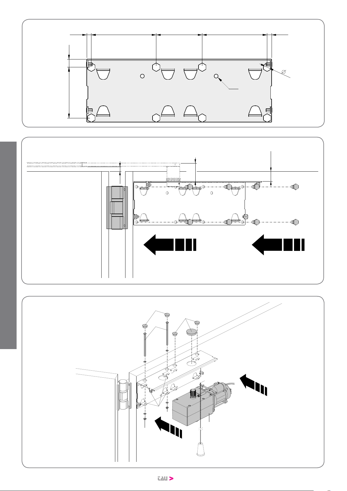
20
15
32,5
60
g.3
g.4
g.5
Ø 9
18.5
117
149.5 106
10
10.5 10.5149.5
A
B
D
C
E
F
F
G
G
BIUNO Series
DISEGNI - DRAWINGS - ZEICHNEN - PROJETS - DIBUJOS
This manual suits for next models
2
Table of contents
Languages:
Other tau Door Opening System manuals


