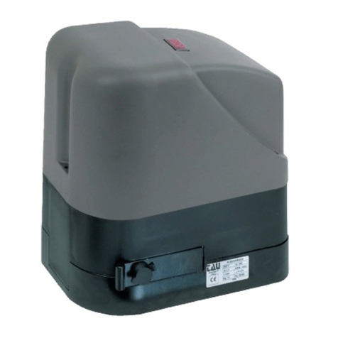
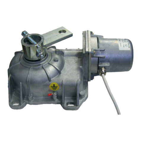
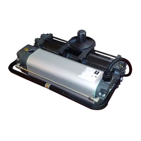
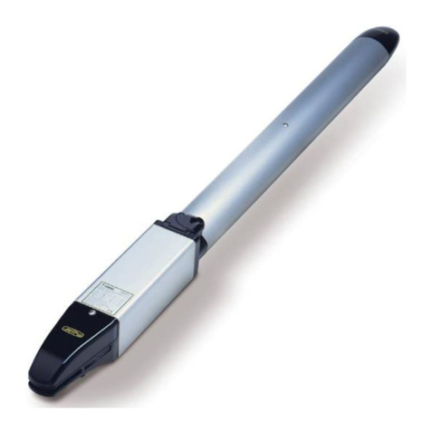
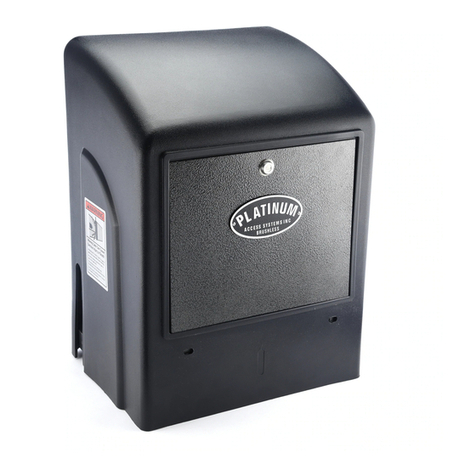
tau T-ONE User manual

1
T-ONE Series
MANUALE D’USO E MANUTENZIONE
USE AND MAINTENANCE MANUAL
BEDIENUNGS - UND WARTUNGSANLEITUNG
MANUEL D’EMPLOI ET D’ENTRETIEN
MANUAL DE USO Y MANTENIMIENTO
MANUAL DO UTILIZADOR E MANUTENÇÃO
T-ONE
Automatismo per Cancelli Scorrevoli - Uso Residenziale/Condominiale
Sliding Gate Operator - Residential/Communities
Schiebetorantrieb für Privat und Gewerbe
Automatisme pour Portails Coulissants – Usage Résidentiel/Intensif
Accionador para Puertas Correderas – Uso Residencial/Comunidades
Automatismo para Portões de Correr - Residencial/Condomínio
Via Enrico Fermi, 43 - 36066 Sandrigo (VI) Italia
Tel +39 0444 750190 - Fax +39 0444 750376 - info@tauitalia.com - www.tauitalia.com
IT - Istruzioni originali
D_MNL0TONE 08-10-2012 - Rev.11

2
T-ONE Series
Italiano
Español
English
Français
Deutsch
I dati riportati nel presente manuale sono puramente indicativi. La TAU si riserva il diritto di modicarli in qualsiasi momento.
La Casa costruttrice si riserva il diritto di apportare modiche o miglioramenti al prodotto senza alcun preavviso. Eventuali imprecisioni
o errori riscontrabili nel presente fascicolo, saranno corretti nella prossima edizione.
All’apertura dell’imballo vericare che il prodotto sia integro. Riciclare i materiali secondo la normativa vigente.
L’installazione del prodotto dovrà essere effettuata da personale qualicato. La Ditta costruttrice Tau declina ogni responsabilità
per danni derivanti a cose e/o persone dovuti ad un’eventuale errata installazione dell’impianto o la non messa a Norma dello
stesso secondo le vigenti Leggi (vedi Direttiva Macchine).
Los datos describidos en este manual son puramente indicativos. La TAU se reserva el derecho de modicarlos en cualquier
momento.
El Fabricante se reserva el derecho de modicar o actualizar el producto sin aviso previo. Posibles imprecisiones o errores en este
manual serán corregidos en la próxima edición.
Cuando abra el embalaje, controle que el producto esté íntegro. Recicle los materiales según la normativa vigente.
La instalación del producto tiene que ser efectuada por personal cualicado. El Fabricante Tau no se asume ninguna
responsabilidad por lesiones a personas o averías a cosas causadas por una instalación incorrecta del equipo o la por la
inobservancia de la normativa vigente (véase Directiva de Máquinas).
The data described in this handbook are purely a guide. TAU reserves the right to change them in any moment.
The manufacturer reserves the right to modify or improve products without prior notice. Any inaccuracies or errors found in this handbook
will be corrected in the next edition.
When opening the packing please check that the product is intact. Please recycle materials in compliance with current regulations.
This product may only be installed by a qualied tter. The manufacturer declines all liability for damage to property and/or
personal injury deriving from the incorrect installation of the system or its non-compliance with current law (see Machinery
Directive).
Les données décrites dans ce manual sont purement indicatives. La TAU se réserve le droit de les modier à n’importe quel moment.
Le Constructeur se réserve le droit d’apporter des modications ou des améliorations au produit sans aucun préavis. Les éventuelles
imprécisions ou erreurs présentes dans ce fascicule seront corrigées dans la prochaine édition.
À l’ouverture de l’emballage, vérier que le produit est intact. Recycler les matériaux suivant les normes en vigueur.
L’installation du produit devra être effectuée par du personnel qualié. Tau décline toute responsabilité pour les dommages
aux choses et/ou personnes dus à une éventuelle installation erronée de l’automatisme ou à la non-mise aux normes suivant
les lois en vigueur (voir Directive Machines).
Die beschriebenen Daten in der vorliegenden Betriebsanleitung sind rein indikativ. TAU behält sich vor, diese in jedem Moment zu
modizieren.
Der Hersteller behält sich das Recht vor, ohne vorherige Benachrichtung Änderungen oder Verbesserungen am Produkt anzubringen.
Ungenauigkeiten oder Fehler, die in der vorliegenden Ausgabe festgestellt werden, werden in der nächsten Ausgabe berichtigt.
Beim Öffnen der Verpackung prüfen, dass das Produkt keine Schäden aufweist. Die Materialien nach den gültigen Vorschriften
recyclen.
Die Installation des Produktes muss von Fachpersonal ausgeführt werden. Die Herstellerrma TAU übernimmt keinerlei
Haftung für Personen- und/oder Sachschäden aufgrund einer falschen Installation der Anlage oder der Nichtkonformität
derselben mit den gültigen Gesetzen (siehe Maschinenrichtlinie).
Os dados descritos neste manual são puramente indicativos. A TAU reserva-se no direito de o modicar a qualquer momento.
O fabricante reserva-se no direito de modicar ou actualizar o produto sem aviso prévio. Possíveis imprecisões ou erros neste manual
serão corrigidos na próxima edição / revisão.
Ao abrir a embalagem certique-se que o produto está intacto. Recicle os materiais segundo as normas em vigor.
Este producto só pode ser instalado por um técnico qualicado. O fabricante TAU declina qualquer responsabilidade por da-
nos pessoais ou materiais resultantes de uma instalação incorrecta do equipamento ou a sua não conformidade com a norma
vigente (Ver Directiva de Máquinas).
Português

3
T-ONE Series
T-ONE3B
Motoriduttore per can-
celli no a 300 Kg, mo-
tore 24V DC, quadro
elettrico incorporato.
Gearmotor for gates up
to 300 Kg, 24V DC mo-
tor, built-in control unit.
Getriebemotor für Tore
bis 300 Kg, 24V DC
Motor, mit eingebauter
Steuerzentrale.
Motoréducteur pour
portails jusqu’à 300
Kg, moteur 24V DC,
centrale incorporée.
Motorreductor para
verjas de hasta 300
Kg, motor de 24V DC,
central incorporada.
Motorredutor para
portões até 300Kg, 24V
DC, quadro incorpo-
rado
T-ONE5B
Motoriduttore per can-
celli no a 500 Kg, mo-
tore 12V DC, quadro
elettrico incorporato.
Gearmotor for gates up
to 500 Kg, 12V DC mo-
tor, built-in control unit.
Getriebemotor für Tore
bis 500 Kg, 12V DC
Motor, mit eingebauter
Steuerzentrale.
Motoréducteur pour
portails jusqu’à 500
Kg, moteur 12V DC,
centrale incorporée.
Motorreductor para
verjas de hasta 500
Kg, motor de 12V DC,
central incorporada.
Motorredutor para
portões até 500Kg, 12V
DC, quadro incorpo-
rado
T-ONE5
Motoriduttore per can-
celli no a 500 kg, moto-
re 230V AC con quadro
elettrico incorporato.
Gearmotor for gates
up to 500 Kg, 230V AC
motor, built-in control
unit.
Getriebemotor für Tore
bis 500 Kg, 230V AC
Motor, mit eingebauter
Steuerzentrale.
Motoréducteur pour
portails jusqu’à 500
Kg, moteur 230V AC,
centrale incorporée.
Motorreductor para
verjas de hasta 500
Kg, motor de 230V AC,
centrale incorporada.
Motorredutor para por-
tões até 500Kg, 230V
AC, quadro incorporado
T-ONE8
Motoriduttore per can-
celli no a 800 kg, moto-
re 230V AC con quadro
elettrico incorporato.
Gearmotor for gates
up to 800 Kg, 230V AC
motor, built-in control
unit.
Getriebemotor für Tore
bis 800 Kg, 230V AC
Motor, mit eingebauter
Steuerzentrale.
Motoréducteur pour
portails jusqu’à 800
Kg, moteur 230V AC,
centrale incorporée.
Motorreductor para
verjas de hasta 800
Kg, motor de 230V AC,
centrale incorporada.
Motorredutor para por-
tões até 800Kg, 230V
AC, quadro incorporado
T-ONEXL
Motoriduttore per can-
celli no a 1200 kg,
motore 230V AC con
quadro elettrico incor-
porato.
Gearmotor for gates up
to 1200 Kg, 230V AC
motor, built-in control
unit.
Getriebemotor für Tore
bis 1200 Kg, 230V AC
Motor, mit eingebauter
Steuerzentrale.
Motoréducteur pour
portails jusqu’à 1200
Kg, moteur 230V AC,
centrale incorporée.
Motorreductor para
verjas de hasta 1200
Kg, motor de 230V AC,
centrale incorporada.
Motorredutor para por-
tões até 1200Kg, 230V
AC, quadro incorporado
DATI TECNICI - TECHNICAL DATA - TECHNISCHE DATEN
DONNÉES TECHNIQUES - DATOS TÉCNICOS - DADOS TÉCNICOS
T-ONE3B T-ONE5B T-ONE5 T-ONE8 T-ONEXL
Frequenza - Frequency - Frequenz
Fréquence - Frecuencia - Frequência 50 - 60 Hz
Alimentazione - Power - Stromversorgung
Alimentation - Alimentación - Alimentação 230 V AC
Motore - Motor - Motor - Moteur - Motor - Motor 24 V DC 18 V DC 230 V AC
Condensatore - Condenser - Kondensator
Condensateur - Condensador - Condensador - - 12 µf
Corrente assorbita - Absorbed current - Stromaufnahme
Courant absorbé - Corriente absorbida - Corrente absorvida 1,7 A 0,85 A 1,2 A 1,3 A 2,1 A
Potenza assorbita - Absorbed power - Leistungsaufnahme
Puissance absorbée - Potencia absorbida - Potência absorvida
80 W 250 W 220 W 240 W 340 W
Spinta max. - Max. thrust - Max. Schub
Poussée max. - Empuje máx. - Pico de Força 320 N 980 N 920 N 1160 N 1160 N
Giri in uscita - Output revolutions - Drehzahl am Ausgang
Tours à la sortie - Revoluciones en salida - Rotações à saida 50 rpm 50 rpm 48 rpm
Velocità anta - Leaf speed - Flügelgeschwindigkeit
Vitesse du vantail - Velocidad hoja - Velocidade da folha 14 m/min 10,5 m/min
Grado di protezione - Protection level - Schutzart
Degré de protection - Grado de protección - Grau de protecção IP 44
Ciclo di lavoro - Work cycle - Arbeitszyklus
Cycle de travail - Ciclo de trabajo - Factor de serviço 100% 40% (see diagram)
Temperatura di esercizio - Operating temperature
Betriebstemperatur - Temperature de fonctionnement
Temperatura de trabajo - Temperatura de trabalho -20°C ÷ +55°C
Rapporto di riduzione - Reduction ratio
Untersetzungsverhältnis - Rapport de réduction
Relación de reducción - Rácio de redução 1/30
Intervento termoprotezione - Thermal protection trips at
Eingreifen des Wärmeschutzes - Intervention protection thermique
Activatión termoprotección - Activação protecção térmica -150°C
Peso max. cancello - Max. gate weight - Torgewicht max.
Poids max portail - Peso máximo de la cancela - Peso máximo portão
300 Kg 500 Kg 800 Kg 1200 Kg
Modulo pignone - Pinion module - Ritzel modul
Module pignon - Mòdulo piñón - Módulo pinhão 4 mm
Quando il sistema in 12V DC è alimentato unicamente dalla batteria (in caso di black-out oppure in abbinamento con
pannello fotovoltaico), le prestazioni espresse dal motoriduttore (forza e velocità) si riducono del 30% ca.
When the system is in the 12V DC mode and is powered by the battery only (in the event of a power failure or when used
in conjunction with a photovoltaic panel), the gear motor’s output (power and speed) is reduced by approximately 30%.
Anmerkung: wenn das 12V DC System nur über Batterie gespeist ist (bei Stromausfall oder in Kombination mit einem
Photovoltaicpaneel), verringern sich die leistungen des Getriebemotors (Kraft und Geschwindigkeit) um ca. 30%.
Attention : quand le système à 12V CC est alimenté uniquement par la batterie (en cas de coupure de courant ou bien
en association avec un panneau photovoltaïque), les performances du motoréducteur (force et vitesse) diminuent
d’environ 30% .
Nota: cuando el sistema de 12V DC es alimentado únicamente por la batería (en caso de corte de corriente, o bien com-
binado con panel fotovoltaico), las prestaciones del motorreductor (fuerza y velocidad) se reducen en un 30%.
Nota : Quando o sistema de 12VDC é alimentado únicamente pela bateria (em caso de falha de corrente ou quando
usado em combinação com painel fotovoltáico) as prestações do motor (velocidade e força) reduzem-se aproximada-
mente em 30%.

4
T-ONE Series
1_ AVVERTENZE PER L’INSTALLATORE
OBBLIGHI GENERALI PER LA SICUREZZA
1) Leggere attentamente le istruzioni prima di procedere
all’installazione, in quanto forniscono importanti indi-
cazioni concernenti la sicurezza, l’installazione, l’uso
e la manutenzione. Una errata installazione o un errato
uso del prodotto può portare a gravi danni alle perso-
ne.
2) I materiali dell’imballaggio (plastica, polistirolo, ecc.) non
devono essere lasciati alla portata dei bambini in quanto
potenziali fonti di pericolo.
3) Conservare le istruzioni per riferimenti futuri.
4) Questo prodotto è stato progettato e costruito esclusiva-
mente per l’utilizzo indicato in questa documentazione.
Qualsiasi altro utilizzo non espressamente indicato potreb-
be pregiudicare l’integrità del prodotto e/o rappresentare
fonte di pericolo.
5) TAU declina qualsiasi responsabilità derivata dall’uso im-
proprio o diverso da quello per cui l’automatismo è destina-
to.
6) Non installare il prodotto in ambiente e atmosfera esplosivi.
7) Gli elementi costruttivi meccanici devono essere in accordo
con quanto stabilito dalle Norme EN 12604 e EN 12605.
Per i Paesi extra-CEE, oltre ai riferimenti normativi nazio-
nali, per ottenere un livello di sicurezza adeguato, devono
essere seguite le Norme sopra riportate.
8) TAU non è responsabile dell’inosservanza della Buona Tec-
nica nella costruzione delle chiusure da motorizzare, non-
ché delle deformazioni che dovessero intervenire nell’utiliz-
zo.
9) Considerando i pericoli che si possono vericare durante
l’installazione e l’uso di T-ONE, per la massima sicurezza
è necessario che l’installazione avvenga nel pieno rispetto
di leggi, norme e regolamenti. In questo capitolo verranno
riportate avvertenze di tipo generico; altre importanti avver-
tenze sono presenti nei capitoli “3.1 Veriche preliminari”;
“8 Collaudo e messa in servizio”.
Secondo la più recente legislazione europea, la realiz-
zazione di una porta o cancello automatico ricade in
quanto previsto dalla Direttiva 2006/42/CE (Direttiva
Macchine) e nel particolare, alle norme: EN 12445; EN
12453 ed EN 12635, che consentono di dichiarare la
presunzione di conformità.
10) Prima di iniziare l’installazione è necessario eseguire analisi
dei rischi che comprendente l’elenco dei requisiti essenziali
di sicurezza previsti nell’allegato I della Direttiva Macchi-
ne, indicando le relative soluzioni adottate. Si ricorda che
l’analisi dei rischi è uno dei documenti che costituiscono il
“Fascicolo tecnico” dell’automazione.
11) Vericare la necessità di ulteriori dispositivi per completare
l’automazione con T-ONE in base alla specica situazione
d’impiego ed ai pericoli presenti; devono essere considerati
ad esempio i rischi di impatto, schiacciamento, cesoiamen-
to, convogliamento, ecc., ed altri pericoli in genere.
12) L’installazione deve essere effettuata nell’osservanza delle
Norme EN 12453 e EN 12445.
13) Prima di effettuare qualsiasi intervento sull’impianto, toglie-
re l’alimentazione elettrica e scollegare le batterie.
14) Prevedere sulla rete di alimentazione dell’automazione un
interruttore onnipolare con distanza d’apertura dei contatti
uguale o superiore a 3 mm. È consigliabile l’uso di un ma-
gnetotermico da 6A con interruzione onnipolare.
15) Vericare che a monte dell’impianto vi sia un interruttore
differenziale con soglia da 0,03 A.
16) Vericare che l’impianto di terra sia realizzato a regola d’ar-
te e collegarvi le parti metalliche della chiusura.
17) L’automazione dispone di una sicurezza intrinseca anti-
schiacciamento costituita da un controllo di coppia. E’ co-
munque necessario vericarne la soglia di intervento se-
condo quanto previsto dalle Norme indicate al punto 12.
18) I dispositivi di sicurezza (norma EN 12978) permettono di
proteggere eventuali aree di pericolo da Rischi meccanici
di movimento, come ad es. schiacciamento, convoglia-
mento, cesoiamento.
19) Per ogni impianto è consigliato l’utilizzo di almeno una se-
gnalazione luminosa nonché di un cartello di segnalazione
ssato adeguatamente sulla struttura dell’insso, oltre ai
dispositivi citati al punto 18.
20) TAU declina ogni responsabilità ai ni della sicurezza e del
buon funzionamento dell’automazione in caso vengano uti-
lizzati componenti dell’impianto non di produzione TAU.
21) Per la manutenzione utilizzare esclusivamente parti origi-
nali TAU.
22) Non eseguire alcuna modica sui componenti facenti parte
del sistema d’automazione.
23) L’automatismo non può essere utilizzato prima di aver effet-
tuato la messa in servizio come specicato nel capitolo:“5
Collaudo e messa in servizio”.
24) L’installatore deve fornire tutte le informazioni relative al
funzionamento manuale del sistema in caso di emergenza
e consegnare all’Utente utilizzatore dell’impianto la “Guida
Utente” allegata al prodotto.
25) Non permettere ai bambini o persone di sostare nelle vici-
nanze del prodotto durante il funzionamento.
26) Tenere fuori dalla portata dei bambini radiocomandi o qual-
siasi altro datore di impulso, per evitare che l’automazione
possa essere azionata involontariamente.
27) Il transito deve avvenire solo ad automazione ferma.
28) L’Utente utilizzatore deve astenersi da qualsiasi tentativo di
riparazione o d’intervento diretto e rivolgersi solo a perso-
nale qualicato.
29) Prima di accedere ai morsetti interni al coperchio di T-
ONE scollegare tutti i circuiti di alimentazione; se il di-
spositivo di sconnessione non è a vista apporvi un
cartello:“ATTENZIONE MANUTENZIONE IN CORSO”.
30) Manutenzione: effettuare almeno semestralmente la ve-
rica funzionale dell’impianto, con particolare attenzione
all’efcienza dei dispositivi di sicurezza (compresa, ove
previsto, la forza di spinta dell’operatore) e di sblocco.
31) Tutto quello che non è previsto espressamente in queste
istruzioni non è permesso.
Consigliamo di riporre tutta la documentazione relativa all’im-
pianto all’interno o nelle immediate vicinanze della centralina.
2_ DESCRIZIONE PRODOTTO E DESTINAZIONE
D’USO (g. 1)
T-ONE è un motoriduttore elettromeccanico per il movimento au-
tomatico di cancelli scorrevoli per uso residenziale, dispone di una
centrale elettronica di controllo con ricevitore incorporato per ra-
diocomando.
L’automazione è disponibile in più versioni: in 12V DC e in 230V
AC.
Il sistema irreversibile garantisce il blocco meccanico dell’anta
quando il motore non è in funzione. Un comodo e sicuro sistema
di sblocco con chiave personalizzata permette la movimentazione
manuale dell’anta in caso di disservizio o di mancanza di alimen-
tazione.
L’automazione T-ONE è stata progettata e costruita per
controllare l’accesso veicolare. Evitare qualsiasi altro
diverso utilizzo.
1_ Motoriduttore
2_ Centrale elettronica
3_ Pignone
4_ Sblocco manuale
5_ Carter di protezione
2.1_ Limiti d’impiego e dimensioni (g. 2)
I dati relativi alle prestazioni di T-ONE3B, T-ONE5B, T-ONE5, T-
ONE8 e T-ONEXL sono riportati nel capitolo “CARATTERISTICHE
TECNICHE” e sono gli unici valori che consentono la corretta valu-
tazione dell’idoneità all’uso.
Generalmente la serie T-ONE è in grado di automatizzare cancelli
con peso no a 300Kg (T-ONE3B), 500 Kg (T-ONE5B e T-ONE5),
800 Kg (T-ONE8) e 1200 Kg (T-ONEXL).
Curva di massimo utilizzo:
La curva consente di individuare il tempo massimo di lavoro (T) in
funzione della frequenza di utilizzo (F).
Es: Il motoriduttore T-ONE5 può funzionare ininterrottamente alla
frequenza d’utilizzo del 40%.
ITALIANO

5
T-ONE Series
ITALIANO
Per garantire il buon funzionamento è necessario operare nel cam-
po di lavoro sotto la curva.
Importante: la curva è ottenuta alla temperatura di 15 °C.
L’esposizione all’irraggiamento solare diretto può determinare di-
minuzioni della frequenza d’utilizzo no al 20%.
Calcolo della frequenza d’utilizzo:
E’ la percentuale del tempo di lavoro effettivo (apertura + chiusu-
ra) rispetto al tempo totale del ciclo (apertura + chiusura + tempi
sosta).
La formula di calcolo è la seguente:
dove:
Ta = tempo di apertura
Tc = tempo di chiusura
Tp = tempo di pausa
Ti = tempo di intervallo tra un ciclo completo e l’altro
Percentuale
di lav. %
% Frecuencia
de utilización
% factor
serviço
% Fréquence
d’utilisation
% Benutzungs-
frequenz
% Duty cycle
Tempo (h) Time (h) Zeit (Std.) Temps (h) Tiempo (h) Tempo (h)
10
10
100
90
80
70
60
50
40
30
20
2 3 4 5 6 7 8 9 10 11 12
2.2_ Impianto tipico
In gura 3 è riportato l’impianto tipico dell’automazione di un can-
cello di tipo scorrevole utilizzando T-ONE.
N° Descrizione
1Selettore a chiave
2Bordo primario sso (opzionale)
3 Fotocellule
4Bordo primario mobile
5 Staffa di necorsa “Aperto”
6 Cremagliera
7Bordo secondario sso (opzionale)
8 Lampeggiante con antenna incorporata
9Motoriduttore
10 Staffa di necorsa “Chiuso”
11 Sistema wireless
12 Battenti a pavimento
13 Bordo secondario mobile (opzionale)
Cablaggio:
Nell’impianto tipico di gura 3 sono indicati anche i cavi necessari
per i collegamenti dei vari dispositivi; in tabella sono indicate le
caratteristiche dei cavi.
Collegamento Tipo cavo
a: Linea elettrica di alimentazione
b: Lampeggiante
c: antenna
d: Fotocellule (TX)
e: Fotocellule (RX)
f: Selettore a chiave
g: Bordo sensibile primario
h: Bordi mobili
Rif. 230 V AC 12 V DC
a3x1,5mm² 3x1,5mm²
b2x0,5mm² 2x0,5mm²
cRG58 RG58
d2x0,5mm² (TX) 2x0,5mm² (TX)
e4x0,5mm² (RX) 4x0,5mm² (RX)
f* 3x0,5mm² 3x0,5mm²
g 2x0,5mm² 2x0,5mm²
h 2x0,5mm² 2x0,5mm²
* Se si installa anche l’art. P-300TSL, prevedere per il selettore a
chiave un cavo 5x0,5mm².
Note:
• se il cavo di alimentazione è più lungo di 30m occorre un cavo
con sezione maggiore, ad esempio 3x2,5mm² ed è necessaria
una messa a terra di sicurezza in prossimità dell’automazione.
Posizionare la centrale di comando (se esterna) nelle
immediate vicinanze dei motori.
Evitare che i cavi dei dispositivi ausiliari siano posizio-
nati all’interno di condutture dove sono presenti altri
cavi che alimentano grossi carichi o lampade con star-
ter elettronico.
Nel caso in cui vengano installati pulsanti di coman-
do o spie di segnalazione all’interno di abitazioni o di
edici che distano parecchi metri dalla centrale stessa,
è consigliabile disaccoppiare il segnale tramite relay
onde evitare disturbi indotti.
3_ INSTALLAZIONE
L’installazione di T-ONE deve essere effettuata da per-
sonale qualicato, nel rispetto di leggi, norme e rego-
lamenti e di quanto riportato nelle presenti istruzioni.
3.1_ Veriche preliminari
Prima di procedere con l’installazione di T-ONE è necessario ese-
guire questi controlli:
• Vericare che tutto il materiale da utilizzare sia in ottimo stato,
adatto all’uso e conforme alle norme.
• Vericare che la struttura del cancello sia adatta ad essere au-
tomatizzata.
• Vericare che il peso dell’anta rientri nei limiti di impiego ripor-
tati nel capitolo “2.1 Limiti d’impiego”
• Vericare che in tutta la corsa del cancello, sia in chiusura che
in apertura, non ci siano punti con maggiore attrito.
• Vericare che non vi sia pericolo di deragliamento dell’anta e
che non ci siano rischi di uscita dalle guide
• Vericare la robustezza degli arresti meccanici di oltrecorsa
controllando che non vi siano deformazioni anche se l’anta do-
vesse sbattere con forza sull’arresto.
• Vericare che l’anta sia in equilibrio cioè non deve muoversi se
lasciata ferma in una qualsiasi posizione.
• Vericare che la zona di ssaggio del motoriduttore non sia
soggetta ad allagamenti; eventualmente prevedere il montag-
gio del motoriduttore adeguatamente sollevato da terra.
• Vericare che la zona di ssaggio del motoriduttore permetta lo
sblocco ed una manovra manuale facile e sicura.
• Vericare che i punti di ssaggio dei vari dispositivi siano in
zone protette da urti e le superci siano sufcientemente soli-
de.
• Evitare che le parti dell’automatismo possano venir immerse in
acqua o in altre sostanze liquide
• Non porre T-ONE vicino a amme o fonti di calore; in atmosfere
potenzialmente esplosive, particolarmente acide o saline; que-
sto può danneggiare T-ONE ed essere causa di malfunziona-
menti o situazioni di pericolo.
• Nel caso sia presente un porta di passaggio interna all’anta
oppure una porta sull’area di movimento dell’anta, occorre as-
sicurarsi che non intralci la normale corsa ed eventualmente
provvedere con un opportuno sistema di interblocco
• Collegare la centrale ad una linea di alimentazione elettrica do-
tata di messa a terra di sicurezza.
• La linea di alimentazione elettrica deve essere protetta da un
adeguato dispositivo magnetotermico e differenziale.

6
T-ONE Series
• Muovere manualmente il cancello e procedere nelle operazioni
di ssaggio come per il primo elemento, proseguendo no alla
copertura completa del cancello.
Importante rispettare le misure di installazione e la di-
stanza tra dente dell’ingranaggio e dente cremagliera
come indicato nelle gg. 6 e 10.
Nota: la cremagliera deve scorrere sull’ingranaggio del
motoriduttore per l’intera larghezza del proprio dente
(g. 6).
Fissaggio della cremagliera (mod. 400CFZ12):
• Montare i tre nottolini lettati sull’elemento della cremagliera (A
g. 11) posizionandoli nella parte superiore dell’asola. In tale
modo il gioco sull’asola consentirà nel tempo le eventuali rego-
lazioni.
• Portare manualmente l’anta in posizione di apertura.
• Appoggiare sul pignone il primo pezzo di cremagliera a livello e
saldare il nottolino lettato sul cancello come indicato in g. 11.
• Muovere manualmente il cancello, vericando che la crema-
gliera sia in appoggio sul pignone e saldare il secondo e il terzo
nottolino.
• Accostare un altro elemento di cremagliera al precedente uti-
lizzando, per mettere in fase la dentatura dei due elementi, un
pezzo di cremagliera come indicato in g. 11.
• Muovere manualmente il cancello e saldare i tre nottolini letta-
ti proseguendo no alla copertura completa del cancello.
Importante rispettare le misure di installazione e la di-
stanza tra dente dell’ingranaggio e dente cremagliera
come indicato nelle gg. 9 e 11.
Nota: la cremagliera deve scorrere sull’ingranaggio del
motoriduttore per l’intera larghezza del proprio dente
(g. 9).
Fissaggio e regolazione pattini di necorsa (T-ONE5 / T-ONE8 / T-ONEXL):
• Fissare con i relativi grani le staffe di necorsa di “Apertura” e di
“Chiusura” ai lati estremi della cremagliera come in gura 10 e
11. Occorre considerare che quando intervengono i necorsa,
l’anta si muoverà per altri 2÷3 cm; è consigliabile quindi porre
le staffe di necorsa con opportuno margine sugli arresti mec-
canici.
È consigliato inoltre lubricare con un po’ d’olio il pun-
to di contatto del pattino di necorsa con la molla, al
ne di facilitare lo scivolamento e di evitare lo schiac-
ciamento di quest’ultima.
Nota: per una completa sicurezza si fa obbligo di instal-
lare, se non presenti, i fermi meccanici (battenti a pa-
vimento) con tappo in gomma, come mostrato in g. 3.
Può vericarsi, per effetto o somma di diversi fattori
(dilatazione termica, condizioni climatiche, frequenza
di utilizzo, etc.), una variazione, nell’arco della gior-
nata, del punto di arresto del cancello, sia per la fase
di apertura che per la fase di chiusura. Non è pertanto
possibile garantire che il cancello si fermi sempre nello
stesso punto.
3.3_ Versione con pignone a catena: Serie T-ONEC
Il portone può altresì essere motorizzato come indicato nella g.
12. Passare la catena come indicato in gura.
Nella g. 12 si riporta inoltre il tipo di catena richiesta (passo 1/2”
x 5/16”).
3.4_
Registrazione della frizione elettronica (T-ONE3B
e T-ONE5B), elettrica (T-ONE5, T-ONE8 e T-ONEXL)
ATTENZIONE: Vericare che il valore della forza d’im-
patto misurato nei punti previsti dalla norma EN 12445
sia inferiore a quanto indicato nella norma EN 12453.
• Tutti i motori della serie T-ONE sono dotati di encoder rego-
labile per il rilevamento degli ostacoli durante la corsa. Con l’
apposito potenziometro sulla scheda si può quindi impostare la
coppia massima di spinta.
3.5_ Installazione dei vari dispositivi
Effettuare l’installazione degli altri dispositivi previsti seguendo le
rispettive istruzioni. Vericare in gura 3 i dispositivi che possono
essere collegati a T-ONE.
3.2_ Installazione meccanica
Individuazione del sito:
• Scegliere una posizione analoga all’area tratteggiata di g. 4
nel caso si proceda al ssaggio diretto al suolo (predisporre
uno o più tubi per il passaggio dei cavi elettrici, 1 g. 4) se
questo è in calcestruzzo, oppure come in g. 5 quando c’è da
realizzare lo scavo, g. 5A (chiusura destra) o g. 5B (chiusura
sinistra).
Preparazione della base:
• Scavare le fondazioni per almeno 15 cm. di profondità e bene
allargate. Prevedere una guaina protettiva per i cavi.
Fissaggio della contropiastra di fondazione (mod. 400CPO):
• Ultimato lo scavo preparare la contropiastra di fondazione pie-
gando le zanche ricavate nella piastra dalla stessa parte dove
sono stati ricavati gli inserti (1 g.6) per il ssaggio del motori-
duttore mediante viti. Ricoprire con calcestruzzo annegando le
zanche e lasciando liberi gli inserti per il ssaggio del motori-
duttore; la contropiastra dovrà essere perfettamente piana ad 1
o 2 cm. dal livello del terreno e ad una distanza di 42 mm. circa
dal cancello (g. 6).
Fissaggio della contropiastra di fondazione (mod. 400CPOR):
• Assemblare la piastra di fondazione come da g.7.
• La piastra di fondazione deve essere posizionata come da
g.7A (chiusura destra) o g.7B (chiusura sinistra) per garanti-
re il corretto ingranamento tra il pignone e la cremagliera.
• Eseguire un plinto di fondazione come da g.5 e murare la
piastra di fondazione prevedendo una o più guaine per il pas-
saggio dei cavi elettrici. Vericare la perfetta orizzontalità della
piastra con una livella. Attendere che il cemento faccia presa.
• Predisporre i cavi elettrici per il collegamento con gli accessori
e l’alimentazione elettrica come da g.3.
Per effettuare agevolmente i collegamenti fare fuoriuscire i cavi
circa 30 cm dal foro della piastra di fondazione.
In alternativa si può utilizzare una contropiastra regolabile in altez-
za (P-550CPMR o P-550CPMR1 - g. 17) per la quale le zanche
sse devono essere saldate alla rotaia e successivamente bloc-
cate con 4 tasselli da fondazione M12x120 (vedi g. 18). Fissare
quindi la contropiastra regolabile come indicato in g. 19.
In questo modo è possibile adattare il motoriduttore ad un impianto
preesistente; vanno rispettate le misure indicate in g. 18.
Fissaggio del motoriduttore (su contropiastra mod. 400CPO):
• Ancorare il motoriduttore con n° 4 viti M8x30 e relative rondel-
le, come indicato in g. 8.
• Passare tutti i cavi attraverso i fori ricavati sulla base della con-
tropiastra di fondazione.
• Se la cremagliera è già presente, inserire n° 4 grani M8x30
(1 g. 8 - optionals) e n° 4 dadi M8 (2 g. 8 - optionals) per
regolare il pignone alla giusta altezza, lasciando 1÷2 mm di
gioco dalla cremagliera, vericando la perfetta orizzontalità del
motoriduttore con una livella.
Fissaggio del motoriduttore (su contropiastra mod. 400CPOR):
• Ancorare il motoriduttore alla contropiastra come indicato in g.
9, utilizzando n° 4 dadi M8 e n° 8 rondelle adeguate.
• Passare tutti i cavi attraverso i fori ricavati sulla base della con-
tropiastra di fondazione.
• Se la cremagliera è già presente, agire sui dadi (1 g. 9) per
regolare il pignone alla giusta altezza, lasciando 1÷2 mm di
gioco dalla cremagliera, vericando la perfetta orizzontalità del
motoriduttore con una livella.
Fissaggio della cremagliera (mod. 400CN):
• Sbloccare il motoriduttore come indicato nel paragrafo
“SBLOCCO MANUALE”.
• Aprire completamente l’anta, appoggiare sul pignone il primo
tratto di cremagliera e vericare che l’inizio della cremagliera
corrisponda all’inizio dell’anta come in gura 10. Vericare che
tra pignone e cremagliera vi sia un gioco di 1÷2 mm.
• Appoggiato sul pignone il primo pezzo di cremagliera a livello,
segnare il punto di foratura sul cancello; forare Ø 4 mm ed av-
vitare la vite autolettante Ø 6,3 mm.
• Muovere manualmente il cancello, vericando che la crema-
gliera sia in appoggio sul pignone e ripetere le operazioni dal
punto precedente.
• Accostare un altro elemento di cremagliera al precedente uti-
lizzando, per mettere in fase la dentatura dei due elementi, l'in-
castro a coda di rondine come indicato in g.10.
ITALIANO

7
T-ONE Series
4_ COLLEGAMENTI ELETTRICI
Prima di operare, assicurarsi che il motoriduttore non
sia elettricamente alimentato.
• Per effettuare i collegamenti, togliere il carter dal motoriduttore,
passare i cavi di alimentazione attraverso i fori ricavati sulla
contropiastra di fondazione (quando questa sia in uso) e at-
traverso il corpo inferiore del motoriduttore, quindi predisporli
per il collegamento alla morsettiera della scheda di comando
alloggiata nel supporto componenti elettrici.
• Usare cavi di sezione minima di 2,5 mm²per i circuiti di poten-
za (T-ONE3B e T-ONE5B) e di 1,5 mm² (T-ONE5, T-ONE8 e
T-ONEXL), di 0,5 mm²per i circuiti di comando.
Per i collegamenti alle schede comando consultare i relativi libretti
di istruzione:
- K120M per T-ONE3B;
- K125M per T-ONE5B;
- K580M per T-ONE5, T-ONE8 e T-ONEXL.
5_ INSTALLAZIONE BATTERIA 12V (T-ONE5B)
Se si vuole dotare il proprio motoriduttore di una batteria per ga-
rantire il funzionamento in assenza di corrente, togliere il carter
e inserirla nella apposita sede (g. 13); quindi collegare i cavi di
alimentazione alle linguette.
6_ SBLOCCO MANUALE
In assenza di tensione di linea levare il coperchietto della serra-
tura, inlare la apposita chiave e ruotare come indicato in g. 14.
Quindi, come in g. 15, tirare la leva verso l’esterno per ottenere la
gestione manuale del cancello.
7_ FINECORSA (T-ONE5 / T-ONE8 / T-ONEXL)
La serie T-ONE (230V AC) è studiata per fuzionare con dispositivo
di ne corsa elettro-meccanico a micro-switch.
I cavi sono collegati come in g. 16:
1= grigio (comune);
2= arancione (F.C. chiude - contatto N.C.);
3= rosso (F.C. apre - contatto N.C.);
4= grigio (comune).
Se, come rafgurato in fg. 16, quando l’ingranaggio ruota in senso
orario e la molla si sposta come indicato, la corsa non si ferma,
invertire la posizione dei li rosso ed arancione sulla morsettiera
della scheda di comando.
8_ VERIFICHE FINALI ED AVVIAMENTO
L’allacciamento dell’alimentazione a T-ONE deve esse-
re eseguito da personale esperto, qualicato, in pos-
sesso dei requisiti richiesti e nel pieno rispetto di leggi,
norme e regolamenti.
Non appena viene fornita tensione a T-ONE è consigliabile fare
alcune semplici veriche:
1. Vericare che i leds sulla scheda di comando siano accesi.
2. Vericare che il motore non comandi il movimento del portone
e che il lampeggiante sia spento.
Se tutto questo non avviene occorre spegnere imme-
diatamente l’alimentazione alla centrale e controllare
con maggiore attenzione i collegamenti elettrici.
Altre informazioni utili per la ricerca e la diagnosi dei guasti sono
presenti nel capitolo “7.6 Risoluzione dei problemi”.
Per gli altri parametri da impostare, apprendimento della corsa,
regolazione della frizione, rallentamento, regolazione tempo di
chiusura automatica, sensibilità rilevamento ostacoli etc., fare rife-
rimento alle istruzioni delle schede elettroniche.
9_ COLLAUDO E MESSA IN SERVIZIO
Questa è la fase più importante nella realizzazione dell’automazio-
ne al ne di garantire la massima sicurezza. Il collaudo può essere
usato anche come verica periodica dei dispositivi che compongo-
no l’automatismo.
Il collaudo dell’intero impianto deve essere eseguito da
personale esperto e qualicato che deve farsi carico
delle prove richieste, in funzione del rischio presente e
di vericare il rispetto di quanto previsto da leggi, nor-
mative e regolamenti, ed in particolare tutti i requisiti
della norma EN12445 che stabilisce i metodi di prova
per la verica degli automatismi per cancelli.
9.1_ Collaudo
Ogni singolo componente dell’automatismo, ad esempio bordi
sensibili, fotocellule, arresto di emergenza, ecc. richiede una spe-
cica fase di collaudo; per questi dispositivi si dovranno eseguire
le procedure riportate nei rispettivi manuali istruzioni.
Per il collaudo di T-ONE eseguire la seguente sequenza di ope-
razioni:
1. Vericare che sia stato rispettato rigorosamente tutto quanto
previsto nel presente manuale ed in particolare nel capitolo “1
Avvertenze”;
2. Utilizzando i dispositivi di comando o arresto previsti (selettore
a chiave, pulsanti di comando o trasmettitori radio), effettuare
delle prove di apertura, chiusura ed arresto del cancello e veri-
care che il comportamento corrisponda a quanto previsto.
3. Vericare uno ad uno il corretto funzionamento di tutti i disposi-
tivi di sicurezza presenti nell’impianto (fotocellule, bordi sensi-
bili, arresto di emergenza, ecc.);
4. Per la verica delle fotocellule ed in particolare che non vi siano
interferenze con altri dispositivi, passare un cilindro di diametro
5 cm e lunghezza 30 cm sull’asse ottico prima vicino al TX, poi
vicino all’RX e inne al centro tra i due e vericare che in tutti
i casi il dispositivo intervenga passando dallo stato di attivo a
quello di allarme e viceversa. Inne vericare che provochi nel-
la centrale l’azione prevista; esempio: nella manovra di chiusu-
ra provoca l’inversione di movimento.
5. Se le situazioni pericolose provocate dal movimento dell’anta
sono state salvaguardate mediante la limitazione della forza
d’impatto si deve eseguire la misura della forza secondo quan-
to previsto dalla norma EN 12445. Se la regolazione della “Ve-
locità” ed il controllo della “Forza Motore” vengono usati come
ausilio al sistema per la riduzione della forza d’impatto, provare
e trovare le regolazioni che offrono i migliori risultati.
9.2_ Messa in servizio
La messa in servizio può avvenire solo dopo aver ese-
guito con esito positivo tutte le fasi di collaudo di T-
ONE e degli altri dispositivi presenti. E’ vietata la mes-
sa in servizio parziale o in situazioni “provvisorie”.
• Realizzare e conservare per almeno 10 anni il fascicolo tecni-
co dell’automazione che dovrà comprendere almeno: disegno
complessivo dell’automazione, schema dei collegamenti elet-
trici, analisi dei rischi e relative soluzioni adottate, dichiarazio-
ne di conformità del fabbricante di tutti i dispositivi utilizzati (per
T-ONE utilizzare la Dichiarazione CE di conformità allegata);
copia del manuale di istruzioni per l’uso e del piano di manu-
tenzione dell’automazione.
• Apporre sul cancello una targhetta contenente almeno i se-
guenti dati: tipo di automazione, nome e indirizzo del costrutto-
re (responsabile della “messa in servizio”), numero di matrico-
la, anno di costruzione e marchio “CE”.
• Fissare in maniera permanente in prossimità del cancello un’e-
tichetta o una targa con indicate le operazioni per lo sblocco e
la manovra manuale.
• Realizzare e consegnare al proprietario la dichiarazione di con-
formità dell’automazione.
• Realizzare e consegnare al proprietario il manuale di “Istruzioni
ed avvertenze per l’uso dell’automazione”.
• Realizzare e consegnare al proprietario il piano di manutenzio-
ne dell’automazione (che deve raccogliere tutte le prescrizioni
sulla manutenzione dei singoli dispositivi).
• Prima di mettere in servizio l’automatismo informare adegua-
tamente ed in forma scritta il proprietario (ad esempio sul ma-
nuale di istruzioni ed avvertenze per l’uso dell’automazione)
sui pericoli ed i rischi ancora presenti.
ITALIANO

8
T-ONE Series
10_ USO
I motoriduttori della serie T-ONE sono stati progettati per movi-
mentare cancelli a scorrimento orizzontale con ante di peso mas-
simo di Kg. 300 (T-ONE3B), di Kg. 500 (T-ONE5B e T-ONE5), di
Kg. 800 (T-ONE8) e di Kg. 1200 (T-ONEXL).
Si fa espresso divieto di utilizzare l’apparecchio per
scopi diversi o in circostanze diverse da quelle men-
zionate.
La centralina elettronica installata consente di selezionare il fun-
zionamento:
automatico: un impulso di comando esegue l’apertura e la chiu-
sura del cancello;
semiautomatico: un impulso di comando esegue l’apertura o la
chiusura del cancello;
In caso di mancanza di energia elettrica, il cancello può funzio-
nare ugualmente grazie alla possibilità di gestione manuale, per
la quale è necessario agire sul dispositivo di sblocco manuale. I
modelli T-ONE3B e T-ONE5B, alimentabili con batterie tampone,
garantiscono il normale funzionamento dell’automazione anche in
caso di mancanza di tensione di rete.
Si ricorda che si è in presenza di un dispositivo automatico e ali-
mentato con corrente, perciò nell’utilizzo devono essere usate le
dovute precauzioni. In particolare, si raccomanda di:
• non toccare l’apparecchio con mani bagnate e/o piedi bagnati
o nudi;
• togliere la corrente prima di aprire la scatola comandi e/o il
motoriduttore;
• non toccare il motore se non siete sicuri che sia raffreddato;
• mettere in movimento il cancello solo quando è completamente
visibile;
• tenersi fuori dal raggio di azione del cancello se questo è in
movimento: aspettare no a che non sia fermo;
• non lasciare che bambini o animali giochino in prossimità del
cancello;
• non lasciare che bambini o incapaci usino il telecomando o altri
dispositivi di azionamento;
• effettuare una manutenzione periodica;
• in caso di guasto, togliere l’alimentazione e gestire il cancello
manualmente solo se possibile e sicuro. Astenersi da ogni in-
tervento e chiamare un tecnico autorizzato.
SI FA ESPRESSO DIVIETO DI LAVARE L’AUTOMAZIO-
NE UTILIZZANDO IDROPULITRICI O DISPOSITIVI SIMI-
LARI. È SEVERAMENTE VIETATO INDIRIZZARE GETTI
D’ACQUA DIRETTAMENTE SULL’AUTOMAZIONE.
11_ MANUTENZIONE
I motoriduttori della serie T-ONE necessitano di poca manutenzio-
ne. Tuttavia il loro buon funzionamento dipende anche dallo stato
del cancello: perciò descriveremo brevemente le operazioni da
fare per avere un cancello sempre efciente.
Attenzione: nessuna persona ad eccezione del manu-
tentore, che deve essere un tecnico specializzato, deve
poter comandare il cancello automatico durante la ma-
nutenzione.
Si raccomanda perciò di togliere l’alimentazione di rete evitando
così anche il pericolo di shock elettrici. Se invece l’alimentazione
dovesse essere presente per talune veriche, si raccomanda di
controllare o disabilitare ogni dispositivo di comando (telecomandi,
pulsantiere etc..) ad eccezione del dispositivo usato dal manuten-
tore.
Manutenzione ordinaria
Ciascuna delle seguenti operazioni deve essere fatta quando se
ne avverte la necessità e comunque ogni 6 mesi per un uso dome-
stico (circa 3000 cicli di lavoro) e ogni 2 mesi per un uso intensivo,
es. condominiale (sempre ogni 3000 cicli di lavoro).
Cancello
- Lubricare (con oliatore) le ruote di scorrimento del cancello;
- Vericare la pulizia e la tenuta della cremagliera;
Impianto di automazione
- Verica funzionamento dispositivi di sicurezza (fotocellule, co-
sta pneumatica, limitatore di coppia, etc..);
Manutenzione straordinaria
Se dovessero rendersi necessari interventi non banali su par-
ti meccaniche, si raccomanda la rimozione del motoriduttore per
consentire una riparazione in ofcina dai tecnici della casa madre
o da essa autorizzati.
12_ ACCESSORI OPZIONALI
La gamma dei motori della serie T-ONE è completata dai seguenti
accessori opzionali:
• P-650ESE03 sblocco manuale esterno provvisto di blindino;
• P-400FCM necorsa magnetico.
13_ RUMOROSITÀ
Il rumore aereo prodotto dal motoriduttore in condizioni normali di
utilizzo è costante e non supera i 70 dB.
14_ DEMOLIZIONE
L’eliminazione dei materiali va fatta rispettando le norme vigenti.
Nel caso di demolizione dell’automazione non esistono particolari
pericoli o rischi derivanti dall’automazione stessa.
È opportuno, in caso di recupero dei materiali, che siano separati
per tipologia (parti elettriche - rame - alluminio - plastica - etc...).
15_ SMANTELLAMENTO
Nel caso l’automazione venga smontata per essere poi rimontata
in altro sito è necessario:
- togliere l’alimentazione e scollegare tutto l’impianto elettrico;
- rimuovere il motoriduttore dalla base di ssaggio;
- smontare tutti i componenti dell’impianto;
- nel caso alcuni componenti non possano essere rimossi o ri-
sultino danneggiati, provvedere alla loro sostituzione.
16_ MALFUNZIONAMENTO: CAUSE E RIMEDI
Il cancello non apre, il motore non gira.
- Vericare che fotocellule o coste sensibili non siano sporche,
impegnate o non allineate. Procedere di conseguenza.
- Vericare che l’apparecchiatura elettronica sia regolarmente
alimentata, controllare l’integrità dei fusibili.
- Mediante i leds di diagnosi della centralina (vedere le rispettive
istruzioni), controllare se le funzioni sono corrette. Individua-
re eventualmente la causa del difetto. Se i leds indicano che
persiste un comando di start, controllare che non vi siano ra-
diocomandi, pulsanti di start o altri dispositivi che mantengono
attivato (chiuso) il contatto di start.
- Se la centralina non funziona, sostituirla.
Nel caso le condizioni sopra elencate diano esito negativo, sosti-
tuire il motoriduttore.
Il cancello non apre, il motore gira ma non avviene il movi-
mento.
- Lo sblocco manuale è rimasto inserito. Ripristinare il funziona-
mento motorizzato.
- Controllare se il cancello è in battuta negli arresti meccanici di
necorsa. Sbloccare manualmente il cancello, muoverlo e ripri-
stinare il funzionamento motorizzato. Controllare e correggere
la posizione dei pattini necorsa.
- Controllare che non vi siano difetti di assetto meccanico del
cancello.
Nel caso le condizioni sopra elencate diano esito negativo, sosti-
tuire il motoriduttore.
ITALIANO

9
T-ONE Series
DICHIARAZIONE DI INCORPORAZIONE DEL COSTRUTTORE
(ai sensi della Direttiva Europea 2006/42/CE AlI. II.B)
Fabbricante: TAU S.r.l.
Indirizzo: Via E. Fermi, 43
36066 Sandrigo (Vi)
ITALIA
Dichiara sotto la propria responsabilità che il prodotto: Attuatore elettromeccanico
realizzato per il movimento automatico di: Cancelli Scorrevoli
per uso in ambiente: Residenziale / Condominiale
completo di: Centrale elettronica di controllo e radioricevente
Modello: T-ONE
Tipo: T-ONE3B / T-ONE5B / T-ONE5 / T-ONE8 / T-ONEXL
Numero di serie: VEDI ETICHETTA ARGENTATA
Denominazione commerciale: AUTOMAZIONE PER CANCELLI SCORREVOLI
È realizzato per essere incorporato su una chiusura (cancello scorrevole) o per essere assemblato con altri dispositivi al ne di movi-
mentare una tale chiusura per costituire una macchine ai sensi della Direttiva Macchine 2006/42/CE.
Dichiara inoltre che questo prodotto è conforme ai requisiti essenziali di sicurezza delle seguenti ulteriori direttive CEE:
- 2006/95/CE Direttiva Bassa Tensione
- 2004/108/CE Direttiva Compatibilità Elettromagnetica
ed, ove richiesto, alla Direttiva:
- 1999/5/CE Apparecchiature Radio e apparecchiature terminali di telecomunicazione
Dichiara inoltre che non è consentito mettere in servizio il macchinario no a che la macchina in cui sarà incorporato o di cui diverrà
componente sia stata identicata e ne sia stata dichiarata la conformità alle condizioni della Direttiva 2006/42/CE.
Si impegna a trasmettere, su richiesta adeguatamente motivata delle autorità nazionali, informazioni pertinenti sulle quasi-macchine.
Sandrigo, 14/11/2011
Il Rappresentante Legale
_________________________________________
Bruno Danieli
Nome e indirizzo della persona autorizzata a costituire la documentazione tecnica pertinente:
Loris Virgilio Danieli - via E. Fermi, 43 - 36066 Sandrigo (Vi) Italia
ITALIANO

10
T-ONE Series
1_ INSTALLATION WARNINGS
GENERAL SAFETY REQUIREMENTS
1) Carefully read all instructions before installation, as
they provide important instructions regarding the safe-
ty, installation, operation and maintenance. Incorrect
installation or use of the product may lead to serious
physical injury.
2) Never leave packaging materials (plastic, polystyrene etc.)
within the reach of children as they constitute a potential
hazard.
3) Keep the instructions in a safe place for future consultation.
4) This product has been designed and constructed exclu-
sively for the use specied in this documentation. Any other
use not specied herein may impair product integrity and/or
constitute a hazard.
5) TAU declines all liability for improper use or use other than
as specied for this automation.
6) Never install the product in explosive atmospheres.
7) The mechanical elements must comply with the require-
ments as stated in the standards EN 12604 and EN 12605.
For non European member states, in addition to the na-
tional reference standards, the above-mentioned standards
must be observed to ensure an adequate level of safety.
8) TAU is not responsible for failure to observe Good Practice
in construction of the gates/doors to be power-operated,
nor any deformations occurring during use.
9) Considering the hazards that may occur during installation
and use of T-ONE, maximum safety is only ensured if the
product is installed in strict observance of current legisla-
tion,. standards and regulations. This chapter contains gen-
eral warnings, while other important warnings are provided
in chapters “3.1 Preliminary checks” and “8. Testing and
commissioning”.
According to the most recent legislation, the installa-
tion of a power-operated gate or door must be in full
observance of the standards envisaged by European
Directive 2006/42/EC (Machinery Directive) and in
particular the standards: EN 12445; EN 12453 and EN
12635, which enable the declaration of presumed con-
formity.
10) Before installation, an assessment of the associated risks
must be made, including a list of the essential safety re-
quirements as envisaged in Appendix I of the Machinery
Directive, specifying the relative solutions adopted. Note
that the risk assessment is one of the documents included
in the automation Technical documentation.
11) Check whether other devices are needed to complete the
T-ONE automation on the basis of the specic conditions
of use and dangers present; take into account all risks of
impact, crushing, shearing, dragging etc. and other hazards
in general.
12) Installation must be performed in compliance with the
standards EN 12453 and EN 12445.
13) Before performing any operations on the system, discon-
nect from the mains and detach the batteries.
14) On the automation power line, install a device for discon-
nection from the power mains with a gap between contacts
equal to or greater than 3 mm. Use of a 6A thermal mag-
netic circuit breaker with multi-pole switch is recommended.
15) Check upline of the system that there is a residual current
circuit breaker with a threshold of 0.03 A.
16) Ensure that the earthing system is to professional stand-
ards and connected to the metal section of the gate/door.
17) The automation is equipped with an intrinsic anti-crushing
safety device comprising a torque control. The trip thresh-
old must in all cases be checked as stated in the standards
specied in point 12.
18) The safety devices (standard EN 12978) enable the protec-
tion of danger areas from risks associated with mechani-
cal movements such as crushing, dragging and shearing.
19) The use of at least one luminous indicator is recommended
for each system, as well as a warning notice xed suitably
to the frame structure, in addition to the devices specied in
point 18.
20) TAU declines all liability for the safety and efcient opera-
tion of the automation in the event of using system compo-
nents not produced by TAU.
21) For maintenance, use exclusively original TAU parts.
22) Never modify components that are part of the automation
system.
23) The automation may only be used after completing the
commissioning procedure as specied in chapter 5 “Testing
and commissioning”.
24) The installer must provide all information regarding manual
operation of the system in the event of an emergency and
supply the system User with the “User Guide” enclosed with
the product.
25) Never allow children or other persons to stay in the vicinity
of the product during operation.
26) Keep all radio controls or other pulse supplier device out of
the reach of children to prevent inadvertent activation of the
automation.
27) Transit should only occur with the automation stationary.
28) The user must never attempt to repair or intervene directly
on the product; always contact qualied personnel for as-
sistance.
29) Before accessing internal terminals under the cover of T-
ONE, disconnect all power circuits. If the disconnect device
is not in a visible location, afx a notice stating “CAUTION:
MAINTENANCE IN PROGRESS”.
30) Maintenance: at least every six months, make a general
check of the system, with special reference to the efciency
of the safety devices (including, when envisaged, the op-
erator thrust force) and release mechanisms.
31) All actions not expressly envisaged in these instructions are
strictly prohibited.
All documentation related to the system should be kept inside
or in the immediate vicinity of the control unit.
2_ PRODUCT DESCRIPTION AND INTENDED USE
(g. 1)
T-ONE is an electromechanical gearmotor for the automatic move-
ment of sliding gates for residential applications, and is equipped
with an electronic control unit with built-in receiver for radio control.
There are several versions available: 12V DC and 230V AC.
The irreversible system guarantees mechanical blocking of the
gate when the motor is not operating. A practical and safe release
system with personalised key enables manual movement of the
gate in the event of a malfunction or power failure.
The T-ONE operator has been designed and construct-
ed to control vehicle access. Never use for other pur-
poses.
1_ Gearmotor
2_ Electronic control unit
3_ Pinion
4_ Manual release
5_ Protection guard
2.1_ Product application limits and dimensions (g. 2)
The data regarding the performance of T-ONE3B, T-ONE5B, T-
ONE5, T-ONE8 and T-ONEXL are stated in the chapter “TECHNI-
CAL SPECIFICATIONS” and are the only values that ensure the
correct assessment for suitability of use.
In general the series T-ONE is able to automate gates with a weight
of up to 300Kg (T-ONE3B), 500 Kg (T-ONE5B and T-ONE5), 800
Kg (T-ONE8) and 1200 Kg (T-ONEXL).
Maximum operating curve:
This curve enables identication of the maximum operating time
(T) according to the frequency of use (F).
E.g.: The T-ONE5 gearmotor can operate without interruption at a
frequency of use of 40%.
ENGLISH

11
T-ONE Series
ENGLISH
To guarantee optimal operation, the unit must operate within the
operating range below the curve.
Important: the curve is obtained at a temperature of 15 °C.
Exposure to direct sunlight may reduce the frequency of use by
up to 20%
Calculating the frequency of use:
This is the percentage of the effective operating time (opening and
closing) with respect to the total time of the cycle (opening + clos-
ing + pause time).
The calculation formula is as follows:
where:
Ta = Opening time
Tc = Closing time
Tp = Pause time
Ti = Interval time between one complete cycle and the next
Percentuale
di lav. %
% Frecuencia
de utilización
% factor
serviço
% Fréquence
d’utilisation
% Benutzungs-
frequenz
% Duty cycle
Tempo (h) Time (h) Zeit (Std.) Temps (h) Tiempo (h) Tempo (h)
10
10
100
90
80
70
60
50
40
30
20
2 3 4 5 6 7 8 9 10 11 12
2.2_ Typical system
Figure 3 shows a typical automation system for a sliding gate us-
ing T-ONE.
N° Description
1Key-operated selector switch
2Fixed primary edge (optional)
3 Photocells
4Mobile primary edge
5 “Open” limit switch bracket
6 Rack
7Secondary xed edge (optional)
8 Flashing light with built-in aerial
9 Gearmotor
10 “Closed” limit switch bracket
11 Wireless system
12 Floor-mounted end stops
13 Secondary mobile edge (optional)
Wiring:
The typical system in gure 3 also shows the cables required for
connecting the various devices; the table species the cable speci-
cations.
Connection Cable type
a: Mains power line
b: Flashing light
c: Antenna
d: Photocells (TX)
e: Photocells (RX)
f: Key-operated selector switch
g: Primary sensitive edge
h: Mobile edges
Ref. 230 V AC 12 V DC
a3x1,5mm² 3x1,5mm²
b2x0,5mm² 2x0,5mm²
cRG58 RG58
d2x0,5mm² (TX) 2x0,5mm² (TX)
e4x0,5mm² (RX) 4x0,5mm² (RX)
f* 3x0,5mm² 3x0,5mm²
g 2x0,5mm² 2x0,5mm²
h 2x0,5mm² 2x0,5mm²
* If art. P-300TSL is also installed, envisage a cable 5x0.5 mm for
the key selector switch.
Notes:
• If the power cable is longer than 30 m, a cable with a larger
cross-section is required (3 x 2.5 mm2) and safety earthing is
necessary in the vicinity of the automation.
Place the control unit (external versions) in the immedi-
ate vicinity of the motors.
Be careful not to run cables for auxiliary devices in-
side raceways housing other cables supplying power
to large loads or lights with electronic starters.
In the event control pushbuttons or indicator lights are
installed inside homes or ofces several metres from
the actual control unit, it is advisable to decouple the
signal by means of a relay in order to avoid induced
interference.
3_ INSTALLATION
T-ONE must be installed by qualied personnel, in
compliance with local legislation, standards, regula-
tions and these instructions.
3.1_ Preliminary checks
Before installing T-ONE, perform the following checks:
• Ensure that all material used is in perfect condition, suitable for
use and compliant with standards.
• Ensure that the gate structure is suitable for automation.
• Ensure that the weight of the leaf is within the application limits
as specied in paragraph 2.1 “Application limits”
• Ensure that there are no points of increased friction at any point
of gate travel, both in opening and closing.
• Ensure that there is no risk of gate derailing or risks of exit from
the tracks
• Check resistance of the mechanical overtravel stops, ensuring
there are no deformations even if the gate impact is strong on
stopping.
• Check that the leaf is balanced and therefore does not move if
left stationary in any position.
• Make sure that the xing zone is not subject to ooding. If nec-
essary, mount the gearmotor raised from the ground.
• Ensure that the gearmotor xing zone enables safe and easy
manual movement and release.
• Ensure that the selected surfaces for installation of the various
devices are solid, protected from the risk of impact and guar-
antee a stable xture.
• Ensure that parts of the automation cannot come into contact
with water or other liquids
• Never place T-ONE in the vicinity of ames or heat sources; in
potentially explosive, particularly acid or saline atmospheres,
this may damage T-ONE and cause malfunctions or hazardous
situations.
• If the gate leaf incorporates a pedestrian access door or if this
door is positioned in the gate movement area, ensure that this
does not prevent normal gate travel; if necessary install a com-
patible interlock system
• Connect the control unit to an electric power line equipped with
an earthing system.
• The mains power line must be protected by an adequate ther-
mal magnetic and residual current circuit breaker device.

12
T-ONE Series
3.2_ Mechanical installation
Site location:
• Choose a position similar to the outlined area in g. 4 when
xing the unit directly to the ground (lay one or two conduits
for routing electrical wiring, 1 g. 4) if in concrete, or as shown
in g. 5 when an excavation is required, g. 5A (right-hand clo-
sure) or g. 5B (left-hand closure).
Base preparation:
• Dig the foundations to a depth of at least 15 cm with sufcient
width. Fit a protective sheath for routing the electric cables.
Fixing the foundation plate assembly (model 400CPO):
• On completion of excavations, prepare the foundation plate as-
sembly by bending the anchor elements in the plate on the
same section mounting the inserts (1, g. 6) for xing the gear-
motor by means of screws. Embed the anchor elements in con-
crete while leaving the inserts exposed for gearmotor xture;
the foundation plate assembly must be perfectly at at 1 or 2
cm from ground level and at a distance of approx. 42 mm from
the gate (g. 6).
Fixing the foundation plate assembly (model 400CPOR):
• Assemble the foundation plate as shown in g. 7.
• The foundation plate must be positioned as shown in g.7A
(right-hand closure) or g.7B (left-hand closure) to guarantee
correct meshing of the pinion and rack.
• Make a foundation plinth as shown in g. 5 and install the foun-
dation plate, envisaging one or more conduit sheaths for rout-
ing the electric cables. Check perfect positioning of the plate
using a spirit level. Wait for the cement to set.
• Lay the electric cables for connection to the accessories and
electrical mains as shown in g. 3.
To facilitate connections, leave an excess length of cables of ap-
prox. 30 cm from the hole in the foundation plate.
Alternatively, a height adjustable base plate (P-550CPMR or P-
550CPMR1 - g. 17) can be used. In this case the xed ties must
be welded to the track and after locked with 4 expansion bold
M12x120 (see g. 18). The adjustable base plate is then secured
as indicated in g. 19.
In this way the gearmotor can be adapted to an already existing
system; the measurements indicated in g. 18 must be respected.
Fixing the gearmotor (on foundation plate assembly model
400CPO):
• Anchor the gearmotor using 4 screws M8x30 and relative
washers, as shown in g. 8.
• Pass all cables through the holes on the base of the foundation
plate assembly.
• If the rack is already present, insert the 4 stud bolts M8x30 (1
g. 8 - optional) and 4 nuts M8 (2 g. 8 - optional) to adjust the
pinion at the correct height, leaving 1÷2 mm of play from the
rack, checking perfect levelling of the gearmotor with a spirit
level.
Fixing the gearmotor (on foundation plate assembly model
400CPOR):
• Anchor the gearmotor to the foundation plate assembly as
shown in g. 9, using 4 nuts M8 and 8 washers.
• Pass all cables through the holes on the base of the foundation
plate assembly.
• If the rack is already present, adjust nuts (1 g. 9) to set the pin-
ion at the correct height, leaving 1÷2 mm of play from the rack,
checking perfect levelling of the gearmotor with a spirit level.
Fixing the rack (model 400CN):
• Release the gearmotor as described in the paragraph “MANU-
AL RELEASE”.
• Open the leaf completely, position the rst section of the rack
aligned with the edge of the gate and check that the start of the
rack corresponds to the start of the leaf as shown in gure 10.
Check that there is a clearance of 1÷2 mm between the pinion
and rack.
• After positioning the rst section of the rack aligned with the
edge of the gate, mark the drilling point on the gate, drill a Ø 4
mm hole and insert the self-tapping screw Ø 6,3 mm.
• Manually move the gate, checking that the rack is positioned
on the pinion and repeat the operations described in the previ-
ous point.
• Move another rack element up against the previous one, using
the dovetail connection to mesh the teeth of the two elements
as shown in g. 10.
• Manually move the gate and proceed with the xing operations
as per the rst element, through to complete coverage of the
gate.
It is very important to observe the installation measure-
ments and distance between the gear teeth and rack
teeth as shown in gures 6 and 10.
Note: the rack must slide on the gear of the gearmotor
throughout the entire length of its tooth (g. 6).
Fixing the rack (model 400CFZ12):
• Mount the three threaded pawls on the rack element (A g.
11) positioning them on the upper section of the slot. This will
ensure clearance on the slot for future adjustments when re-
quired.
• Manually move the leaf to the opening position.
• Position the rst section of the rack aligned with the edge of the
gate, and weld the threaded pawl onto the gate as shown in g.
11.
• Manually move the gate, checking that the rack is positioned
on the pinion and weld the second and third pawl.
• Move another rack element up against the previous one, using
a rack element to mesh the teeth of the two elements as shown
in g. 11.
• Manually move the gate and weld the three threaded pawls
through to complete coverage of the gate.
It is very important to observe the installation measure-
ments and distance between the gear teeth and rack
teeth as shown in gures. 9 and 11.
Note: the rack must slide on the gear of the gearmotor
throughout the entire length of its tooth (g. 9).
Fixing and adjusting the limit switch pads (T-ONE5 / T-ONE8 / T-ONEXL):
• With the relative stud bolts, x the “opening” and “closing” limit
switch brackets at the ends of the rack as shown in gure 10
and 11. Take into consideration that when the limit switches
trip, the leaf continues to move by a further 2÷3 cm; therefore
the limit switch brackets should be positioned with a suitable
margin on the mechanical stops.
It is also recommended to slightly lubricate the point
of contact of the limit switch pad with the spring, to
facilitate sliding and prevent compression of the latter.
Note: to ensure complete safety, mechanical stops
(oor-mounted end stops), if not already present, with
rubber caps MUST be tted, as shown in g. 3.
A single factor or combination of factors (thermal ex-
pansion, climate, frequency of use, etc.) may result in
the position the gate stops in changing over the course
of the day, both when opening and when closing. Con-
sequently, we cannot guarantee that the gate will al-
ways stop in the same position.
3.3_ Version with chain pinion: T-ONEC Series
The door can also be power-operated as shown in g. 12. Pass the
chain as shown in g.
Fig. 12 also shows the type of chain required (pitch 1/2” x 5/16”).
3.4_
Adjustment of the electronic clutch (T-ONE3B, T-ONE5B),
and electric clutch (T-ONE5, T-ONE8 and T-ONEXL)
IMPORTANT: Ensure that the impact force measured at
the points as envisaged by the standard EN 12445 is
less than the value specied in standard EN 12453.
• All motors in the T-ONE series are equipped with a settable en-
coder for obstacle detection during travel. The maximum thrust
torque can then be set by means of the relative potentiometer
on the card.
3.5_ Installation of various devices
To install the other devices envisaged, refer to the relevant instruc-
tions. Check in gure 3 the devices that can be connected to T-
ONE.
ENGLISH

13
T-ONE Series
ENGLISH
4_ ELECTRICAL CONNECTIONS
Before proceeding, ensure that the gearmotor is not
connected to the electrical mains.
• To make the connections, remove the cover from the gearmo-
tor, route the power cables through the holes on the founda-
tion plate assembly (if used) and through the lower body of the
gearmotor, then prepare them for connection to the terminal
board of the control card housed in the electrical components
support.
• Use cables with a minimum section of 2.5 mm² for the power
circuits (T-ONE3B and T-ONE5B) and 1.5 mm² (T-ONE5, T-
ONE8 and T-ONEXL), 0.5 mm² for the control circuits.
For connections to the control cards consult the relative instruction
booklets:
- K120M for T-ONE3B;
- K125M for T-ONE5B;
- K580M for T-ONE5, T-ONE8 and T-ONEXL.
5_ 12V BATTERY INSTALLATION (T-ONE5B)
If a battery is to be tted on the gearmotor to guarantee operation
in the event of a power failure, remove the cover and insert it in the
relative seat (g. 13); then connect the power cables to the tabs.
6_ MANUAL RELEASE
In the event of a power failure, raise the cover from the lock, insert
the relative key and turn as shown in g. 14.
Then, as shown in g. 15, pull the lever outwards to enable manual
movement of the gate.
7_ LIMIT SWITCH (T-ONE5 / T-ONE8 / T-ONEXL)
The series T-ONE (230 Vac) has been designed to operate with an
electro-mechanical micro-switch type limiter.
The cables are connected as shown in g. 16:
1= grey (common);
2= orange (F.C. close - NC contact);
3= red (F.C. Open - NC contact);
4= grey (common).
As shown in g. 16, when the gear rotates clockwise and the spring
moves as shown, if gate travel does not stop, invert the position of
the red and orange wires on the terminal board of the control card.
8_ FINAL CHECKS AND START-UP
T-ONE must be connected to the power mains by
skilled and qualied personnel, in possession of all
requirements for full compliance with all legal provi-
sions, standards and regulations.
Immediately after powering up T-ONE, perform a number of simple
checks:
1. Ensure that the leds on the control card are lit.
2. Ensure that the motor does not activate any gate movement
and that the ashing light is off.
If this is not so, disconnect the control unit from the
power supply immediately and check the electrical
connections carefully.
Other useful information for troubleshooting can be found in chap-
ter 7.6 “Troubleshooting”.
For other parameter settings, such as gate travel learning, clutch
adjustment, deceleration, automatic closure time, obstacle detec-
tion sensitivity etc., refer to the instructions of the electronic cards.
9_ TESTING AND COMMISSIONING
This is the most important phase of automation set-up to ensure
maximum system safety. The test can also be performed as a pe-
riodic check of automation devices.
Testing of the entire system must be performed by
skilled and qualied personnel, who are responsible
for the tests required to verify the solutions adopted
according to the risks present, and for ensuring ob-
servance of all legal provisions, standards and regula-
tions, with particular reference to all requirements of
the standard EN12445 which establishes the test meth-
ods for testing automations for power-operated gates.
9.1_ Testing
Each automation component, such as sensitive edges, photocells,
emergency stop, etc., requires a specic testing phase; for these
devices take care to follow the procedures specied in the respec-
tive instruction manual.
To test T-ONE, perform the following sequence of operations:
Ensure that all specications in this manual, and in particular chap-
ter “1 WARNINGS” have been strictly observed;
2. Using the control or stop devices envisaged (key-operated
selector switch, control pushbuttons, radio transmitters, etc.)
perform gate opening and closing tests, ensuring that the leaf
movement corresponds to specications.
3. Check operation of all system safety devices one at a time
(photocells, sensitive edges, emergency stop etc.);
4. To test photocells and in particular that there is no interference
with other devices, pass a cylinder (diameter 5 cm, length 30
cm) through the optic axis joining the pair of photocells, rst
close to the TX and then the RX and then mid-way between
the two. Ensure that in all cases the device engages, chang-
ing from the active status to alarm status and vice versa. Also
check that the envisaged action is generated in the control unit,
for example: that during the Closing manoeuvre, the door in-
verts the current movement.
5. If hazardous situations generated by the moving leafs are pro-
tected by means of impact force limitation, measure the force
as specied in the standard EN 12445. If the settings “speed”
and “gearmotor force” control are used as an auxiliary function
with the system for reduction of impact force, test and identify
the setting that obtains the best results.
9.2_ Commissioning
Commissioning can only be performed after positive
results of all test phases on T-ONE and other devices
present. Partial or “makeshift” commissioning is strict-
ly prohibited.
• Prepare the automation technical documentation (to be con-
served for at least 10 years), which must contain the follow-
ing documents: an overall layout diagram of the automation,
electrical wiring diagram, risk assessment and relative solu-
tions adopted, manufacturer’s declaration of conformity for all
devices used (for T-ONE use the CE declaration of conformity
enclosed) copy of instruction manual for operation and the au-
tomation maintenance schedule.
• Afx a dataplate on the gate, specifying at least the following
data: type of automation, name and address of manufacturer
(responsible for commissioning), serial number, year of con-
struction and CE mark.
• Permanently x a label or plate in the vicinity of the gate, stat-
ing the procedures for release and manual manoeuvres.
• Compile the automation declaration of conformity and deliver
to the owner.
• Compile the manual “Instructions and warnings for automation
operation” and deliver to the owner.
• Prepare the automation maintenance schedule (including all
instructions for the maintenance of individual devices) and de-
liver to the owner.
• Before commissioning the automation, ensure that the owner is
adequately informed in writing of all associated risks and haz-
ards (for example of the manual of instructions and warnings
for automation operation).
10_ OPERATION
The gearmotors in the series T-ONE have been designed to move
horizontal sliding gates with leafs of a maximum weight of 300 kg
(T-ONE3B), 500 kg (T-ONE5B and T-ONE5), 800 kg (T-ONE8)
and 1200 Kg (T-ONEXL).
Use of the device for other purposes or in other circum-
stances than as specied is strictly prohibited.
The electronic control unit installed enables selection of the operat-
ing mode:
automatic: a control pulse activates gate opening and closing;
semiautomatic: a control pulse activates gate opening or closing;
In the event of a power failure, the gate can still operate thanks
to the option of manual control, possible by means of the manual
release device.

14
T-ONE Series
The models T-ONE3B and T-ONE5B, with the optionals batteries
power supply guarantee normal automation operation also in the
event of a power failure.
Note that this is an automatic device and mains powered, and
therefore when used the due precautions must be taken. The fol-
lowing in particular is recommended:
• Never touch the device with wet hands and/or wet or bare feet;
• Disconnect the power supply before opening the controls box
and/or gearmotor;
• Never touch the motor before ensuring it is completely cool;
• Only move the gate when it is completely visible;
• Keep away from the operating range of the gate when in move-
ment: wait until it is stationary;
• never allow children or animals to play in the vicinity of the
gate;
• never allow children or unskilled persons to use the remote
control or other activation devices;
• Perform periodic maintenance;
• In the event of a fault, disconnect the power supply and only
move the gate manually when possible and in safety. Do not
intervene on the gate; call an authorised technician for assis-
tance.
CLEANING OF THE AUTOMATION WITH WATER JETS
OR SIMILAR DEVICES IS STRICTLY PROHIBITED. NEV-
ER DIRECT WATER JETS DIRECTLY ONTO THE AUTO-
MATION.
11_ MAINTENANCE
The gearmotors in the T-ONE series are low maintenance prod-
ucts. However efcient operation also depends on the condition of
the gate: Therefore a number of simple operations are described
below to maintain gate efciency.
Caution: No person other than the maintenance engi-
neer (who must be a specialised technician) must be
allowed to operate the automatic gate during mainte-
nance.
Therefore disconnect the device from the power mains to avoid the
risk of electric shock. However, if the power supply is required for a
number of checks, ensure that the control devices are controlled or
disabled (remote controls, pushbutton panels etc.) with the excep-
tion of the device used by the maintenance engineer.
Routine maintenance
Each of the following operations must be performed when deemed
necessary and in any event every 6 months in the case of domestic
use (approx. 3000 work cycles) and every 2 months in the case of
intensive use, e.g. apartment block (every 3000 work cycles).
Gate
- Lubricate (with a grease pump) the gate sliding wheels;
- Check the condition and stability of the rack;
Automation system
- Check operation of the safety devices (photocells, pneumatic
edge, torque limiter, etc..);
Special maintenance
If more complex operations are required on mechanical parts, the
gearmotor should be removed to enable repairs in the manufac-
turer’s workshop by technicians or other authorised centre.
12_ OPTIONAL ACCESSORIES
The range of T-ONE motors can be completed with the following
optional accessories:
•P-650ESE03 external manual release with armour-plated
case;
• P-400FCM magnetic limit switch.
13_ NOISE LEVELS
Airborne noise generated by the gearmotor in normal operating
conditions is constant and does not exceed 70 dB.
14_ SCRAPPING
All materials must be disposed of in observance of current stand-
ards.
If the automation is to be scrapped there are no particular dangers
or risks associated with the automation itself.
In the case of material recovery, separate components according
to the waste category (electrical parts - copper - aluminium - plas-
tic, etc.).
15_ DISASSEMBLY
If the automation is disassembled for subsequent re-assembly in
another site:
- Disconnect the power supply and the entire electrical system;
- Remove the gearmotor from the xing base;
- Disassemble all system components;
- If some components cannot be removed or are damaged, re-
place.
16_ MALFUNCTIONS TROUBLESHOOTING
The gate does not open, the motor does not work.
- Check that the photocells or sensitive edges are not dirty, en-
gaged or misaligned. Proceed according to the case in hand
- Check that the electrical equipment is powered correctly, check
all fuses.
- Check that all functions are correct via the control unit diagnos-
tic leds (see relative instructions). Locate the cause of the fault.
If the leds indicate that a start command persists, check that
there are no radio controls, start pushbuttons or other devices
that keep the start contact activated (closed).
- If the control unit does not work, replace.
If results are negative after the above proposed solutions, replace
the gearmotor.
The gate does not open, the motor turns but there is no move-
ment.
- The manual release is still engaged. Restore power operated
functions.
- Check that the gate is up against the mechanical limit stops.
Manually release the gate, move it and restore power-operat-
ed functions. Check and correct the position of the limitswitch
pads.
- Check that there are no defects in mechanical set-up of the
gate.
If results are negative after the above proposed solutions, replace
the gearmotor.
ENGLISH

15
T-ONE Series
ENGLISH
MANUFACTURER’S DECLARATION OF INCORPORATION
(in accordance with European Directive 2006/42/EC App. II.B)
Manufacturer: TAU S.r.l.
Address: Via E. Fermi, 43
36066 Sandrigo (Vi)
ITALY
Declares under its sole responsibility, that the product: Electromechanical actuator
designed for automatic movement of: Sliding Gates
for use in a: Residential / Communities
complete with: Electronic control unit and radioreceiver
Model: T-ONE
Type: T-ONE3B / T-ONE5B / T-ONE5 / T-ONE8 / T-ONEXL
Serial number: SEE SILVER LABEL
Commercial name: AUTOMATION FOR SLIDING GATES
Has been produced for incorporation on an access point (sliding gate) of for assembly with other devices used to move such an access
point, to constitute a machine in accordance with the Machinery Directive 2006/42/EC.
Also declares that this product complies with the essential safety requirements of the following EEC directives:
- 2006/95/EC Low Voltage Directive
- 2004/108/EC Electromagnetic Compatibility Directive
and, where required, with the Directive:
- 1999/5/CE Radio equipment and telecommunications terminal equipment
Also declares that it is not permitted to start up the machine until the machine in which it is incorporated or of which it will be a com-
ponent has been identied with the relative declaration of conformity with the provisions of Directive 2006/42/EC.
The manufacturer undertakes to provide, on sufciently motivated request by national authorities, all information pertinent to the quasi-
machinery.
Sandrigo, 14/11/2011
Legal Representative
_________________________________________
Bruno Danieli
Name and address of person authorised to draw up all pertinent technical documentation:
Loris Virgilio Danieli - via E. Fermi, 43 - 36066 Sandrigo (Vi) Italy

16
T-ONE Series
1_ HINWEISE FÜR DEN INSTALLATEUR
ALLGEMEINE PFLICHTEN BEZÜGLICH DER SICHER-
HEIT
1) Lesen Sie vor der Installation genau die Anweisungen,
da sie wichtige Hinweise bezüglich der Sicherheit, der
Installation, der Bedienung sowie der Wartung enthal-
ten. Eine falsche Installation oder eine falsche Anwen-
dung des Produkts kann zu schweren Verletzungen
führen.
2) Das Verpackungsmaterial (Kunststoff, Polystyrol usw.) darf
nicht in der Reichweite von Kindern aufbewahrt werden, da
es eine mögliche Gefahrenquelle darstellt.
3) Die Anleitungen für einen späteren Bedarf aufbewahren.
4) Dieses Produkt wurde ausschließlich für den in diesen Un-
terlagen angegebenen Zweck entwickelt und gebaut. Jede
andere nicht ausdrücklich angegebene Nutzung könnte die
Unversehrtheit des Produkts beeinträchtigen und/oder eine
Gefahrenquelle darstellen.
5) TAU lehnt jede Verantwortung für einen unsachgemäßen
oder nicht den Angaben entsprechenden Gebrauch der Au-
tomatisierung ab.
6) Das Produkt nicht in EX-gefährdeter Atmosphäre oder Um-
gebung installieren.
7) Die mechanischen Bauteile müssen mit den Vorschriften
der Norm EN 12604 und EN 12605 übereinstimmen. In au-
ßereuropäischen Ländern müssen außer den nationalen
Vorschriften auch die oben genannten Normen befolgt wer-
den, um eine ausreichende Sicherheitsstufe zu erreichen.
8) TAU übernimmt keinerlei Haftung im Falle von nicht fachge-
rechter Konstruktion der Toröffner oder im Falle von Verfor-
mungen derselben während des Gebrauchs.
9) Unter Berücksichtigung der Gefahren, die bei der Instal-
lation und Bedienung von T-ONE auftreten können, muss
die Installation zum Erhalt größter Sicherheit unter voller
Einhaltung von Gesetzen, Vorschriften und Verordnungen
erfolgen. In diesem Kapitel sind Hinweise allgemeiner Art
gegeben; weitere wichtige Hinweise benden sich in den
Kapiteln “3.1 Vorprüfungen”; “8 Abnahme und Inbetriebset-
zung”.
ACHTUNG: nach der neuesten europäischen Gesetz-
gebung, gehört die Ausführung einer automatischen
Tür oder eines automatischen Tors zu den Verordnun-
gen der Richtlinie 2006/42/EG (Maschinenrichtlinie)
und insbesondere zu den Vorschriften: EN 12445; EN
12453 und EN 12635, die es erlauben, die vermutliche
Konformität zu erklären.
10) Vor der Installation ist die Risikoanalyse auszuführen, wel-
che die Liste der wesentlichen Sicherheitsanforderungen,
vorgesehen in Anlage I der Maschinenrichtlinie, einschlie-
ßen und die jeweiligen, angewendeten Lösungen angeben
muss. Es wird daran erinnert, dass die Risikoanalyse eine
der Unterlagen ist, die Bestandteil der “Technischen Doku-
mentation“ der Automatisierung sind.
11) Je nach Einsatzbedingungen und vorhandenen Gefahren
prüfen, ob weitere Vorrichtungen erforderlich sind, um die
Automatisierung mit T-ONE zu vervollständigen; berück-
sichtigt werden müssen zum Beispiel Aufprall-, Quetsch-,
Schnitt- und Mitnehmgefahr usw. und sonstige Gefahren
allgemein.
12) Die Installation muss bei Einhaltung der Normen EN 12453
und EN 12445 vorgenommen werden.
13) Vor der Ausführung beliebiger Arbeiten an der Anlage die
Stromspeisung entfernen und die Batterien abtrennen.
14) Im Speisungsnetz der Automatisierung einen allpoligen
Schalter mit einer Öffnungsdistanz der Kontakte gleich
oder über 3 mm vorsehen. Wir empfehlen, einen 6A-Ma-
gnetthermoschalter mit einer allpoligen Unterbrechung zu
verwenden.
15) Prüfen, ob hinter der Anlage ein Differenzialschalter mit
max. 0,03 A vorliegt.
16) Prüfen, ob die Erdung fachgerecht ausgeführt wurde und
die Metallteile des Toröffners daran anschließen.
17) Die Automatisierung verfügt über einen eigenleitenden
Quetschschutz, der aus einer Drehmomentkontrolle be-
steht. Es ist auf jeden Fall notwendig, den Grenzwert ge-
mäß den Normen des Punkts 12 zu prüfen.
18) Die Sicherheitsvorrichtungen (Norm EN 12978) ermög-
lichen den Schutz eventueller Gefahrenbereiche vor me-
chanischen Bewegungsrisiken, wie z.B. Einquetschen,
Mitziehen, Schneiden.
19) Für jede Anlage sind die Verwendung mindestens einer
Leuchtanzeige und eines Hinweisschilds, das am Rahmen
befestigt wird, sowie die Vorrichtungen laut Punkt 18 emp-
fehlenswert.
20) TAU lehnt jede Haftung hinsichtlich der Sicherheit und der
Funktionstüchtigkeit der Automatisierung ab, falls nicht von
TAU hergestellte Anlagenteile verwendet werden.
21) Zur Instandhaltung ausschließlich TAU-Originalersatzteile
verwenden.
22) Keine Änderung an Bestandteilen des Automatisierungs-
systems ausführen.
23) Die Automatisierung darf erst verwendet werden, nachdem
die Inbetriebsetzung ausgeführt wurde, wie in Punkt “5 Ab-
nahme und Inbetriebsetzung“ vorgesehen.
24) Der Installateur muss alle Informationen bezüglich des ma-
nuellen Betriebs des Systems im Notfall weitergeben und
dem Anwender der Anlage die dem Produkt beigelegte „Be-
dienungsanleitung“ aushändigen.
25) Kindern oder anderen Personen nicht erlauben, während
des Betriebs in der Nähe des Produkts zu bleiben.
26) Fernsteuerungen oder andere Impulsgeber außerhalb der
Reichweite von Kindern aufbewahren, um zu vermeiden,
dass die Automatisierung ungewollt betätigt wird.
27) Der Durchgang darf nur bei stehender Automatisierung er-
folgen.
28) Der Anwender darf keine Reparatur oder direkte Eingriffe
vornehmen und muss sich hierzu an qualiziertes Personal
wenden.
29) Vor dem Zugriff auf die Klemmen im Deckel von T-ONE,
alle Kreisläufe der Speisung abtrennen; falls die Abtrenn-
vorrichtung nicht sichtbar ist, ein Schild mit der Aufschrift
:“ACHTUNG – WARTUNG IM GANG” anbringen.
30) Wartung: Mindestes alle sechs Monate die Funktionstüch-
tigkeit der Anlage prüfen, mit besonderer Beachtung der
Efzienz der Sicherheitsvorrichtungen (einschließlich der
Schubkraft der Automatisierung, wo vorhanden) und der
Entriegelungsvorrichtungen.
31) Alles nicht ausdrücklich in diesen Anweisungen vorgesehe-
ne ist unzulässig.
Wir empfehlen, die ganzen Unterlagen bezüglich der Anlage
innerhalb oder in der Nähe des Steuergeräts aufzubewahren.
2_
PRODUKTBESCHREIBUNG UND EINSATZ (Abb. 1)
T-ONE ist ein elektromechanischer Toröffner für die automatische
Bewegung von Schiebetoren an Wohngebäuden; er verfügt über
eine elektronische Steuerung und einen Empfänger für Funksteu-
erungen.
Die Automatisierung ist in mehreren Ausführungen erhältlich: mit
12V DC und mit 230V AC.
Das selbsthemmende System garantiert die mechanische Sperre
des Torügels, wenn der Antrieb nicht in Betrieb ist. Ein bequemes
und sicheres Entriegelungssystem mit individuellem Schlüssel er-
möglicht die Bewegung des Tors im Falle einer Störung oder bei
Stromausfall von Hand.
Die Automatisierung T-ONE wurde zur Kontrolle des
Fahrzeugszugangs entwickelt und gebaut. Jede andere
Verwendung vermeiden.
1_ Toröffner
2_ Elektronische Steuerung
3_ Ritzel
4_ Handentriegelung
5_ Schutzgehäuse
DEUTSCH

17
T-ONE Series
2.1_ Anwendungseinschränkungen und Abmessun-
gen (Abb. 2)
Die Leistungsdaten von T-ONE3B, T-ONE5B, T-ONE5, T-ONE8 und
T-ONEXL sind im Kapitel „Technische Merkmale” angegeben; nur
sie ermöglichen eine korrekte Bewertung der Anwendungsignung.
Generell ist die Serie T-ONE in der Lage, Tore mit einem Gewicht
bis zu 300 kg (T-ONE3B), 500 kg (T-ONE5B und T-ONE5), 800 kg
(T-ONE8), und 1200 Kg (T-ONEXL) zu automatisieren.
Kurve max. Verwendung:
Die Kurve ermöglicht die Herausstellung der Höchstbetriebszeit
(T) aufgrund der Anwendungsfrequenz (F).
z.B.: Der Toröffner T-ONE5 kann ununterbrochen mit einer Anwen-
dungsfrequenz von 40% in Betrieb sein.
Um eine gute Funktion zu gewährleisten, muss im Betriebsbereich
unter der Kurve vorgegangen werden.
Wichtig: Die Kurve wird bei einer Temperatur von 15°C erreicht.
Direkte Sonnenstrahlen können eine Verringerung der Anwen-
dungsfrequenz bis zu 20% verursachen.
Kalkulierung der Anwendungsfrequenz:
Das ist der Prozentwert der effektiven Betriebszeit (Öffnen +
Schließen) gegenüber der Gesamtzykluszeit (Öffnen + Schließen
+ Stoppzeiten).
Die Kalkulationsformel lautet:
Wobei:
Ta = Die Öffnungszeit
Tc = Die Schließzeit
Tp = Die Pausenzeit
Ti = Der Abstand zwischen einem vollständigen Zyklus und dem
nächsten sind.
Percentuale
di lav. %
% Frecuencia
de utilización
% factor
serviço
% Fréquence
d’utilisation
% Benutzungs-
frequenz
% Duty cycle
Tempo (h) Time (h) Zeit (Std.) Temps (h) Tiempo (h) Tempo (h)
10
10
100
90
80
70
60
50
40
30
20
2 3 4 5 6 7 8 9 10 11 12
2.2_ Typische Anlage
In Abbildung 3 ist die typische Anlage einer Schiebetorautomatisie-
rung mit T-ONE dargestellt.
NR. Beschreibung
1Schlüsseltaster
2Feste Hauptschaltleiste (Optional)
3 Photozellen
4Bewegliche Hauptschaltleiste
5 Bügel des Endschalters “Geöffnet”
6 Zahnstange
7Feste Nebenschaltleiste (Optional)
8 Blinkleuchte mit eingebauter Antenne
9 Toröffner
10 Bügel des Endschalters “Geschlossen”
11 Wireless-System
12 Bodendrehtor
13 Bewegliche Nebenschaltleiste (Optional)
Verkabelung:
In der typischen Anlage in Abbildung 3 sind auch die Kabel an-
gegeben, die zur Verbindung der verschiedenen Vorrichtungen
erforderlich sind; in der Tabelle sind die Merkmale der Kabel ver-
zeichnet.
Anschluss Kabeltyp
a: Stromleitung
b: Blinkleuchte
c: Antenne
d: Photozellen (TX)
e: Photozellen (RX)
f: Schlüsseltaster
g: Hauptschaltleiste
h: Bewegliche Schaltleisten
Bez. 230 V AC 12 V DC
a3x1,5mm² 3x1,5mm²
b2x0,5mm² 2x0,5mm²
cRG58 RG58
d2x0,5mm² (TX) 2x0,5mm² (TX)
e4x0,5mm² (RX) 4x0,5mm² (RX)
f* 3x0,5mm² 3x0,5mm²
g 2x0,5mm² 2x0,5mm²
h 2x0,5mm² 2x0,5mm²
* Wenn auch Art. P-300TSL installiert wird, für den Schlüsseltaster
ein Kabel 5x0,5 mm² vorsehen.
Anmerkungen:
• wenn das Versorgungskabel länger als 30m ist, muss ein Ka-
bel mit größerem Querschnitt benutzt werden, z.B. 3x2,5mm²
und eine Sicherheitserdung in der Nähe der Automatisierung
vorgesehen werden.
Positionieren Sie das Steuergerät (falls extern) in der
unmittelbaren Nähe der Motoren.
Vermeiden Sie es, die Kabel der Zusatzvorrichtungen
in den Kabelkanälen zu verlegen, in denen andere Ka-
bel vorhanden sind, die große Lasten oder Lampen mit
elektronischem Starter speisen.
Falls Tasten oder Kontrollleuchten in Wohnungen oder
Gebäuden installiert werden, die mehrere Meter vom
Steuergerät entfernt sind, empfehlen wir die Abkopp-
lung des Signals über ein Relais, um Störungen zu ver-
meiden.
3_ INSTALLATION
Die Installation von T-ONE muss von qualiziertem
Personal unter genauester Beachtung der Gesetze,
Vorschriften und Verordnungen und der Angaben in
den vorliegenden Anweisungen ausgeführt werden.
3.1_ Vorprüfungen
Vor der Installation von T-ONE müssen folgende Kontrollen aus-
geführt werden:
• Prüfen, ob das gesamte benutzte Material in bestem Zustand,
für den Einsatz geeignet und mit den Vorschriften konform ist.
• Prüfen, ob die Struktur des Tors so ausgelegt ist, dass es auto-
matisiert werden kann.
• Prüfen, ob sich das Gewicht des Torügels innerhalb der Ein-
satzgrenzen in Kapitel “2.1 Einsatzgrenzen” bendet.
• Prüfen, ob entlang dem gesamten Lauf des Tors sowohl in
Schließung als auch in Öffnung keine größeren Reibungen an-
liegen.
• Prüfen, ob der Torügel nicht ausgleiten und nicht aus den Füh-
rungen treten kann.
• Die Robustheit der mechanischen Überlaufanschläge kont-
rollieren und prüfen, dass keine Verformungen erfolgen, auch
wenn der Torügel heftig auf diese aufprallen sollte.
DEUTSCH

18
T-ONE Series
• Prüfen, dass der Torügel im Gleichgewicht ist: Er darf sich
nicht bewegen, wenn er in beliebiger Stellung stehen bleibt.
• Prüfen, ob sich der Bereich, in dem der Toröffner befestigt wird,
nicht überschwemmt werden kann; den Toröffner ggf. über
dem Boden installieren.
• Prüfen, ob die Entriegelung und eine leichte und sichere Be-
wegung von Hand des Torügels im Befestigungsbereich des
Toröffners möglich sind.
• Prüfen, ob sich die Befestigungsstellen der verschiedenen Vor-
richtungen in stoßgeschützten Bereichen benden und ob die
Oberächen ausreichend solide sind.
• Elemente der Automatisierung sollten nicht in Wasser oder an-
dere Flüssigkeit getaucht werden
• T-ONE nicht in der Nähe von Wärmequellen oder Flammen
oder in EX-gefährdeter, salz- oder säurehaltiger Umgebung
halten; dies kann Schäden und Betriebsstörungen in T-ONE
sowie Gefahren verursachen.
• Sollte der Torügel eine Eingangstür haben oder sich eine Tür
im Bewegungsbereich des Torügels bendet, ist sicher zu
stellen, dass diese den normalen Lauf des Tors nicht behindert;
ggf. für ein geeignetes Verblockungssystem sorgen.
• Die Steuerung an eine elektrische Versorgungsleitung mit Si-
cherheitserdung anschließen.
• Die elektrische Versorgungsleitung muss durch eine geeignete
magnetothermische Vorrichtung und Differentialschalter ge-
schützt sein.
3.2_ Mechanische Installation
Herausstellung des Orts:
• Eine ähnliche Position wie im gestrichelten Bereich der Abb.
4 suchen, falls eine direkte Befestigung am Boden erfolgt (ein
oder mehrere Rohre zum Durchführen der Stromkabel vorse-
hen, 1 Abb. 4), wenn dieser aus Beton ist, oder wie in Abb. 5
gezeigt, wenn ausgehoben werden muss, Abb. 5A (Schließen
rechts) oder Abb. 5B (Schließen links).
Vorbereitung der Montageplatte:
• Die Fundamente mindestens 15 cm tief und ausreichend breit
ausgraben. Einen Kabelschutzmantel vorsehen.
Befestigung der Fundamentgegenplatte (mod. 400CPO):
• Nach Abschluss der Aushebung die Fundamentgegenplatte
vorbereiten, indem die Mauerwangen in der Platte auf dieselbe
Seite gebogen werden, wo die Einsätze (1 Abb. 6) zur Befes-
tigung des Toröffners mittels Schrauben vorliegen. Mit Beton
ausgießen und die Mauerwangen bedecken, die Einsätze zur
Befestigung des Toröffners frei lassen; die Gegenplatte muss
1 oder 2 cm vom Boden abstehen und perfekt eben sein und
einen Abstand von ca. 42 mm vom Tor aufweisen (Abb. 6).
Befestigung der Fundamentgegenplatte (mod. 400CPOR):
• Die Fundamentplatte laut Abb. 7 zusammensetzen.
• Die Fundamentplatte muss wie in Abb. 7 A (Schließen rechts)
oder Abb. 7 B (Schließen links) platziert werden, um ein korrek-
tes Eingreifen des Ritzels in die Zahnstange zu gewährleisten.
• Eine Bodenplatte laut Abb. 5 ausführen und die Fundament-
platte einschließlich einer oder mehrerer Stromkabelrohre
einmauern. Die perfekte Waagrechtigkeit der Platte mit einer
Wasserwaage prüfen. Abwarten, bis der Beton erhärtet ist.
• Die Stromkabel zum Anschluss an die Zubehörteile und die
Stromspeisung laut Abb. 3 vorbereiten.
Um die Anschlüsse leicht auszuführen, die Kabel ca. 30 cm aus
der Öffnung der Fundamentplatte austreten lassen.
Alternativ kann eine höhenverstellbare Gegenplatte (P-550CPMR
oder P-550CPMR1 - Abb. 17) benutzt werden. In diesem Fall müs-
sen die festen Spreizbeine an das Gleis geschweißt werden und
witer befestigt mit 4 Fundament Dübeln M12 x 120 – siehe Abb.
18. Dann die verstellbare Gegenplatte wie auf Abb. 19 angegeben
befestigen.
Der Getriebemotor kann so einer bereits vorhandenen Anlage an-
gepasst werden; die in Abb. 18 angegebenen Maße sind einzu-
halten
Befestigung des Toröffners (auf Gegenplatte mod. 400CPO):
• Den Toröffner mit 4 Schrauben M8x30 und diesbezüglichen
Unterlegscheiben laut Abb. 8 befestigen.
• Alle Kabel durch die Öffnungen unter der Fundamentgegen-
platte durchziehen.
• Wenn die Zahnstange schon vorliegt, 4 Gewindebolzen M8x30
(1 Abb. 8 - Optionals) und 4 Muttern M8 (2 Abb. 8 – Optionals)
einsetzen, um das Ritzel auf die richtige Höhe zu bringen, wo-
bei 1-2 mm Spiel von der Zahnstange gelassen werden und die
perfekte Waagrechtigkeit des Toröffners mit einer Wasserwaa-
ge geprüft wird.
Befestigung des Toröffners (auf Gegenplatte mod. 400CPOR):
• Den Toröffner auf die Gegenplatte laut Abb. befestigen, wobei
4 Muttern M8 und 8 geeignete Unterlegscheiben verwendet
werden.
• Alle Kabel durch die Öffnungen unter der Fundamentgegen-
platte durchziehen.
• Wenn die Zahnstange schon vorliegt, über die Muttern (1 Abb.
das Ritzel auf die richtige Höhe bringen, wobei 1-2 mm Spiel
von der Zahnstange gelassen werden und die perfekte Waag-
rechtigkeit des Toröffners mit einer Wasserwaage geprüft wird.
Befestigung der Zahnstange (mod. 400CN):
• Den Toröffner wie im Abschnitt „HANDENTRIEGELUNG“ an-
gegeben entriegeln.
• Den Torügel ganz öffnen, das erste Teil der Zahnstange auf
das Ritzel legen und prüfen, dass der Anfang der Zahnstange
mit dem Anfang des Torügels gemäß Abbildung 10 überein-
stimmt. Prüfen, ob zwischen Ritzel und Zahnstange ein Spiel
von 1-2 mm vorliegt.
• Legen Sie auf das Ritzel das erste Teil der Zahnstange auf
Höhe Torkante. Die Bohrungsstelle am Tor anzeichnen, mit ei-
nem Durchm. von 4 m durchbohren und die selbst einschnei-
dende Schrauben Durchm. 6,3 mm einschrauben.
• Das Tor von Hand bewegen und prüfen, ob die Zahnstange auf
dem Ritzel liegt und die Vorgänge ab dem vorherigen Punkt
wiederholen.
• Ein anderes Zahnstangenteil an das vorherige legen und zur
Einstellung der Verzahnung der beiden Elemente die Schwal-
benschwanzeingreifung laut Abb. 10 benützen.
• Das Tor von Hand bewegen und die Befestigungen wie beim
ersten Teil bis zur vollständigen Abdeckung des Tors fortführen,
Es ist wichtig, die Installationsmaße und die Distanz
zwischen dem Zahn des Zahnrads und dem Zahnstan-
genzahn laut Abb. 6 und 10 einzuhalten.
Anmerkung: Die Zahnstange muss auf dem Zahnrad
des Toröffners über die ganze Breite des Zahns verlau-
fen (Abb. 6).
Befestigung der Zahnstange (mod. 400CFZ12):
• Die drei Gewindesperrzähne in das Zahnstangenteil montieren
(A Abb. 11) und sie auf dem oberen Bereich des Langlochs
platzieren. Auf diese Weise ermöglicht das Spiel im Langloch
spätere eventuelle Einstellungen.
• Den Torügel von Hand in die geöffnete Position verschieben.
• Legen Sie auf das Ritzel das erste Teil der Zahnstange auf
Höhe Torkante. Und den Gewindesperrzahn auf das Tor wie in
Abb. 11 angegeben schweißen.
• Das Tor von Hand bewegen und prüfen, ob die Zahnstange auf
dem Ritzel liegt und den zweiten und dritten Sperrzahn schwei-
ßen.
• Ein anderes Zahnstangenteil an das vorherige legen und zur
Einstellung der Verzahnung der beiden Elemente die Schwal-
benschwanzeingreifung laut Abb. 11 benützen.
• Das Tor von Hand bewegen und die drei Gewindesperrzähne
bis zur vollständigen Abdeckung des Tors schweißen.
Es ist wichtig, die Installationsmaße und die Distanz
zwischen dem Zahn des Zahnrads und dem Zahnstan-
genzahn laut Abb. 9 und 11 einzuhalten.
Anmerkung: Die Zahnstange muss auf dem Zahnrad
des Toröffners über die ganze Breite des Zahns verlau-
fen (Abb. 9).
DEUTSCH

19
T-ONE Series
DEUTSCH
Befestigung und Einstellung Endschalter (T-ONE5 / T-ONE8 / T-ONEXL):
• Die Endschalterbügel “Öffnung” und “Schließung” mit den je-
weiligen Stiftschrauben an den Außenseiten der Zahnstange,
wie in Abbildung 10 und 11 gezeigt, befestigen. Berücksich-
tigen, dass sich der Torügel bei Auslösung der Endschalter
noch ca. 2-3 cm weiter bewegt, daher die Endschalterbügel
etwas von den mechanischen Endanschlägen entfernt anbrin-
gen.
Es ist empfehlenswert, die Kontaktstelle des Endan-
schlags mit der Feder mit etwas Öl zu schmieren, um
das Gleiten zu erleichtern und das Einklemmen dieser
zu vermeiden.
Anmerkung: Für höchste Sicherheit müssen mecha-
nische Anschläge (Bodendrehtore) mit Gummikappe,
wie in Abb. 3 eingebaut werden, wenn diese noch nicht
vorhanden sind.
Durch die Auswirkung oder die Summe verschiedener
Faktoren (thermische Dilatation, klimatische Bedin-
gungen, Betriebsfrequenz usw.) kann es über den Tag
sowohl in der Phase der Öffnung, als auch in der Pha-
se der Schließung zu einer Variation des Anhaltepunkts
des Tors kommen. Es ist daher nicht möglich zu garan-
tieren, dass das Tor immer am gleichen Punkt anhält.
3.3_ Ausführung mit Kettenritzel: T-ONEC
Das Tor kann auch wie in Abb. 12 gezeigt angetrieben werden. Die
Kette wie in der Abbildung gezeigt durchziehen.
In der Abb. 12 wird außerdem die geforderte Kettenart aufgeführt
(Abstand 1/2“ x 5/16“).
3.4_
Einstellung der elektronischen (T-ONE3B, T-ONE5B),
elektrischen Kupplung (T-ONE5, T-ONE8, T-ONEXL)
ACHTUNG: Prüfen, ob der Wert der an den Stellen ge-
messenen Aufprallkraft laut Norm EN 12445 unter den
Angaben der Norm EN 12453 liegt.
• Alle Motoren der Serie T-ONE sind mit einstellbarem Encoder
zur Hinderniserfassung während des Laufs ausgestattet. Mit
dem hierfür vorgesehenen Potentiometer auf der Karte kann
das Höchstschubdrehmoment eingestellt werden.
3.5_ Installation der verschiedenen Vorrichtungen
Die Installation der anderen vorgesehenen Vorrichtungen nach
den jeweiligen Anweisungen ausführen. In der Abbildung 3 die Vor-
richtungen prüfen, die an T-ONE angeschlossen werden können.
4_ ELEKTRISCHE ANSCHLÜSSE
Vor allen Eingriffen sicherstellen, dass der Toröffner
nicht stromgespeist ist.
• Um die Anschlüsse auszuführen, das Gehäuse vom Toröff-
ner nehmen, die Speisungskabel durch die Öffnungen an der
Fundamentgegenplatte (wenn vorhanden) und durch den un-
teren Körper des Toröffners ziehen, dann für den Anschluss
am Klemmenbrett der Steuerkarte in der Halterung der elektri-
schen Bestandteile vorbereiten.
•
Ein Kabel mit einem Mindestschnitt von 2,5 mm² für die Leis-
tungskreise (T-ONE3B und T-ONE5B) und 1,5 mm² (T-ONE5, T-
ONE8 und T-ONEXL), 0,5 mm² für die Leistungskreise vorsehen.
Für die Anschlüsse an die Steuerkarten siehe diesbezügliche Ge-
brauchsanweisung:
- K120M für T-ONE3B;
- K125M für T-ONE5B;
- K580M für T-ONE5, T-ONE8 und T-ONEXL.
5_ INSTALLATION DER 12V-BATTERIE (T-ONE5B)
Wenn der Toröffner mit einer Batterie ausgestattet werden soll, um
einen Betrieb auch ohne Strom zu garantieren, das Gehäuse ent-
fernen und in den vorgesehenen Sitz (Abb. 13) einsetzen; Dann
die Speisungskabel an die Laschen schließen.
6_ HANDENTRIEGELUNG
Ohne Versorgungsspannung den Deckel des Schlosses anheben,
den hierfür vorgesehenen Schlüssel einstecken und wie in Abb. 14
gezeigt drehen.
Dann wie in Abb. 15 gezeigt, den Hebel nach außen ziehen, um
die Betätigung des Tors von Hand zu ermöglichen.
7_ ENDSCHALTER (T-ONE5 / T-ONE8 / T-ONEXL)
Die Serie T-ONE (230 Vac) wurde entwickelt, um mit dem elektro-
mechanischen Endanschlag mit Mikroswitch zu funktionieren.
Die Kabel sind wie in Abb. 16 angeschlossen:
1= grau (gemeinsam);
2 = orange (Endschalter schließt – N.C.-Kontakt);
3 = rot (Endschalter öffnet – N.C.-Kontakt);
4= grau (gemeinsam);
Wenn - wie in Abb. 16 dargestellt - das Zahnrad im Uhrzeigersinn
dreht und die Feder wie angegeben versetzt wird, hält der Lauf
nicht an – die Position des roten und orangefarbenen Kabels im
Klemmenbrett der Steuerkarte umkehren.
8_ ENDPRÜFUNGEN UND START
Der Anschluss der Versorgung von T-ONE muss von er-
fahrenem Fachpersonal mit den erforderlichen Kennt-
nissen und unter voller Einhaltung von Gesetzen, Vor-
schriften und Verordnungen ausgeführt werden.
Sobald T-ONE mit Spannung versorgt ist, sollten einige einfache
Überprüfungen ausgeführt werden:
1. Prüfen, ob die Leds in der Steuerkarte erleuchtet sind.
2. Prüfen, ob der Motor keine Torbewegung verursacht und ob
das Blinklicht abgeschaltet ist.
Sollte all dies nicht der Fall sein, muss die Versorgung
zur Steuerung unverzüglich ausgeschaltet werden,
dann die elektrischen Anschlüsse genauer kontrollie-
ren.
Weitere nützliche Auskünfte über die Fehlersuche und die Diag-
nose benden sich in Kapitel “7.6 Probleme und deren Lösung”.
Bezüglich anderer einzustellender Parameter, Erlernung des
Laufs, Einstellung der Kupplung, Verlangsamung, Einstellung der
automatischen Schließzeit, Empndlichkeit der Hinderniserfas-
sung usw., beziehen Sie sich bitte auf die Anleitungen der elektro-
nischen Steuerkarten.
9_ ABNAHME UND INBETRIEBNAHME
Um höchste Sicherheit zu gewährleisten, sind dies die wichtigsten
Schritte zur Ausführung der Automatisierung. Die Abnahme kann
auch als regelmäßige Überprüfung der Bestandteile der Automati-
sierung genützt werden.
Die Abnahme der gesamten Anlage muss von erfahre-
nem Fachpersonal ausgeführt werden, das die erforder-
lichen Tests je nach vorhandenem Risiko auszuführen
und die Einhaltung der von Gesetzen, Vorschriften und
Verordnungen vorgesehenen Punkte zu überprüfen
hat, und insbesondere alle Anforderungen der Norm
EN12445 sowie die Testmethoden zur Überprüfung von
Torautomatisierungen festlegt.
9.1_ Abnahme
Für jedes einzelne Element der Automatisierung wie zum Beispiel
Schaltleisten, Photozellen, Notstopps usw. ist eine spezielle Ab-
nahmephase erforderlich; für diese Vorrichtungen sind die Verfah-
ren in den jeweiligen Anleitungen auszuführen.

20
T-ONE Series
Für die Abnahme von T-ONE ist die folgende Sequenz auszufüh-
ren:
1. Prüfen, ob alles in der vorliegenden Anweisung und insbeson-
dere das in Kapitel 1 “HINWEISE” angegebene genauestens
eingehalten ist.
2. Die vorgesehenen Steuervorrichtungen (Schlüsseltaster, Steu-
ertasten oder Funksender) verwenden, die Schließung und
Öffnung des Tors testen und prüfen, ob das Verhalten wie vor-
gesehen ist.
3. Den korrekten Betrieb aller Sicherheitsvorrichtungen der Anla-
ge einzeln überprüfen (Photozellen, Schaltleisten, Notstopps
usw.).
4. Zur Überprüfung der Photozellen und insbesondere um zu prü-
fen, dass keine Interferenzen mit anderen Vorrichtungen vor-
handen sind, einen Zylinder mit 5 cm Durchmesser und 30 cm
Länge auf der optischen Achse zuerst nah an TX, dann nah an
RX und abschließend in ihrer Mitte durchführen und prüfen,
dass die Vorrichtung in allen Fällen ausgelöst wird und vom ak-
tiven Zustand auf den Alarmzustand übergeht und umgekehrt.
Dann prüfen, dass in der Steuerung der vorgesehene Vorgang
erfolgt, während der Schließung also zum Beispiel eine Um-
kehrung der Bewegung.
5. Falls die durch die Torbewegung verursachten Gefahren mittels
Begrenzung der Aufprallkraft abgesichert worden sind, muss
die Kraft nach den Verordnungen der Vorschrift EN 12445 ge-
messen werden. Falls die “Geschwindigkeitsregelung“ und die
Kontrolle der “Motorkraft” als Hilfsmittel für das System zur Auf-
prallkraftreduzierung benutzt werden, die Einstellungen erpro-
ben und diejenigen nden, mit denen die besten Ergebnisse
erzielt werden.
9.2_ Inbetriebsetzung
Die Inbetriebsetzung darf erst erfolgen, nachdem alle
Abnahmephasen von T-ONE sowie der anderen Vor-
richtungen erfolgreich beendet sind. Eine teilweise
oder vorübergehende Inbetriebsetzung ist unzulässig.
• Die technischen Unterlagen der Automatisierung zusammen-
stellen und diese mindestens 10 Jahre lang aufbewahren. Sie
müssen mindestens folgendes umfassen: Gesamtzeichnung
der Automatisierung, Schaltplan mit den elektrischen An-
schlüssen, Risikoanalyse und jeweilige angewendete Lösun-
gen, Konformitätserklärung des Herstellers für alle benutzten
Vorrichtungen (für T-ONE die anliegende “CE-Konformitätser-
klärung” verwenden); Kopie der Bedienungsanweisungen und
des Wartungsplans der Automatisierung.
• Bringen Sie am Tor ein Schild mit mindestens folgenden Daten
an: Automationstyp, Name und Adresse des Herstellers (Ver-
antwortlicher der “Inbetriebsetzung”), Seriennummer, Baujahr
und CE-Markierung.
• In Tornähe auf bleibende Art ein Etikett oder ein Schild befesti-
gen, dass die Angaben zur Durchführung der Entriegelung und
der Bewegung von Hand enthält.
• Die Konformitätserklärung der Automatisierung anfertigen und
dem Inhaber aushändigen.
• Das Handbuch “Anweisungen und Hinweise für die Bedienung
der Automatisierung“ anfertigen und dem Inhaber der Automa-
tisierung übergeben.
• Den Wartungsplan anfertigen und dem Inhaber der Automati-
sierung aushändigen. Er enthält die Wartungsvorschriften der
einzelnen Vorrichtungen.
• Vor der Inbetriebsetzung der Automatisierung, den Inhaber
auf geeignete Weise und schriftlich (z.B. in den “Anweisungen
und Hinweise für die Bedienung der Automatisierung“ über die
noch vorhandenen Gefahren und Risiken informieren.
10_ ANWENDUNG
Die Toröffner der Serie T-ONE wurde entwickelt, um Tore mit
waagrechtem Verlauf mit einem Torügel mit max. Gewicht von
300 kg (T-ONE3B), 500 kg (T-ONE5B und T-ONE5), 800 kg (T-
ONE8) und 1200 Kg (T-ONEXL) zu bewegen:
Die Verwendung der Einrichtung für andere Zwecke
oder unter anderen Umständen als genannt ist aus-
drücklich verboten.
Das installierte elektronische Steuergerät ermöglicht die Auswahl
der Betriebsart:
Automatisch: Ein Steuerimpuls führt das Öffnen und Schließen
des Tors aus;
Halbautomatisch: Ein Steuerimpuls führt das Öffnen oder Schlie-
ßen des Tors aus;
Bei Stromausfall kann das Tor dank der Handbetätigung trotzdem
bedient werden; hierfür wird die Handentriegelung benützt. Die
Schiebetorantriebe T-ONE3B und T-ONE5B können mit Puffer-
batterie funktionieren. Die Batterien garantieren einen normalen
Betrieb der Automatisierung auch bei Netzstromausfall.
Wir erinnern daran, dass es sich um eine automatische und strom-
gespeiste Vorrichtung handelt; somit müssen die notwendigen
Vorsichtsmaßnahmen beachtet werden. Insbesondere empfehlen
wir:
• Das Gerät nicht mit nassen Händen oder Füßen oder barfuss
zu berühren;
• Den Strom trennen, bevor das Steuergehäuse und/oder der
Toröffner geöffnet werden;
• Den Motor nicht berühren, bevor Sie nicht sicher sind, dass er
abgekühlt ist;
• Das Tor nur in Bewegung setzen, wenn es gut sichtbar ist;
• Sich außerhalb des Wirkungskreises des Tors aufhalten, wenn
dieses in Bewegung ist: Abwarten, bis es steht;
• Nicht zulassen, dass Kinder oder Tiere in der Nähe des Tors
spielen;
• Nicht zulassen, dass Kinder oder unfähige Personen die Fern-
steuerung oder andere Betätigungsvorrichtungen benützen;
• Eine regelmäßige Instandhaltung ausführen.
• Im Falle einer Störung, die Stromspeisung trennen und das Tor
von Hand bedienen, wenn dies möglich und sicher ist. Jegliche
Eingriffe vermeiden und einen zugelassenen Techniker rufen.
ES IST AUSDRÜCKLICH UNTERSAGT, DIE AUTOMATI-
SIERUNG MIT HYDROREINIGERN ODER ÄHNLICHEN
GERÄTEN ZU WASCHEN. ES IST STRENG VERBOTEN,
WASSER DIREKT AUF DIE AUTOMATISIERUNG ZU
SPRITZEN.
11_ WARTUNG
Die Toröffner der Serie T-ONE benötigen wenig Instandhaltung. Ihr
guter Betrieb hängt jedoch auch vom Zustand des Tors ab: Somit
beschreiben wir kurz die auszuführenden Arbeiten, um ein immer
efzientes Tor zu haben.
Achtung: Außer dem Wartungstechniker, der spezia-
lisiert sein muss, darf niemand das automatische Tor
während der Wartung steuern.
Wir empfehlen somit, die Stromspeisung zu trennen und so auch
die Gefahr eines Stromschlags zu vermeiden. Wenn die Speisung
dagegen für einige Prüfungen vorhanden sein muss, empfehlen
wir, jede Steuervorrichtung (Fernsteuerungen, Druckknopftafeln
usw.), außer der vom Wartungstechniker verwendeten Vorrich-
tung, zu kontrollieren oder zu deaktivieren.
Gewöhnliche Wartung
Jeder der folgenden Vorgänge muss ausgeführt werden, wenn er
für notwendig betrachtet wird und auf jeden Fall alle 6 Monate bei
einem Hausgebrauch (zirka 3000 Betriebszyklen) und alle 2 Mo-
nate bei einer intensiven Nutzung, z.B. Wohnanlagen (ebenso alle
3000 Betriebszyklen).
Tor
- Die Gleitrollen des Tors mit einer Ölkanne schmieren;
- Die Sauberkeit und Dichtheit der Zahnstange prüfen;
Automatisierungsanlage
- Die Funktion der Sicherheitsvorrichtungen prüfen (Photozel-
len, Pneumatikleiste, Drehmomentbegrenzer, usw.);
Außergewöhnliche Wartung
Wenn bedeutende Eingriffe an mechanischen Teilen notwendig
werden, empfehlen wir die Entfernung des Toröffners, um eine
Reparatur in der Werkstatt durch Techniker des Herstellers oder
durch zugelassene Techniker zu ermöglichen.
DEUTSCH
Other manuals for T-ONE
2
Table of contents
Languages:
Other tau Gate Opener manuals
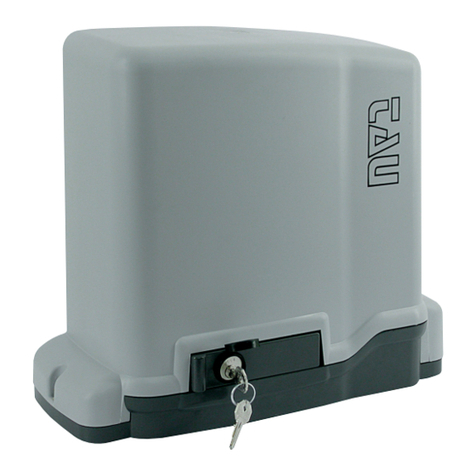
tau
tau MASTER Series User manual

tau
tau DAN Automatik MF30 User manual
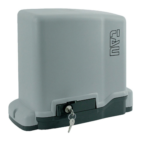
tau
tau MASTER User manual

tau
tau MASTER Series User manual
tau
tau 900TWM User manual
tau
tau ARM2000ENC User manual
tau
tau ARM 3000 Series User manual

tau
tau MASTER12Q User manual
tau
tau ARM200 Series User manual
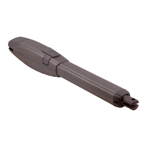
tau
tau ARM200 Series User manual
