tau R18 series User manual

R18-1
Serie R18
AUTOMAZIONI PER CANCELLO A BATTENTE
AUTOMATISIERUNG VON FLÜGELTOREN
AUTOMATIC SYSTEMS FOR SWING GATES
AUTOMATISATIONS POUR PORTAIL À BATTANT
SISTEMA DE AUTOMATIZACIÓN PARA VERJAS CON BATIENTES
MANUALE D’USO E MANUTENZIONE
BEDIENUNGS - UND WARTUNGSANLEITUNG
USE AND MAINTENANCE MANUAL
MANUEL D’EMPLOI ET D’ENTRETIEN
MANUAL DE USO Y MANTENIMIENTO
TAU srl via E. Fermi, 43 – 36066 Sandrigo (Vi) Italy – Tel. ++390444750190 Fax. ++390444750376 E-mail: [email protected]
Edizione 02 - anno 2005 rev. 09 - del 08/02/2006http://www.tauitalia.com
R18-2
AVVERTENZE E ISTRUZIONI PER L’INSTALLATORE
Tau si congratula per la scelta del prodotto e vi invita a leggere con molta attenzione queste pagine.
Al fine di renderle semplici, le istruzioni sono state impaginate seguendo l’ordine delle varie fasi d’installazione dell’impianto.
Leggere attentamente le istruzioni prima di procedere all’installazione, in quanto forniscono importanti indicazioni concernenti la
sicurezza, l’installazione, l’uso e la manutenzione.
Tutto quello che non è espressamente previsto nel presente manuale NON è permesso.
Usi non indicati, infatti, potrebbero essere causa di danni al prodotto stesso e mettere in pericolo persone, animali e/o cose.
L’installazione deve essere eseguita da personale qualificato, professionalmente competente.
L’installazione, i collegamenti elettrici e le regolazioni devono essere effettuati nell’osservanza della Buona Tecnica e in ottemperanza
alle norme vigenti.
Prima di iniziare l’installazione verificare l’integrità del prodotto.
Non installare il prodotto in ambiente e atmosfera esplosivi.
Prima di installare l’automazione, apportare tutte le modifiche strutturali relative alla realizzazione dei franchi di sicurezza ed alla
protezione o segregazione di tutte le zone di schiacciamento, cesoiamento, convogliamento e di pericolo in genere. Verificare che la
struttura esistente abbia i necessari criteri di robustezza e stabilità.
I dispositivi di sicurezza (fotocellule, coste sensibili, stop di emergenza, ecc.) devono essere installati tenendo in considerazione: le
normative e le direttive in vigore, i criteri della Buona Tecnica, l’ambiente di installazione, la logica di funzionamento del sistema e le
forze sviluppate dalla porta o cancello motorizzati.
Applicare le segnalazioni previste dalle norme vigenti per individuare le zone pericolose. Ogni installazione deve riportare in modo
visibile l’indicazione dei dati identificativi degli organi automatizzati.
Prima di collegare l’alimentazione elettrica accertarsi che i dati di targa siano rispondenti a quelli della rete di distribuzione elettrica.
Prevedere sulla rete di alimentazione un interruttore/sezionatore onnipolare con distanza d’apertura dei contatti uguale o superiore a
3 mm.
Verificare che a monte dell’impianto elettrico vi siano un interruttore differenziale e una protezione di sovracorrente adeguati (interruttore
magnetotermico C6).
Collegare l’automazione a un’efficace impianto di messa a terra eseguito come previsto dalle vigenti norme di sicurezza.
Il costruttore dell’automazione declina ogni responsabilità qualora vengano installati componenti incompatibili ai fini della sicurezza
e del buon funzionamento. Per l’eventuale riparazione o sostituzione dei prodotti dovranno essere utilizzati esclusivamente ricambi
originali.
L’installatore deve fornire tutte le informazioni relative al funzionamento automatico, manuale e di emergenza della struttura
automatizzata, e consegnare all’utilizzatore dell’impianto le istruzioni per l’uso.
Consigliamo di riporre tutta la documentazione relativa all’impianto all’interno o nelle immediate vicinanze della centralina.
Italiano
I - La Casa costruttrice si riserva il diritto di apportare modifiche o miglioramenti al prodotto senza alcun preavviso. Eventuali
imprecisioni o errori riscontrabili nel presente fascicolo, saranno corretti nella prossima edizione.
All’apertura dell’imballo verificare che il prodotto sia integro. Riciclare i materiali secondo la normativa vigente.
L’installazione del prodotto dovrà essere effettuata da personale qualificato. La Ditta costruttrice Tau declina ogni responsabilità
per danni derivanti a cose e/o persone dovuti ad un’eventuale errata installazione dell’impianto o la non messa a Norma dello
stesso secondo le vigenti Leggi (vedi Direttiva Macchine).
D - Der Hersteller behält sich das Recht vor, ohne vorherige Benachrichtung Änderungen oder Verbesserungen am Produkt
anzubringen. Ungenauigkeiten oder Fehler, die in der vorliegendenAusgabe festgestellt werden, werden in der nächstenAusgabe
berichtigt.
Beim Öffnen der Verpackung prüfen, dass das Produkt keine Schäden aufweist. Die Materialien nach den gültigen Vorschriften
recyclen.
Die Installation des Produktes muss von Fachpersonal ausgeführt werden. Die Herstellerfirma TAU übernimmt keinerlei Haftung
für Personen- und/oder Sachschäden aufgrund einer falschen Installation derAnlage oder der Nichtkonformität derselben mit den
gültigen Gesetzen (siehe Maschinenrichtlinie).
GB - The manufacturer reserves the right to modify or improve products without prior notice. Any inaccuracies or errors found in this
handbook will be corrected in the next edition.
When opening the packing please check that the product is intact. Please recycle materials in compliance with current
regulations.
This product may only be installed by a qualified fitter.The manufacturer declines all liability for damage to property and/or personal
injury deriving from the incorrect installation of the system or its non-compliance with current law (see Machinery Directive).
F - Le Constructeur se réserve le droit d’apporter des modifications ou des améliorations au produit sans aucun préavis. Les
éventuelles imprécisions ou erreurs présentes dans ce fascicule seront corrigées dans la prochaine édition.
À l’ouverture de l’emballage, vérifier que le produit est intact. Recycler les matériaux suivant les normes en vigueur.
L’installation du produit devra être effectuée par du personnel qualifié. Tau décline toute responsabilité pour les dommages aux
choses et/ou personnes dus à une éventuelle installation erronée de l’automatisme ou à la non-mise aux normes suivant les lois
en vigueur (voir Directive Machines).
E - El Fabricante se reserva el derecho de modificar o actualizar el producto sin aviso previo. Posibles imprecisiones o errores en
este manual serán corregidos en la próxima edición.
Cuando abra el embalaje, controle que el producto esté íntegro. Recicle los materiales según la normativa vigente.
La instalación del producto tiene que ser efectuada por personal cualificado. El Fabricante Tau no se asume ninguna
responsabilidad por lesiones a personas o averías a cosas causadas por una instalación incorrecta del equipo o la por la
inobservancia de la normativa vigente (véase Directiva de Máquinas).
D-MNL0R18

R18-3
HINWEISE UND ANWEISUNGEN FÜR DEN INSTALLATEUR
Tau gratuliert Ihnen zur Wahl dieses Produkts und bittet Sie, diese Seiten sehr aufmerksam zu lesen.
Um die Anweisungen einfach zu machen, wurden sie in der Reihenfolge der verschiedenen Installationsphasen der Anlage verfasst.
Die Anweisungen vor der Installation genau lesen, da sie wichtige Hinweise mit Bezug auf Sicherheit, Installation, Bedienung und
Wartung liefern.
Alles nicht ausdrücklich in diesen Anleitungen vorgesehene ist UNZULÄSSIG.
Ein nicht angegebener Gebrauch könnte Schäden am Produkt verursachen und Personen, Tiere und/oder Gegenstände in Gefahr
bringen.
Die Installation muss von beruflich kompetentem Fachpersonal ausgeführt werden.
Installation, elektrische Anschlüsse und Einstellungen sind unter Beachtung der Fachtechnik und der gültigen Vorschriften
auszuführen.
Das Produkt vor der Installation auf Schäden überprüfen.
Das Produkt nicht in EX-Umgebung bzw. EX-Atmosphäre installieren.
Vor der Installation der Automatisierung alle strukturellen Änderungen für das Vorhandensein der Sicherheitsabstände und den Schutz
aller Bereiche ausführen, in denen Quetsch-, Schnitt- und Mitnehmgefahr und Gefahren allgemein bestehen. Prüfen, ob die vorhandene
Struktur die erforderliche Robustheit und Stabilität besitzt.
Sicherheitsvorrichtungen (Fotozellen, Sicherheitsleisten, Notstop usw.) müssen unter Berücksichtigung des folgenden installiert
werden: gültige Vorschriften und Verordnungen, korrekte Fachtechnik, Installationsumgebung, Betriebslogik des Systems und Kräfte,
die vom motorbetriebenen Tor entwickelt werden.
Zur Kennzeichnung von Gefahrenbereichen die laut gültigen Vorschriften vorgesehenen Beschilderungen anbringen. An jeder
Installation müssen die Kenndaten der automatisierten Elemente sichtbar angegeben sein.
Vor dem Anschluss der Stromversorgung ist sicher zu stellen, dass die Kenndaten mit jenen des Stromnetzes übereinstimmen.
Am Versorgungsnetz einen allpoligen Schalter/Trennschalter mit Öffnungsabstand der Kontakte von oder über 3 mm vorsehen.
Prüfen, dass vor der elektrischen Anlage ein Differentialschalter und ein geeigneter Überstromschutz (magnetothermischer Schalter
C6) vorhanden sind.
Die Automatisierung an eine wirksame Erdungsanlage anschließen, die nach den gültigen Sicherheitsvorschriften ausgeführt ist.
Der Hersteller derAutomatisierung übernimmt keinerlei Haftung, falls Bestandteile installiert werden, die – was Sicherheit und korrekten
Betrieb betrifft – nicht kompatibel sind. Zur Reparatur oder zum Ersatz der Produkte dürfen ausschließlich Originalersatzteile verwendet
werden.
Der Installateur hat alle Auskünfte über den automatischen und manuellen Betrieb und den Notbetrieb der automatisierten Struktur zu
liefern und muss dem Benutzer der Anlage die Bedienungsanweisungen aushändigen.
Wir empfehlen, alle Unterlagen der Anlage in der Steuerzentrale oder in ihrer unmittelbaren Nähe aufzubewahren.
Deutsch
WARNINGSAND INSTRUCTIONS FOR FITTERS
Congratulations on choosing this Tau product. Please read this handbook carefully.
For the sake of simplicity, the instructions are listed in order of installation.
Please read these instructions carefully before installing the product as they contain important information concerning safety, installation,
use and maintenance.
Anything not expressly specified in this handbook is FORBIDDEN.
Operations not indicated in these instructions may damage the product and put people, animals and/or and property at risk.
The equipment should be installed only by trained and qualified personnel.
Installation, electrical connections and adjustments must be made according to the rules of good workmanship and current standards.
Before beginning installation, make sure the product is undamaged.
Do not install the product in explosive environments.
Prior to installing the automation, make all structural modifications in order to ensure safety distances and protect and segregate areas
in which people may be exposed to the risk of crushing, shearing, dragging or similar dangers. Make sure the existing structure is
sufficiently sturdy and stable.
The safety devices (photocells, sensitive edges, emergency stop devices, etc.) must be installed according to current legislation and
directives, the rules of good workmanship, the installation area, the operating logic of the system and the forces developed by the
powered door or gate.
Fit the signs required by current regulations for identifying dangerous areas. Each installation must show the identification data of the
automated devices in a visible place.
Before connecting to the power supply, make sure the data on the rating plate correspond to the mains power supply.
Fit a multipole switch/knife switch on the power supply network with contacts opening distance of at least 3 mm.
Make sure there is a suitable circuit breaker and overcurrent protection device (thermal-magnet breaker C6) upline from the electrical
system.
Connect the automation to an efficient earth system compliant with current safety standards.
The manufacturer declines all liability if incompatible safety and components are installed. Only use original spare parts to repair or
replace the product.
The fitter must provide all the information relative to the automatic, manual and emergency operation of the automated unit, and give
the user the operating instructions.
Keep all the documents concerning the system inside or near the central control unit.
English

R18-4
AVERTISSEMENTS ET INSTRUCTIONS POUR L’INSTALLATEUR
Tau vous félicite de votre choix et vous invite à lire très attentivement les pages qui suivent.
Afin de faciliter la compréhension, l’ordre de présentation des instructions suit celui des différentes phases d’installation de
l’automatisme.
Lire attentivement les instructions avant de procéder à l’installation, dans la mesure où elles fournissent des indications importantes
concernant la sécurité, l’installation, l’emploi et la maintenance.
Tout ce qui n’est pas expressément prévu dans ce manuel N’EST PAS permis.
Les utilisations non indiquées, en effet, pourraient provoquer des dommages au produit et mettre en danger les personnes, les animaux
et/ou les choses.
L’installation doit être effectuée par du personnel qualifié, professionnellement compétent.
L’installation, les connexions électriques et les réglages doivent être effectués dans les règles de l’art en respectant les normes en
vigueur.
Avant de commencer l’installation, vérifier l’intégrité du produit.
Ne pas installer le produit dans un environnement et une atmosphère explosifs.
Avant d’installer l’automatisme, apporter toutes les modifications structurelles relatives à la réalisation des espaces de sécurité et à la
protection ou à l’isolement de toutes les zones d’écrasement, cisaillement et de danger en général. Vérifier que la structure existante
possède la robustesse et la stabilité nécessaires.
Les dispositifs de sécurité (photocellules, barres palpeuses, arrêt d’urgence, etc.) doivent être installés en tenant compte : des normes
et des directives en vigueur, des règles de l’art, du site d’installation, de la logique de fonctionnement du système et des forces générées
par la porte ou le portail motorisés.
Appliquer les signalisations prévues par les normes en vigueur pour identifier les zones dangereuses. Chaque installation doit reporter
de manière visible, l’indication des données d’identification des organes automatisés.
Avant de connecter l’alimentation électrique, s’assurer que les données de la plaque correspondent à celles du secteur de distribution
électrique. Prévoir sur le secteur d’alimentation un interrupteur/sectionneur omnipolaire avec distance d’ouverture des contacts égale
ou supérieure à 3 mm.
Vérifier qu’il y a en amont de l’automatisme un interrupteur différentiel et une protection contre la surcharge adéquats (interrupteur
magnétothermique C6).
Raccorder l’automatisme à une installation efficace de mise à la terre effectuée suivant les prescriptions des normes de sécurité en
vigueur.
Le constructeur de l’automatisme décline toute responsabilité en cas d’installation de composants incompatibles en matière de sécurité
et de bon fonctionnement. Pour toute réparation ou pour tout remplacement des produits, il faudra utiliser exclusivement des pièces de
rechange originales.
L’installateur doit fournir toutes les informations relatives au fonctionnement automatique, manuel et d’urgence de la structure
automatisée et remettre à l’utilisateur de l’automatisme le mode d’emploi.
Nous conseillons de conserver toute la documentation relative à l’installation à l’intérieur de l’armoire de commande ou à proximité
immédiate.
Français
ADVERTENCIAS E INSTRUCCIONES PARA EL INSTALADOR
Tau le agradece por la elección del producto y le invita a leer con mucha atención estas páginas.
A fin de simplificar su uso, las instrucciones han sido compaginadas siguiendo el orden de las diferentes etapas de instalación del
sistema.
Lea con atención las instrucciones antes de proceder con la instalación, puesto que suministran importantes indicaciones sobre la
seguridad, instalación, uso y mantenimiento.
Todo aquello que no está expresamente previsto en este manual NO está permitido.
En efecto, los usos no previstos podrían causar averías al producto y ser peligrosos para las personas, animales o cosas.
La instalación debe ser hecha por personal cualificado y experto.
La instalación, las conexiones eléctricas y las regulaciones deben ser efectuadas correctamente y respetando las normas vigentes.
Antes de empezar la instalación, controle la integridad del producto.
No instale el producto en locales con atmósfera explosiva.
Antes de instalar la automatización, realice todas las modificaciones estructurales relativas a la realización de las distancias de
seguridad y a la protección o separación de todas las zonas de aplastamiento, corte y peligro en general. Controle que la estructura
existente posea los criterios necesarios de robustez y estabilidad.
Los dispositivos de seguridad (fotocélulas, bordes sensibles, botón de parada de emergencia, etc.) se deben instalar teniendo en
cuenta: las normativas y directivas vigentes, los criterios de la buena técnica, el entorno de instalación, la lógica de funcionamiento del
sistema y las fuerzas desarrolladas por la puerta o cancela motorizadas.
Aplique las señalizaciones previstas por las normas vigentes para señalar las zonas peligrosas. Cada instalación debe tener a la vista
la indicación de los datos de identificación de los componentes automatizados.
Antes de conectar la alimentación eléctrica, controle que las características nominales correspondan a aquellas de la red de distribución
eléctrica.
Prevea en la red de alimentación un interruptor omnipolar de 3 o más mm de apertura de los contactos.
Controle que antes de la instalación eléctrica haya un interruptor diferencial y un dispositivo de protección de sobrecorriente adecuados
(interruptor magnetotérmico C6).
Conecte la automatización a una instalación de puesta a tierra eficaz y que respete las normas de seguridad vigentes.
El fabricante de la automatización no se asume ninguna responsabilidad si se instalan componentes incompatibles para la seguridad y
el funcionamiento correcto. Para una posible reparación o sustitución de los productos, use sólo recambios originales.
El instalador debe suministrar todas las informaciones relativas al funcionamiento automático, manual y de emergencia de la estructura
automatizada, y entregar al usuario de la instalación las instrucciones para su uso.
Se aconseja guardar toda la documentación de la instalación en el interior o cerca de la central.
Español
R18-5
INDICE - INHALTSVERZEICHNIS - CONTENTS - INDEX – ÍNDICE
pag.6 1_ Caratteristiche tecniche della serie R18-R18BENC, Technische Eigenschaften der serie R18-R18BENC, Technical
features of the R18-R18BENC series, Caractéristiques techinques de la série R18-R18BENC, Características técnicas
de la serie R18-R18BENC.
pag.7 2_ Materiali per l’installazione, Installationsmaterialen, Installation material, Matériaux pour l’installation, Materiales para
la instalación.
pag.8 3_ Installazione cassa di fondazione, Installation des Fundamentkastens, Installing yhe foundation box, Installation caisse
de fondation, Instalación caja de cimentación.
pag.9 4_ Inserimento motoriduttore ed aggancio dell’anta, Einbau des Getriebemotors undAnhängen des Flügels, Installing the
gear motor and attaching it to the gate, Insertion du motoréducteur et fixation du battant, Introducción del motorreductor
y enganche de la hoja.
pag.10 5_ Collegamento elettrico al motore, Elektrischer Anschluss am motor, Electrical connections to the motor, Branchement
électrique au moteur, Conexión eléctrica al motor.
pag.12 6_ Uso dello sblocco manuale, Verwendung der manuellen Entriegelung, Using the manual release device, Utilisation du
deblocage manuel, Utilización del desbloqueo manual.
pag.12 7_ Raccomandazioni di carattere generale, Allgemeine Empfehlungen, General advice, Reccomandations de caractére
général, Recomendaciones generales.
pag.13 8_ Uso, Gebrauch, Use, Emploi, Uso.
pag.14 9_ Manutenzione, Wartung, Maintenance, Maintenance, Mantenimiento.
pag.16 10_ Impianto tipo R18, Anlage typ R18, Typical R18 system, Installation type R18, Instalación tipo R18.
pag.17 11_ Impianto tipo R18BENC,Anlage typ R18BENC, TypicaL R18BENC system, Installation type R18BENC, Instalación tipo
R18BENC.
pag.18 12_ ImpiantotipoR18BENCVEL,AnlagetypR18BENCVEL,TypicaLR18BENCVELsystem,InstallationtypeR18BENCVEL,
Instalación tipo R18BENCVEL.
pag.19 12_ Esplosi della serie R18 \ Explosionszeichnungen der Reihe R18 \ Exploded diagrams of the R18 series \ Vues éclatées
de la série R18 \ Despieces de la serie R18.
pag.22 Dichiarazione di conformità, Konformitäserklärung, Declaration of conformity, Declaration de conformity, Declaración de
conformidad.
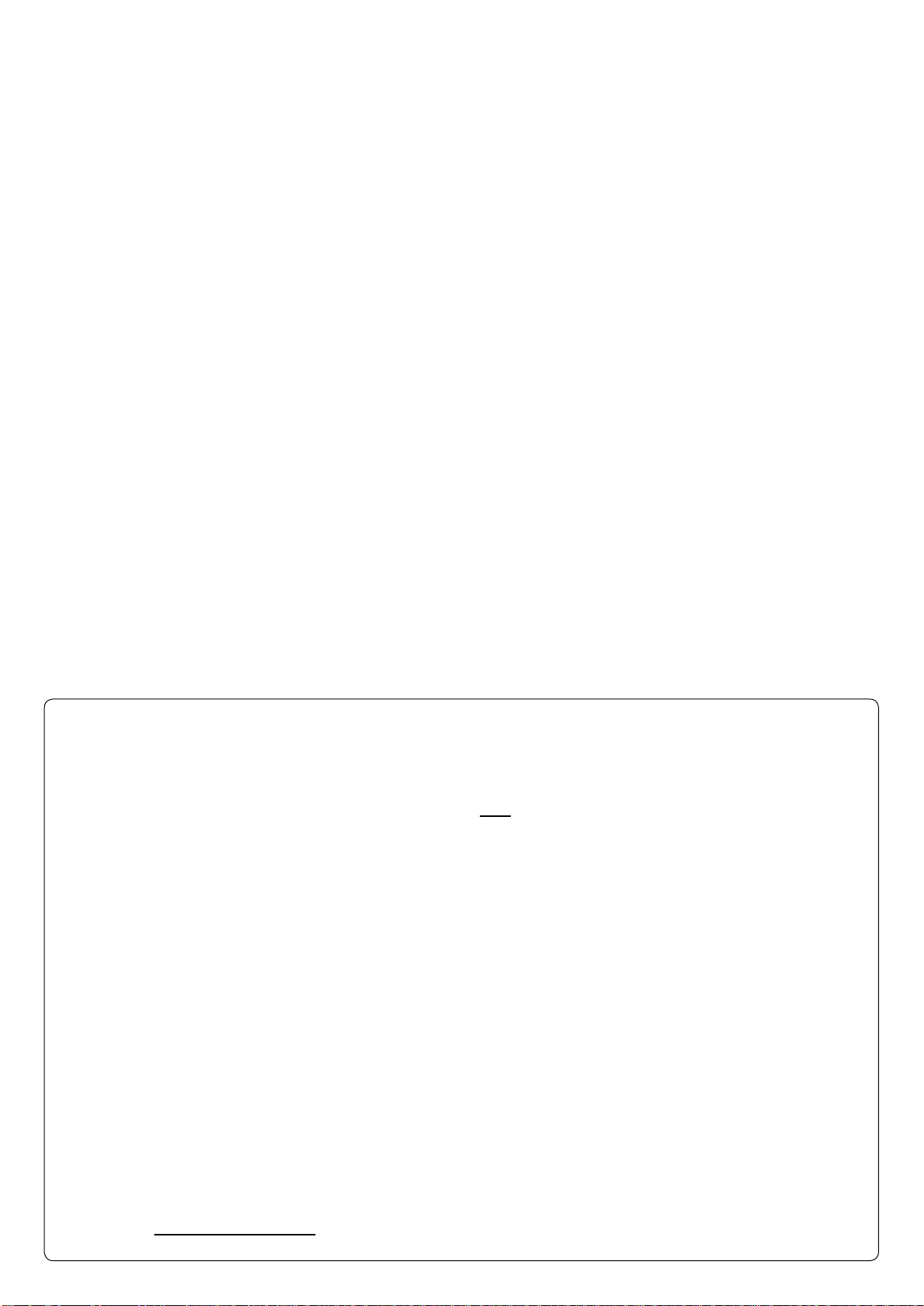
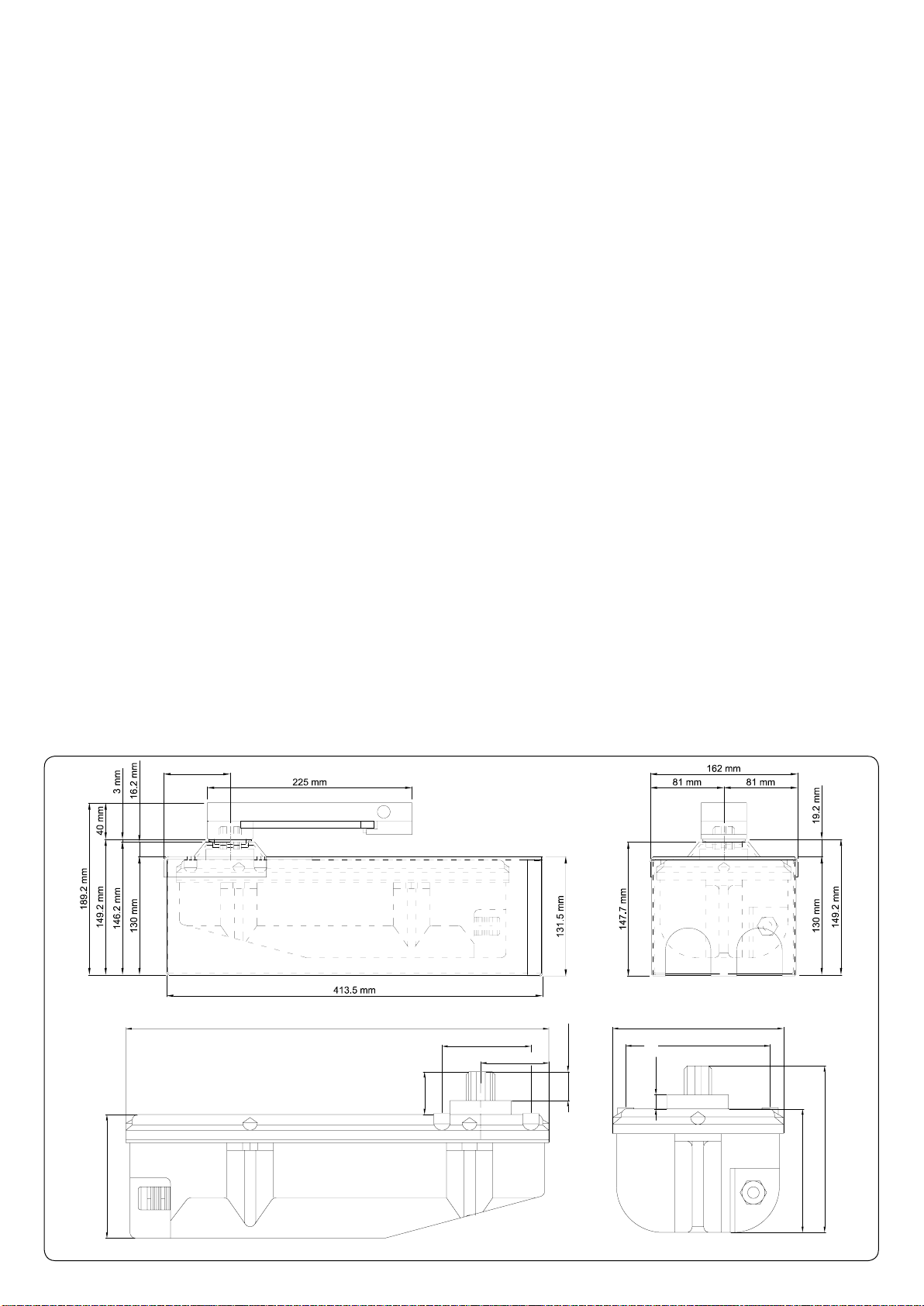
fig. 1
107 mm
30,2 mm
18 mm
12,2 mm
137,2 mm
107 mm
148 mm
125 mm
77 mm
59 mm
366 mm
66 mm
R18-6
1_ CARATTERISTICHE TECNICHE DELLA SERIE R18 \ TECHNISCHE EIGENSCHAFTEN DER SERIE R18 \
TECHNICAL FEATURES OF THE R18 SERIES \ CARACTÉRISTIQUES TECHNIQUES DE LA SÉRIE R18 \
CARACTERÍSTICAS TÉCNICAS DE LA SERIE R18
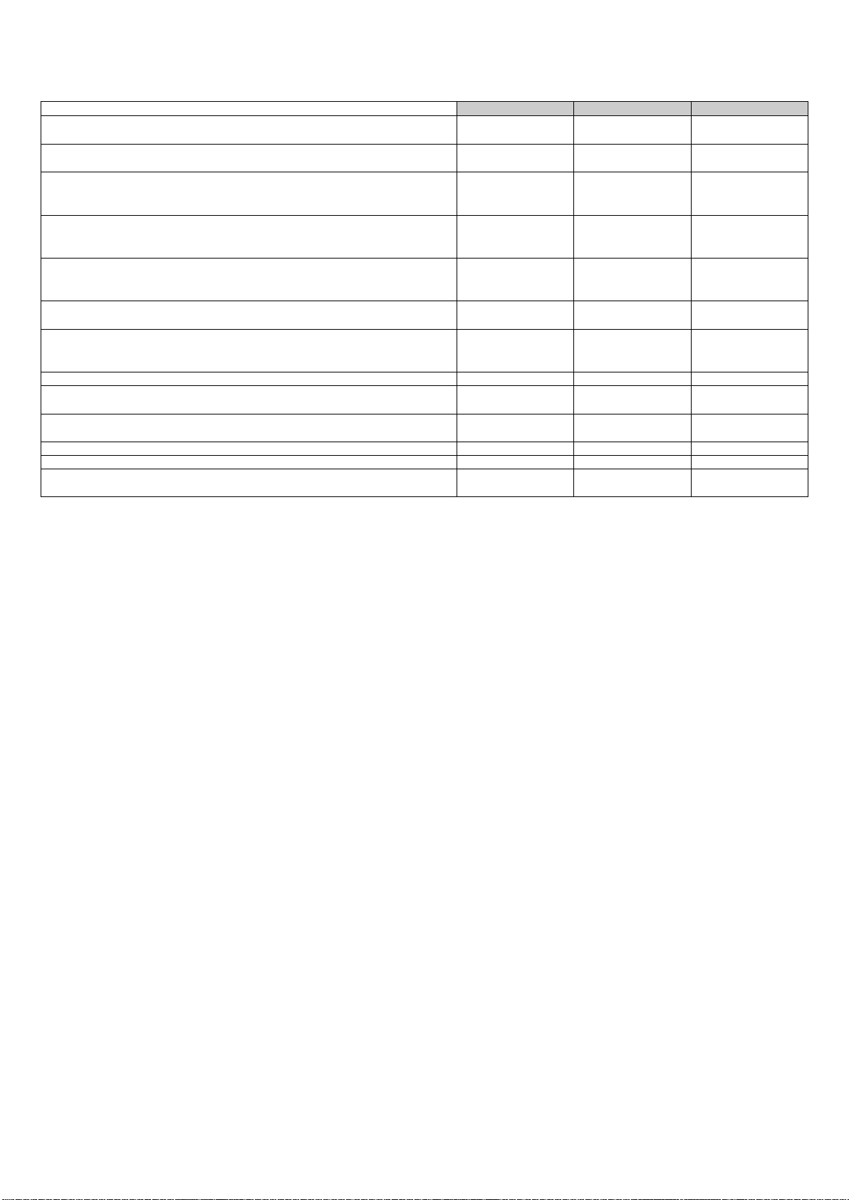
R18 R18 BENC R18 BENCVEL
Alimentazione \ Stromversorgung \ Power input \ Alimentation \
Alimentación 230 Vac 50/60 Hz 230 Vac 50/60 Hz 230 Vac 50/60 Hz
Alimentazione Motore \ Motorversorgung \ Power input to motor \
Alimentation Moteur \ Alimentación motor 230 Vac 50/60 Hz 12 Vdc 50/60 Hz 12 Vdc 50/60 Hz
Corrente assorbita a vuoto \ Aufgenommene Strom (leer) \ Absorbed
current (no load) \ Courant absorbé (à vide) \ Corriente absorbida (en
vacío) 1,6 A 0,6 A 0,8 A
Potenza assorbita a vuoto \ Aufgenommene Leistung (leer) \ Absorbed
power (no load) \ Puissance absorbée (à vide) \ Potencia absorbida (en
vacío) 300 W 15 W 20 W
Intervento di termoprotezione \ Ansprechen des Wärmeschutzes
\ Thermal protection trips at \ Intervention protection thermique \
Desconexión protección térmica 160 °C
(autoripristino) --
Velocità motore (a vuoto) \ Motordrehzahl (leer) \ Motor speed (no load) \
Vitesse moteur (à vide) \ Velocidad motor (en vacío) 900 rpm 1200 rpm 2000 rpm
Lunghezza consigliata anta* \ Empfohlene Torflügellänge* \
Recommended length of leaf* \ Longueur conseillée battant* \ Longitud
recomendada hoja* 1,8 mt. 1,8 mt. 1,2 mt.
Corsa utile \ Arbeitshub \ Useful travel \ Course utile \ Carrera útil 360° 360° 360°
Tempo corsa 90° (a vuoto) \ 90° travel time (no load) \ Laufzeit, 90° (ohne
Last) \ Temps de course 90° (à vide) \ Tiempo recorrido 90°(en vacío)
21” 13” 9”
Temperatura di esercizio \ Betriebstemperatur \ Operating temperature \
Température de fonctionnement \ Temperatura de servicio Da –20 °C a +70 °C Da –20 °C a +70 °C Da –20 °C a +70 °C
Peso \ Gewicht \ Weight \ Poids \ Peso 8 Kg 7,2 Kg 7,2 Kg
IP Motore \ Schutzart des Motor (IP) \ Motor IP \ IP Moteur \ IP Motor IP 67 IP 67 IP 67
Ciclo di lavoro \ Arbeitzzyklus \ Work cycle \ Cycle de travail \ Ciclo de
trabajo 26% 100% 100%
I - * L’anta può essere più lunga di 1,8 m ma non deve superare il peso di 200 Kg. Per lunghezze superiori a 1,8 m, non è garantito
il funzionamento.
D - * Der Flügel kann länger als 1,8 m sein, er darf aber nicht mehr als 200 kg wiegen. Im Falle von Längen über 1,8 m wird der
Betrieb nicht garantiert.
GB - * The leaf may be wider than 1.8 m but must not weigh over 200 Kg. Correct operation is not guaranteed for leaf widths greater
than 1.8 m.
F - * Le battant peut mesurer plus d’1,8 m de long mais il ne doit pas dépasser 200 Kg. Pour les longueurs supérieures à 1,8 m, le
fonctionnement n’est pas garanti.
E - * La hoja puede tener una longitud superior a los 1,8 m pero no puede superar los 200 Kg de peso. Para longitudes superiores
a los 1,8 m, no se garantiza el funcionamiento.
I - N.B.: In presenza di vento, per l’installazione su cancelli ad ante battenti cieche, non è garantito il funzionamento.
GB - N.B.: For The installation of blank swing gates, functioning cannot be gua-ranteed in the presence of wind.
D - N.B.: Bei Wind wird für die Installation an durchgehenden Flügel-toren der Betrieb nicht garantiert.
F - N.B.: En présence de vent, en cas d’installation sur des portails avec portes battantes pleines, le fonctionnement n’est
pas garanti.
E - N.B.: En presencia de viento, para la instalación en cancelas de hojas batientes cie-gas, no se garantiza el
funcionamiento.

R18-7
2_ MATERIALI PER L’INSTALLAZIONE \ INSTALLATIONSMATERIALIEN \ INSTALLATION MATERIAL \
MATÉRIAUX POUR L’INSTALLATION \ MATERIALES PARA LA INSTALACIÓN
1) Art. S-700SR40031: supporto per sblocco manuale
2) Art. S-700SR18B20: leva guida anta
3) Art. S-700CFR18B3: bronzina
4) Art. S-700CFR18B: cassa di fondazione
5) Art. S-700CFR18B1: coperchio cassa di fondazione
6) Art. P-650R18/R18BENC: gruppo motoriduttore
R18/R18BENC
7) Art. M-V100008025: vite zincata M8 x 35
8) Art. S-700SR40034: leva azionamento sblocco
manuale
1) Art. S-700SR40031: Halterung für manuelle
Entriegelung
2) Art. S-700SR18B20: Torflügel-Führungshebel
3) Art. S-700CFR18B3: Bronzelager
4) Art. S-700CFR18B: Fundamentkasten
5) Art. S-700CFR18B1: Deckel für Fundamentkasten
6) Art. P-650R18/R18BENC: Getriebemotor R18/
R18BENC
7) Art. M-V100008025: verzinkte Schraube M8 x 35
8) Art. S-700SR40034: Betätigungshebel der
manuellen Entriegelung
1) Art. S-700SR40031: support for manual release
device
2) Art. S-700SR18B20: leaf guide lever
3) Art. S-700CFR18B3: bushing
4) Art. S-700CFR18B: foundation box
5) Art. S-700CFR18B1: foundation box cover
6) Art. P-650R18/R18BENC: gear motor assembly
R18/R18BENC
7) Art. M-V100008025: galvanised screw M8 x 35
8) Art. S-700SR40034: lever for manual release device
1) Art. S-700SR40031 : support pour déblocage
manuel
2) Art. S-700SR18B20 : levier de guidage battant
3) Art. S-700CFR18B3 : coussinet en bronze
4) Art. S-700CFR18B : caisse de fondation
5) Art. S-700CFR18B1 : couvercle caisse de fondation
6) Art. P-650R18/R18BENC : groupe opérateur R18/
R18BENC
7) Art. M-V100008025 : vis zinguée M8 x 35
8) Art. S-700SR40034 : levier d’actionnement
déblocage manuel
1) Art. S-700SR40031: soporte para desbloqueo
manual
2) Art. S-700SR18B20: palanca guía hoja
3) Art. S-700CFR18B3: cojinete
4) Art. S-700CFR18B: caja de cimentación
5) Art. S-700CFR18B1: tapa caja de cimentación
6) Art. P-650R18/R18BENC: grupo motorreductor R18/
R18BENC
7) Art. M-V100008025: tornillo galvanizado M8 x 35
8) Art. S-700SR40034: palanca accionamiento
desbloqueo manual
fig. 2
3
1
7
4
8
6
I - Gruppo motoriduttore sprovvisto di frizione meccanica. Usare esclusivamente centraline di comando con frizione elettrica.
D - Der Getriebemotor ist ohne mechanische Kupplung. Ausschließlich Steuerzentralen mit elektrischer Kupplung verwenden.
GB - The gear motor is not fitted with a mechanical clutch. Only use control units with electric clutches.
F - Groupe motoréducteur dépourvu d’embrayage mécanique. Utiliser exclusivement des logiques de commande avec embrayage
électrique.
E - Grupo motorreductor sin embrague mecánico. Use exclusivamente centralitas de mando con limitador eléctrico de par de motor
por fricción.
2
5

R18-8
66
63
3_ INSTALLAZIONE CASSA DI FONDAZIONE \ INSTALLATION DES FUNDAMENTKASTENS \ INSTALLING THE
FOUNDATION BOX \ INSTALLATION CAISSE DE FONDATION \ INSTALACIÓN CAJA DE CIMENTACIÓN
fig. 3
Fondazione in cemento
Fundament aus Zement
Cement foundation
Fondation en ciment
Cimentación de cemento
Guaina passacavi
Mantel für die Kabelführung
Trought cable clamp sheath
Guaine passe-câbles
Conducto pasa cables
Tubo drenaggio acqua
Leiting für das Ablassen des Wassers
Water drainpipe
Tuyau de drenage eau
Tubo drenaje agua
fig. 4
I - a) Allineamento con l’asse.
b) Gettata in cemento.
c) Tubo di drenaggio acqua e guaina passacavi
all’esterno della gettata.
D - a) Fluchtung mit der Achse.
b) Zementschüttung.
c) Wasserdrainagerohr und Kabelmantel aus der
Zementschüttung.
GB - a) Alignment with axis.
b) Concrete casting.
c) Water drain pipe and cable sheath protruding
from casting.
F - a) Alignement dans l’axe.
b) Coulée en ciment.
c) Tuyau de drainage eau et gaine de passage des
câbles à l’extérieur de la coulée.
E - a) Alineamiento con el eje.
b) Colada de cemento.
c) Tubo de drenaje del agua y vaina pasacables en
la parte externa de la colada.
a)
c)
b)
66mm
I - È OBBLIGATORIO DRENARE L’ACQUA DALLA CASSA DI FONDAZIONE E VERIFICARNE PERIODICAMENTE IL
BUON FUNZIONAMENTO, PENA LA DECADENZA DELLA GARANZIA.
SI FA ASSOLUTO DIVIETO DI COLLEGARE IL TUBO DI DRENAGGIO DELL'ACQUA CON QUALSIASI IMPIANTO
DI SCARICO SIA CIVILE CHE INDUSTRIALE TIPO FOGNATURE (ACQUE NERE). COLLEGARSI EVENTUALMENTE
ALL'IMPIANTO DI SCARICO DI ACQUE PIOVANE (ACQUE BIANCHE).
D - DAS WASSER MUSS AUS DEM FUNDAMENTKASTEN ENTLEERT WERDEN, WEITERHIN IST DER KORREKTE
BETRIEB ZU ÜBERPRÜFEN, DA ANDERNFALLS DIE GARANTIE UNGÜLTIG WIRD.
ES IST ABSOLUT VERBOTEN, DEN DRAINAGESCHLAUCH DES WASSERSAN EINE ZIVILE ODER INDUSTRIELLE
SCHMUTZWASSER-ABFLUSSANLAGE ANZUSCHLIEßEN; DEN SCHLAUCH GGF. AN DIE REGENWASSER-
ABFLUSSANLAGE (KLARES WASSER) ANSCHLIEßEN.
GB - IT IS COMPULSORY TO DRAIN WATER FROM THE FOUNDATION BOX AND PERIODICALLY CONTROL THE
CORRECT FUNCTIONING, FAILING WHICH LAPSE OF THE GUARANTEE.
IT IS SEVERELY PROHIBITED TO CONNECT THE WATER DRAINAGE PIPE TO ANY KIND OF DRAINAGE
SYSTEM, BE IT CIVIL OR AN INDUSTRIAL SEWAGE PLANT (BLACK WATER). IF NECESSARY, THE PIPE CAN BE
CONNECTED TO A RAINWATER DRAINAGE SYSTEM (WHITE WATER).
F - IL EST OBLIGATOIRE DE DRAINER L’EAU DE LA CAISSE DE FONDATION ET D’EN VÉRIFIER PÉRIODIQUEMENT
LE BON FONCTIONNEMENT, SOUS PEINE DE DÉCHÉANCE DE LA GARANTIE.
IL EST ABSOLUMENT INTERDIT DE RACCORDER LE TUYAU DE DRAINAGE DE L’EAU À UN RÉSEAU
D’ÉVACUATION, CIVIL OU INDUSTRIEL TYPE ÉGOUT (EAUX USÉES). EFFECTUER ÉVENTUELLEMENT LE
RACCORDEMENT AU RÉSEAU PLUVIAL (EAUX ATMOSPHÉRIQUES).
E - ES OBLIGATORIO DRENAR EL AGUA DE LA CAJA DE CIMENTACIÓN Y VERIFICAR PERIÓDICAMENTE SU BUEN
FUNCIONAMIENTO, SO PENA DE LA CADUCIDAD DE LA GARANTÍA.
QUEDA TERMINANTEMENTE PROHIBIDO CONECTAR EL TUBO DE DRENAJE DEL AGUA CON CUALQUIER
INSTALACIÓN DE DESCARGA, TANTO CIVIL COMO INDUSTRIAL, DE TIPO ALCANTARILLADO (AGUAS NEGRAS).
CONÉCTESE EVENTUALMENTE A LA INSTALACIÓN DE DESCARGA DE AGUAS PLUVIALES (AGUAS BLANCAS).

R18-9
4_ INSERIMENTO MOTORIDUTTORE ED AGGANCIO DELL’ANTA \ EINBAU DES GETRIEBEMOTORS UND
ANHÄNGEN DES FLÜGELS \ INSTALLING THE GEAR MOTORANDATTACHING IT TO THE GATE \ INSERTION
DU MOTORÉDUCTEUR ET FIXATION DU BATTANT \ INTRODUCCIÓN DEL MOTORREDUCTOR Y ENGANCHE
DE LA HOJA
I - A= anta cancello
B= supporto con sblocco manuale
C= bronzina
D= coperchio cassa di fondazione
E= nr.4 viti M8 x 25 per ancoraggio motoriduttore alla cassa
di fondazione
F= cassa di fondazione
G= motoriduttore
H= leva azionamento sblocco manuale
D - A= Torflügel
B= Halterung mit manueller Entriegelung
C= Bronzebuchse
D= Fundamentkastenabdecklung
E= 4 Schrauben M8 x 35 für die Verankerung des Getrie-
bemotors am Fundamentkasten
F= Fundamentkasten
G= Getriebemotor
H= Betätigungshebel der manuellen Entriegelung
fig. 5
I - SALDAREACCURATAMENTE IL SUPPORTO B CON IL
SUPPORTO A
D - DIE HALTERUNG B SORGFÄLTIG AN DEM FLÜGEL A
ANSCHWEIßEN
GB - WELD SUPPORT B TO GATE AACCURATELY
F - SOUDER SOIGNEUSEMENT LE SUPPORT B AU
BATTANT A
E - SOLDAR CON MUCHO CUIDADO EL SOPORTE B EN
LA HOJA DE LA PUERTA A
B
A
D
C
F
E
H
G
GB - A= wing of gate
B= support with manual release devi-
ce
C= bush
D= foundation box cover
E= 4 M8 x 35 screws for securing the
gear motor to the foundation box
F= foundation box
G= gear motor
H= lever for manual release device
F - A= battant du portail
B= support avec déblocage manuel
C= coussinet en bronze
D= couvercle caisse de fondation
E= 4 vis M8 x 35 pour fixation
motoréducteur à la caisse de fon-
dation
F= caisse de fondation
G= motoréducteur
H= levier d’actionnement déblocage
manuel
E - A= hoja de la cancela
B= soporte con desbloqueo manual
C= cojinete
D= tapa caja de cimentación
E= 4 tornillos M8 x 35 para sujetar
el motorreductor en la caja de ci-
mentación
F= caja de cimentación
G= motorreductor
H= palanca accionamiento
desbloqueo manual

R18-10
5_ COLLEGAMENTO ELETTRICO AL MOTORE \ ELEKTRISCHER ANSCHLUSS AM MOTOR \ ELECTRICAL
CONNECTIONS TO THE MOTOR \ BRANCHEMENT ÉLECTRIQUE AU MOTEUR \ CONEXIÓN ELÉCTRICA AL
MOTOR
I - La distanza massima tra la centralina e il motore non deve superare i 10 - 12 mt.
Usare cavi di sezione adeguata alla potenza del motore, rispettando la vigente normativa (per R18BENC usare i cavi consigliati
dall’azienda - cod. -03000010CO).
Impianto 230 Vac (R18):
- per uno/due motori, collegare una centralina tipo D755M o versione più recente (vedi relativo manuale istruzioni per i
collegamenti);
- conduttori di fase del motore (sez.1,5 mm²); conduttore giallo-verde=massa; conduttore blu o grigio=comune; conduttore
nero= fase; conduttore marrone=fase. In prossimità della scheda collegare il condensatore in dotazione in parallelo alle due
fasi del motore.
Impianto12 Vdc (R18BENC - R18BENCVEL):
- per un motore collegare una centralina tipo MEC1000 o verisone più recente (vedi relativo manuale istruzioni per i
collegamenti);
- per due motori collegare una centralina tipo MEC2000 o verisone più recente (vedi relativo manuale istruzioni per i
collegamenti);
Fili encoder: bianco, marrone, blu (sez. 0,5 mm²);
Fili motore: nero, rosso sez.(2,5 mm²);
Verificare che ad una manovra di apertura corrisponda la manovra desiderata; in caso contrario invertire la posizione dei fili
nero-rosso.
Per i collegamenti alla scheda di comando vedere il manuale di istruzioni.
Si consiglia di installare la centralina al riparo dagli agenti atmosferici o di usare la cupolina fornita dall’azienda (cod. M-
030DL00000).
Non fare passare cavi di potenza assieme ai cavi motore. Scegliere in ogni caso i percorsi più brevi per le linee dei cavi. Si
consiglia poi di prevedere nell’impianto un interruttore generale, fuori della portata di persone inadatte, che consenta di togliere
l’alimentazione al motoriduttore in caso di manutenzione o in caso di un prolungato inutilizzo.
N.B. SI FA ASSOLUTO DIVIETO DI ESEGUIRE QUALSIASI TIPO DI COLLEGAMENTO SOTTO TRACCIA (ALL’INTERNO
DELLA CASSA DI FONDAZIONE O A LIVELLO DELLE TUBAZIONI).
Avvertenze:
- È compito dell’installatore dotare l’impianto di tutti gli accorgimenti necessari ad un suo corretto e funzionale utilizzo,
dotandolo inoltre di tutti quei dispositivi di sicurezza e/o segnalazione necessari al fine di portare a Norma l’impianto
di automazione.
- Il motoriduttore non è previsto per un impiego sommerso prolungato e come indicato nei dati tecnici ha un grado di
protezione IP 67; si consiglia pertanto di drenare correttamente la cassa di fondazione mediante dei tubi inseriti negli
appositi fori.
D - Der Höchstabstand zwischen Steuerung und Motor darf nicht über 10 - 12 m.
Kabel mit einem für die Motorleistung geeigneten Querschnitt benutzen und die gültige Vorschrift einhalten (für R18BENC die von
der Herstellerfirma empfohlenen Kabel verwenden – Code 03000010CO).
230 Vac Anlage (R18):
- für einen/zwei Motoren, eine Steuerung desTyps D755M oder eine neuereAusführung anschließen (für die Anschlüsse siehe
die jeweilige Anleitung);
- Phasenleiter des Motors (Querschn. 1,5 mm²); gelb-grüner Leiter=Masse; blauer oder grauer Leiter=gemein; schwarzer
Leiter=Phase; brauner Leiter=Phase. Den mitgelieferten Kondensator in der Nähe der Steuerkarte mit den zwei Phasen des
Motors parallel schalten.
12 Vdc Anlage (R18BENC - R18BENCVEL):
- für einen Motor, eine Steuerung des Typs MEC1000 oder eine neuere Ausführung anschließen (für die Anschlüsse siehe die
jeweilige Anleitung);
- für zwei Motoren, eine Steuerung desTyps MEC2000 oder eine neuereAusführung anschließen (für die Anschlüsse siehe die
jeweilige Anleitung);
Encoderdrähte weiß, braun, blau (Querschn. 0,5 mm²);
Motordrähte: schwarz, rot (Querschn. 2,5 mm²);
Prüfen, dass einem Öffnungsbefehl die gewünschte Bewegung folgt, andernfalls die Stellung der Drähte schwarz und rot
umkehren.
Für die Anschlüsse an der Steuerkarte wird auf die Anleitung verwiesen.
Die Steuerung vor Witterung geschützt installieren oder die vom Hersteller gelieferte Haube benutzen (Code M-
030DL00000).
Leistungskabel nicht zusammen mit Motorkabeln durchführen. Für die Kabellinien, auf jeden Fall die kürzesten Strecken wählen.
In der Anlage einen Hauptschalter außerhalb der Reichweite Unzuständiger vorsehen, mit dem die Stromversorgung zum
Getriebemotor im Falle von Wartung oder längerem Stillstand abgeschaltet werden kann.
Bitte bemerken: ES IST ABSOLUT VERBOTEN, UNTERIRDISCHE ANSCHLÜSSE (IM FUNDAMENTKASTEN) ODER AUF
HÖHE DER LEITUNGEN AUSZUFÜHREN.
Hinweise:
- Es ist Aufgabe des Installateurs, die Anlage mit allen Vorrichtungen auszustatten, die für ihren korrekten und
funktionellen Gebrauch notwendig sind, weiterhin muss sie mit allen Sicherheits- und/oder Warnvorrichtungen
ausgestattet werden, die für eine normgerechte Gestaltung der Automatisierung erforderlich sind.
- DerGetriebemotor ist für Unterwasseranwendungen nicht geeignet und hat, wie in den technischen Daten angegeben,
Schutzart IP 67; es wird daher empfohlen, das Wasser mit Hilfe der Schläuche, die in die dazu vorgesehenen
Bohrungen eingefügt worden sind, korrekt aus dem Fundamentkasten abfließen zu lassen.
GB - The distance between the control unit and the motor must not exceed 10 - 12 m.
Use cables with a suitable cross-section for the power of the motor in compliance with current standards (for R18BENC use the
cables recommended by the company - code -03000010CO).
230Vac system (R18):
- for one/two motors, connect a D755M control unit or a more recent version (see the relative instructions manual for
connections);
- motor phase conductors (sect. 1.5 mm²); yellow-green conductor=earth; blue or grey conductor=common; black
conductor=phase; brown conductor=phase. Connect the supplied condenser near the board in parallel to the two motor
phases.
12Vdc system (R18BENC - R18BENCVEL):
- for one motor, connect an MEC1000 control unit or a more recent version (see the relative instructions manual for
connections);

R18-11
- for two motors, connect an MEC2000 control unit or a more recent version (see the relative instructions manual for
connections);
Encoder wires: white, brown, blue (sect. 0.5 mm²);
Motor wires: black, red sect. (2.5 mm²);
Check that the opening command actually opens the gate; if not, invert the position of the red and black wires.
To make connections to the control board, please consult the instructions manual.
Install the control unit in a sheltered position or use the canopy supplied by the company (cod. M-030DL00000).
Do not pass the power cables together with the motor cables. Always choose the shortest routes for the cable lines. A general
switch should be fitted on the system, out of reach of unauthorised people, to allow power to be disconnected from the gearmotor
for maintenance purposes or if it is not used for a long period.
N.B. IT IS STRICTLY FORBIDDEN TO MAKE ANY UNDERGROUND CONNECTIONS (INSIDE THE FOUNDATION BOX OR
AT TUBES LEVEL).
Warnings:
- The fitter is responsible for ensuring the system can be used correctly and functionally. He must also provide it with
all the safety devices and/or signals required to ensure it complies with current law.
- The gearmotor is not designed for extended submersed use and, as indicated in the technical specifications, has
an IP 67 protection level; the foundation box should therefore be correctly drained by inserting tubes in the relative
holes.
F - La distance maximum entre la logique de commande et le moteur ne doit pas dépasser 10 - 12 m.
Utiliser des câbles de section adaptée à la puissance du moteur, en respectant les normes en vigueur (pour R18BENC utiliser les
câbles conseillés par le constructeur - code - 3000010CO).
Installation 230 Vca (R18) :
- pour un/deux moteurs, connecter une logique type D755M ou une version plus récente (voir manuel d’instructions
correspondant pour les connexions) ;
- conducteurs de phase du moteur (section 1,5 mm²) ; conducteur jaune-vert = masse; conducteur bleu ou gris = commun ;
conducteur noir = phase; conducteur brun = phase. À proximité de la carte connecter le condensateur fourni en parallèle aux
deux phases du moteur.
Installation 12 Vcc (R18BENC - R18BENCVEL) :
- pour un moteur connecter une logique type MEC1000 ou une version plus récente (voir manuel d’instructions correspondant
pour les connexions) ;
- pourdeux moteurs connecterunelogiquetypeMEC2000 ou uneversionplusrécente(voir manuel d’instructionscorrespondant
pour les connexions) ;
Fils encodeur : blanc, brun, bleu (section 0,5 mm²);
Fils moteur : noir, rouge section(2,5 mm²);
Vérifier qu’à une commande d’ouverture correspond la manœuvre désirée ; en cas contraire inverser la position des fils noir-
rouge.
Pour les connexions à la carte de commande voir le manuel d’instructions.
Il est conseillé d’installer la logique de commande à l’abri des agents atmosphériques ou d’utiliser le petit auvent fourni par le
constructeur (code M-030DL00000).
Ne pas faire passer les câbles de puissance avec les câbles moteur. Choisir dans tous les cas les parcours les plus brefs pour les
lignes des câbles. Il est conseillé de prévoir dans l’installation un interrupteur général, hors de portée des personnes inadaptées,
qui permette de couper l’alimentation de l’opérateur en cas de maintenance ou d’inutilisation prolongée.
N.B. IL EST ABSOLUMENT INTERDIT D’EFFECTUER N’IMPORTE QUEL TYPE DE CONNEXION ENTERRÉE (À
L’INTÉRIEUR DE LA CAISSE DE FONDATION OU AU NIVEAU DES CONDUITS).
Avertissements:
- L’installateur est tenu de prévoir dans l’installation toutes les mesures nécessaires pour une utilisation correcte
et fonctionnelle, en la dotant en outre de tous les dispositifs de sécurité et/ou signalisations nécessaires afin que
l’automatisme soit conforme aux normes.
- L’opérateur n’est pas prévu pour une application immergée prolongé et comme cela est indiqué dans les
caractéristiques techniques, il a un degré de protection IP 67 ; il est conseillé par conséquent de drainer correctement
la caisse de fondation en introduisant des tuyaux dans les trous prévus à cet effet.
E - La distancia máxima entre la centralina y el motor no puede superar los 10 - 12 m.
Utilice cables de sección adecuada a la potencia del motor, respetando la normativa vigente (en el R18BENC utilice los cables
que aconseja la empresa - cód. -03000010CO).
Instalación 230 Vac (R18):
- para uno/dos motores, conecte una centralina del tipo D755M o una versión más reciente (véase el manual de instrucciones
correspondiente para las conexiones);
- conductores de fase del motor (sec. 1,5 mm²); conductor amarillo-verde=masa; conductor azul o gris=común; conductor
negro=fase; conductor marrón=fase. Conecte cerca de la tarjeta el condensador presente en el equipamiento de base en
paralelo a las dos fases del motor.
Instalación 12 Vdc (R18BENC - R18BENCVEL):
- para un motor conecte una centralina del tipo MEC1000 o una versión más reciente (véase el manual de instrucciones
correspondiente para las conexiones);
- para dos motores conecte una centralina del tipo MEC2000 o una versión más reciente (véase el manual de instrucciones
correspondiente para las conexiones);
Hilos codificador: blanco, marrón, azul (sec. 0,5 mm²);
Hilos motor: negro, rojo sec.(2,5 mm²);
Verifique que a una maniobra de apertura corresponda la maniobra deseada; en caso contrario invierta la posición de los hilos
negro-rojo.
Para las conexiones a la tarjeta de mandos véase el manual de instrucciones.
Le aconsejamos que instale la centralina en un lugar protegido de los agentes atmosféricos o que utilice la pequeña cúpula
que suministra la empresa (cód. M-030DL00000).
No pase cables de potencia junto con los cables del motor. Establezca los recorridos más cortos para las líneas de los cables.
Se aconseja prever en la instalación un interruptor general, fuera del alcance de personas incapacitadas, que permita cortar la
alimentación al motorreductor en el caso de mantenimiento o de inactividad prolongada.
N.B. ESTÁ TERMINANTEMENTE PROHIBIDO EJECUTAR CUALQUIER TIPO DE CONEXIÓN BAJO TIERRA (EN EL
INTERIOR DE LA CAJA DE CIMENTACIÓN O AL NIVEL DE LAS TUBERÍAS).
Advertencias
- El instalador tiene la tarea de equipar la instalación con todos los accesorios necesarios para un uso correcto y
funcional, equipándola además con todos los dispositivos de seguridad o de señalización necesarios para que la
automatización respete las diferentes Normas.
- El motorreductor no está previsto para ser sumergido por mucho tiempo y, tal como indicado en los datos técnicos,
tiene un grado de protección IP 67; por lo tanto, se aconseja desaguar correctamente la caja de cimentación con
tubos introducidos en los taladros correspondientes.

R18-12
I - • Togliere il tappo come da figura 6.
• Inserire la chiave di sblocco nella propria sede e ruotare come da
figura 6.
L’estrazione della chiave provoca il riaggancio dell’anta appena essa
sarà allineata al motoriduttore .
Richiudere il tappo una volta tolta la chiave.
D - • Den Verschluss gemäß Abbildung 6 entfernen.
• Den Schlüssel in das Schloss stecken und wie auf Abbildung 6
drehen.
Das Abziehen des Schlüssels verursacht das Wiederschließen des
Flügels, sobald dieser zum Getriebemotor ausgerichet ist.
Den Stopfen wieder schließen, nachdem der Schlüssel gezogen ist.
GB - • Remove the cap as shown in figure 6.
• Fit the release key into the lock and turn as shown in figure 6.
When the key is removed the gate will be attached once more as soon
as it realigns with the gear motor.
Put the cap back on after removing the key.
F - • Enlever le bouchon comme sur la figure 6.
• Introduire la clé de débrayage dans le trou prévu à cet effet et
tourner comme sur la fig. 6
L’extraction de la clé provoque le réenclenchement du battant dès que
celui-ci sera aligné au motoréducteur.
Refermer le bouchon après avoir enlevé la clé.
E - • Sacar el tapón tal como muestra la figura 6.
• Introduzca la llave de desbloqueo en la cerradura y gire como
muestra la figura 6.
Al quitar la llave se provoca el reenganche de la hoja tan pronto como ésta esté alineada con el motorreductor.
Vuelva a cerrar el tapón cuando haya sacado la llave.
fig. 6
6_ USO DELLO SBLOCCO MANUALE \ VERWENDUNG DER MANUELLEN ENTRIEGELUNG \ USING THE
MANUAL RELEASE DEVICE \ UTILISATION DU DÉBLOCAGE MANUEL \ UTILIZACIÓN DEL DESBLOQUEO
MANUAL
7_ RACCOMANDAZIONI DI CARATTERE GENERALE \ ALLGEMEINE EMPFEHLUNGEN \ GENERAL ADVICE \
RECOMMANDATIONS DE CARACTÈRE GÉNÉRAL \ RECOMENDACIONES DE CARACTER GENERAL
I - • Integrare la sicurezza del portone conformemente alla Normativa vigente (prEN 13241).
Nota: per una completa sicurezza si fa obbligo di installare, se non presenti, i fermi meccanici (battenti a pavimento) con
tappo in gomma in apertura e in chiusura, come mostrato nelle figg. 7-8-9.
• Scegliere percorsi brevi per i cavi e tenere separati i cavi di potenza dai cavi di comando.
• In accordo con la Normativa europea in materia di sicurezza si consiglia di inserire un interruttore esterno per poter togliere
l’alimentazione in caso di manutenzione del portone.
• Non eseguire per nessuna ragione qualsiasi tipo di collegamento elettrico sotto traccia (all’interno della cassa di
fondazione o nelle tubazioni).
• Verificare che ogni dispositivo installato sia efficiente ed efficace.
• Affiggere cartelli facilmente leggibili che informino della presenza del portone motorizzato.
D - • Die Sicherheit des Tors gemäß den gültigen Vorschriften integrieren (prEN 13241).
BITTE BEMERKEN: für höchste Sicherheit ist die Installation der mechanischen Bodenendanschläge im Auf und Zu mit
Gummistopfen Pflicht, wie in Abbildungen 7-8-9 gezeigt.
• Die kürzesten Strecken für die Kabel wählen und die Leistungskabel von den Steuerkabeln getrennt halten.
• In Vereinbarung mit den europäischen Sicherheitsvorschriften wird empfohlen, einen externen Schalter zu installieren, damit
die Versorgung im Falle von Wartung des Tors abgeschaltet werden kann.
•Es ist absolut verboten, unterirdische elektrische Anschlüsse (im Fundamentkasten oder auf Höhe der Leitungen)
auszuführen.
• Prüfen, ob jede einzelne installierte Vorrichtung effizient und wirksam ist.
• Gut leserliche Schilder anbringen, die über das Vorhandensein des motorbetriebenen Tors informieren.
GB - • Integrate door safety to achieve compliance with current laws (prEN 13241).
Note: for complete safety, the mechanical stops with rubber cap (floor stops) must be fitted in opening and closing of
the gate, as shown in figg 7-8-9.
• Choose the short routes for the cables and keep power cables separate from control cables.
• In compliance with European safety standards, fit an outdoor switch in order to turn off the power supply when servicing the
door.
•Never make any underground electrical connections (inside the foundation box or at the tubes level).
• Make sure that each installed device is in perfect working order.
• Put up easy-to-read signs informing people that the door is powered.
F - • Intégrer la sécurité du portail conformément à la norme en vigueur (prEN 13241).
Note : pour une sécurité complète, il est obligatoire d’installer, s’il n’y en a pas, les arrêts mécaniques (butées au sol)
avec bouchon en caoutchouc en ouverture et fermeture, comme indiqué sur les illustrations 7-8-9.
• Choisir des parcours brefs pour les câbles et maintenir les câbles de puissance séparés des câbles de commande.
• Conformément à la réglementation européenne en matière de sécurité, il est conseillé d’insérer un interrupteur extérieur pour
pouvoir couper l’alimentation en cas de maintenance du portail.
•N’effectuer sous aucun prétexte des connexions électriques enterrées, quelles qu’elles soient (à l’intérieur de la
caisse de fondation ou au niveau des conduits).
R18-1
ISTRUZIONI ED AVVERTENZE DESTINATE ALL’UTILIZZATORE DELL’AUTOMAZIONE
COMPLIMENTI per aver scelto per la vostra automazione un prodotto Tau!
Tau S.r.l. produce componenti per l’automazione di cancelli, porte, barriere, serramenti: motoriduttori, centrali di comando, radiocomandi, lampeggianti,
fotocellule e accessori.
I prodotti Tau sono realizzati solo con materiali e lavorazioni di qualità e, come azienda, siamo alla costante ricerca di soluzioni innovative che
semplifichino sempre più l’utilizzo delle nostre apparecchiature, curate sotto ogni aspetto (tecnico, estetico ed ergonomico): nella grande gamma Tau il
vostro installatore può scegliere il prodotto che meglio soddisfa le vostre esigenze.
Tau però non produce la vostra automazione che, invece, è il risultato di un’opera di analisi, di valutazione, di scelta dei materiali e realizzazione
dell’impianto eseguita dal vostro installatore di fiducia.
Ogni automazione, pertanto, è unica e solo il vostro installatore può eseguire un impianto secondo le vostre esigenze (in quanto dotato dell’esperienza
e della professionalità necessarie), sicuro ed affidabile nel tempo; e soprattutto a regola d’arte, rispondente cioè alle normative in vigore.
Un impianto di automazione è una bella comodità, oltre che un valido sistema di sicurezza e, con poche, semplici attenzioni, è destinato a durare negli
anni.
Anche se l’automazione in vostro possesso soddisfa il livello di sicurezza richiesto dalle normative, questo non esclude l’esistenza di un “rischio residuo”,
cioè la possibilità che si possano generare situazioni di pericolo, dovute ad un utilizzo incosciente e/o errato. Per questo motivo riportiamo alcuni consigli
sui comportamenti da tenere per evitare ogni inconveniente:
- Al primo utilizzo: chiedete al vostro installatore di spiegarvi l’origine dei rischi residui e leggete il presente manuale di istruzioni ed avvertenze per
l’utilizzatore consegnatovi dall’installatore. Conservate il manuale per qualsiasi problema futuro e ricordatevi di consegnarlo ad un eventuale nuovo
proprietario dell’impianto.
- L’impianto di automazione esegue fedelmente i vostri comandi: un uso incosciente e/o improprio può divenire pericoloso. Evitate quindi di
azionare l’automazione quando nel suo raggio d’azione si trovino persone, animali e/o cose.
- NON È UN GIOCO! Fate in modo che i bambini non giochino in prossimità dell’impianto e tenete i telecomandi fuori della loro portata.
- Anomalie: ad ogni comportamento anomalo dell’impianto, togliete l’alimentazione elettrica all’automazione ed eseguite lo sblocco manuale (come
da figura). Evitate qualsiasi intervento personale e chiamate il vostro installatore: una volta sbloccato, l’impianto funzionerà manualmente come
prima dell’installazione.
- Manutenzione: per durare nel tempo e funzionare in completa sicurezza, come qualsiasi altro macchinario, l’impianto necessita di una periodica
manutenzione. Stabilite insieme al vostro installatore i tempi di tale manutenzione. Tau consiglia un intervento ogni 6 mesi per un normale uso
domestico, che può variare in funzione dell’intensità d’uso (sempre ogni 3000 cicli di lavoro).
N.B. Qualsiasi tipo di intervento (controllo, manutenzione e/o riparazione) deve essere eseguito solo da personale qualificato.
- Non modificare l’impianto, nè i relativi parametri di programmazione e di regolazione: la responsabilità è dell’installatore.
N.B. Il collaudo finale, le manutenzioni periodiche e le eventuali riparazioni devono essere documentate (negli appositi spazi) da chi le esegue
e i documenti conservati dal proprietario dell’impianto (IN CASO DI MANCATA DOCUMENTAZIONE LA GARANZIA DECADE).
- Smaltimento: al termine della vita dell’impianto assicuratevi che lo smantellamento venga eseguito da personale qualificato e che i materiali
vengano riciclati o smaltiti secondo le norme valide a livello locale.
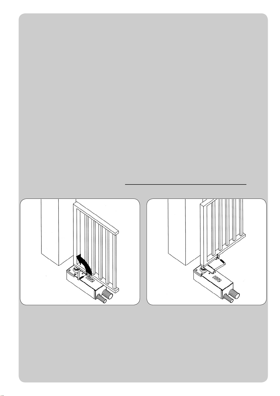
- - -- - - - - - - - - - - - - - - - - - - - - - - - - - - - - - - - - - - - - - - - - - - - - - - - - - - - - - - - - - - - - - - - - - - - - - - - - - - - - - - - - - - - - - - - - - - - - -
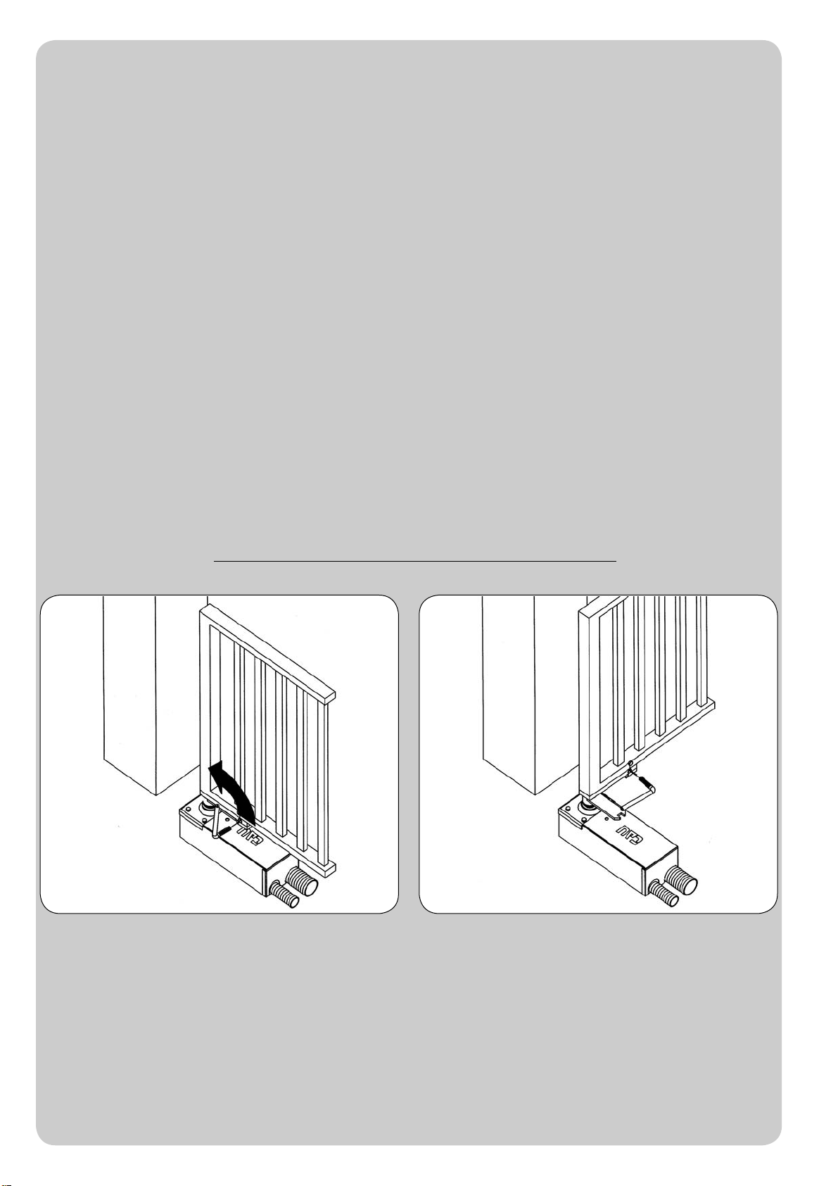
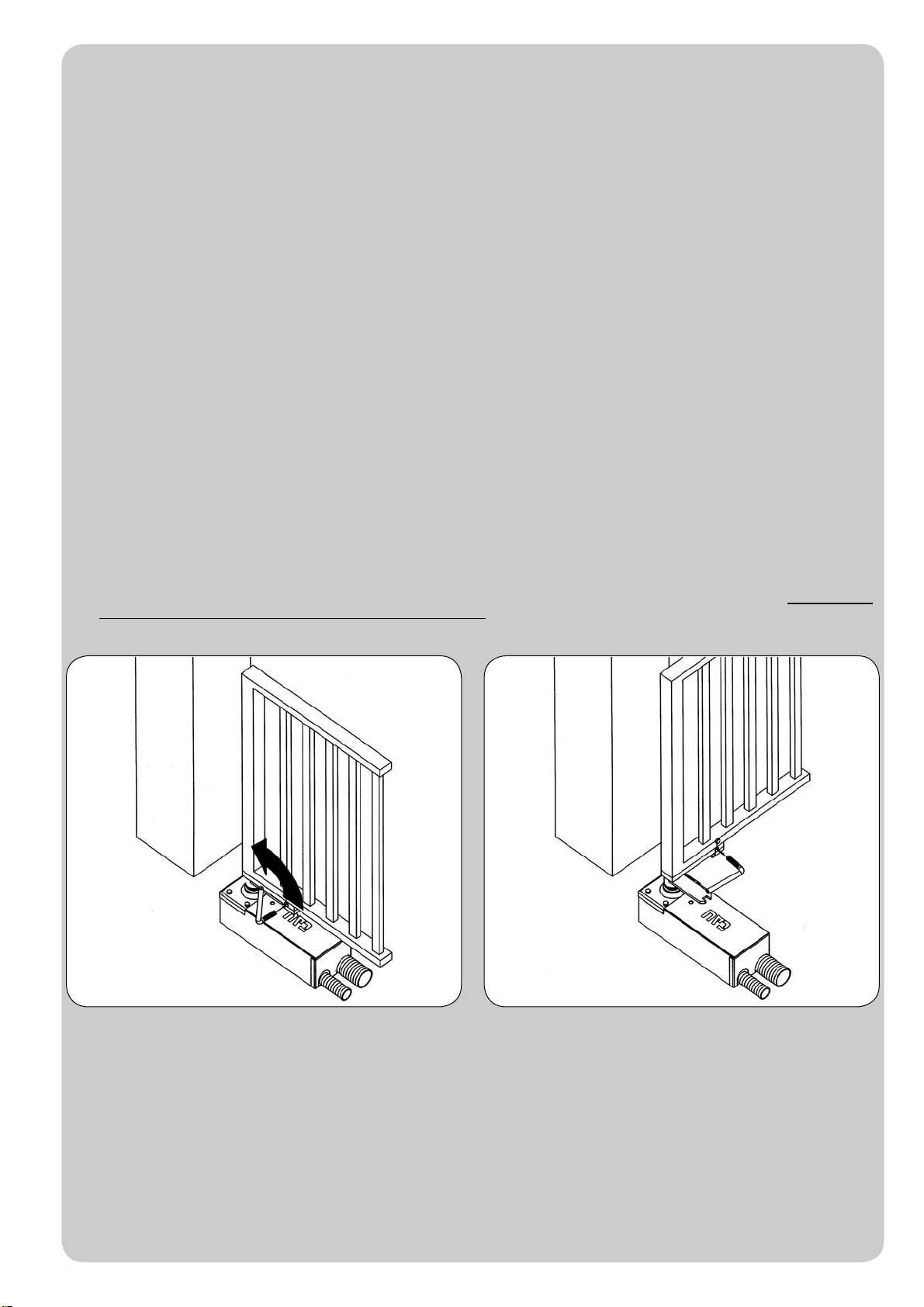
Togliere il tappo, infilare la chiave a tubo nel foro della leva del cancello e
ruotare nel senso indicato.
Quindi aprire il battente del cancello manualmente.
La manovra manuale deve essere eseguita SOLO a porta ferma e DOPO aver tolto l’alimentazione alla centrale elettrica.
Nota: se il vostro impianto è dotato di un telecomando che dopo qualche tempo vi sembra funzionare peggio, oppure non funzionare
affato, potrebbe semplicemente dipendere dall’esaurimento della pila (a seconda del tipo, possono trascorrere diversi mesi fino a 2/3
anni). Ve ne potete accorgere dal fatto che la spia di conferma della trasmissione è debole, oppure si accende solo per un breve istante.
Prima di rivolgervi all’installatore provate a scambiare la pila con quella di un altro trasmettitore eventualmente funzionante: se questa
fosse la causa dell’anomalia, sarà sufficiente sostituire la pila con un’altra dello stesso tipo.
Nel caso voleste aggiungere nella vostra casa un nuovo tipo di automazione, rivolgendovi allo stesso installatore e alla Tau vi garantirete,
oltre che la consulenza di uno specialista e i prodotti più evoluti del mercato, il migliore funzionamento e la massima compatibilità delle
automazioni.
Vi ringraziamo per aver letto queste raccomandazioni, e vi auguriamo la massima soddisfazione dal vostro nuovo impianto: per ogni tipo
di esigenza rivolgetevi con fiducia al vostro installatore.
Italiano
R18-2
Remove the plug, insert the box wrench into the gate lever and
turn in the indicated direction. Then open the leaf of the gate by hand.
The manual manoeuvre must ONLY be done with the door stopped and AFTER disconnecting power from the electrical control unit.
N.B.: if your remote control unit (if supplied) starts working badly after a time, or does not work at all, the batteries may be flat (they can last from
several months to 2/3 years depending on what type is used). This can be seen from the fact that the transmission confirmation LED gets dimmer
or only turns on for brief moments. Before contacting your fitter, try exchanging the battery with one from a good transmitter: if this is the reason
for the fault, simply replace the battery with another one of the same type.
If you wish to add a new automated system to your house, contact your fitter and we at Tau to have the advice of a specialist, the most developed
products on the market, best operation and maximum automation compatibility.
Thank you for reading these suggestions and we trust you are fully satisfied with your new system: please contact your fitter for any further
requirements.
English
INSTRUCTIONS AND WARNINGS FOR AUTOMATIC SYSTEM USERS
CONGRATULATIONS on choosing a Tau product for your automation system!
Tau S.r.l. produces components for automatic gates, doors, barriers and shutters. These include gear motors, control units, radio control devices, flashing
lights, photocells and accessories.
Tau products are exclusively made with top quality materials and processes and, as a company, we constantly research and develop innovative solutions
in order to make our equipment increasingly easier to use. We also pay great attention to all details (technology, appearance and ergonomics). The
extensive Tau range makes it possible for your fitter to choose the product which best meets your requirements.
Tau, however, does not produce your automated system as this is the outcome of a process of analysis, evaluation, choice of materials and installation
performed by your fitter.
Each automated system is unique, therefore, and only your fitter has the experience and professionalism required to create a system that is tailor-made
to your requirements, featuring long-term safety and reliability, and, above all, professionally installed and compliant with current regulations.
An automated system is handy to have as well as being a valid security system. Just a few, simple operations are required to ensure it lasts for years.
Even if your automated system satisfies regulatory safety standards, this does not eliminate “residue risks”, that is, the possibility of dangerous situations
being generated, usually due to irresponsible and/or incorrect use. For this reason we would like to give you some suggestions on how to avoid these
risks:
- Before using the system for the first time: ask your fitter to explain how residue risks can arise and read the instructions and warnings in the user
handbook that your fitter will have given you. Keep this manual for future use and, if you should ever sell your automated system, hand it over to the
new owner.
- Your automated system carries out your commands to the letter: irresponsible and/or incorrect use may cause it to become dangerous. Do not
use the system if people, animals and/or objects enter its operating area.
- IT IS NOT A TOY! Make sure children do not play near the system and keep the remote control device out of their reach.
- Faults: If you notice any abnormal behaviour, disconnect the system from the power supply immediately and perform the manual release operation
(see figure). Do not attempt to repair the door but call in your fitter: the system will operate manually as it did before installation.
- Maintenance: to ensure long life and totally safe operation, the system required routine maintenance, just like any other piece of machinery.
Establish maintenance times together with your fitter. Tau recommends a frequency of 6 months for normal domestic installations but this may vary
depending on the intensity of use (always every 3000 work cycles).
N.B.: All controls, maintenance work and/or repairs may only be carried out by qualified personnel.
- Do not modify the plant or the relative programming and adjustment parameters: your fitter will see to that.
N.B. Final testing, routine maintenance and any repairs must be documented by the fitter (in the relative spaces) and such documents kept
by the owner of the system (IF THE DOCUMENTS ARE NOT PRODUCED, THE WARRANTY WILL EXPIRE).
- Disposal: At the end of system life, make sure that it is demolished by qualified personnel and that the materials are recycled or disposed of
according to local regulations.

R18-3
Den Verschluss entfernen, den Rohrschlüssel in den Torhebel
stecken und in die angegebene Richtung drehen. Dann den Torflügel von Hand öffnen.
Die manuelle Bewegung darf AUSSCHLIESSLICH bei stehendem Tor und NACH Abschalten der Versorgung zur Steuerung ausgeführt
werden.
Anmerkung: wenn eine Fernbedienung zu Ihrer Anlage gehört, die nach einer bestimmten Zeit schlechter oder gar nicht funktioniert, sollten Sie die
Batterie kontrollieren, die ganz einfach leer sein könnte (je nach Typ, kann die Batterie mehrere Monate bis 2-3 Jahre dauern). Sie können das am
Leuchtmelder bemerken, der die Übertragung bestätigt und nur schwach oder ganz kurz aufleuchten wird. Tauschen Sie die Batterie mit der eines
anderen, funktionierenden Senders aus, bevor Sie sich an den Installateur wenden: falls die Ursache der Betriebsstörung eine leere Batterie sein sollte,
genügt es, diese mit einer anderen gleichen Typs zu ersetzen.
Falls Sie Ihrem Haus eine weitere neue Automatisierung hinzufügen wollen, werden Sie sich bei Ihrem Installateur und bei Tau neben der Beratung
eines Fachmanns die fortgeschrittensten Produkte garantieren, die es auf dem Markt gibt, mit bestem Betrieb und maximaler Kompatibiltät der
Automatisierungen.
Wir danken Ihnen, dass Sie diese Hinweise gelesen haben und wünschen Ihnen volle Zufriedenheit mit Ihrer neuenAnlage. Wenden Sie sich für jeden
Bedarf vertrauensvoll an Ihren Installateur.
Deutsch
ANWEISUNGEN UND HINWEISE FÜR DEN BENUTZER DER AUTOMATISIERUNG
WIR GRATULIEREN IHNEN zur Wahl eines Tau Produktes für IhreAutomatisierung!
Tau S.r.l. stellt Komponenten für die Automatisierung von Toren, Türen, Schranken und Fenstern her: Getriebemotoren, Steuerzentralen,
Funksteuerungen, Blinkleuchten, Fotozellen und Zubehör.
Die Tau Produkte werden nur mit Materialien und Bearbeitungen hoher Qualität hergestellt, und unsere Firma ist auf der ständigen Suche nach
innovativen Lösungen, mit denen die Benutzung unserer Apparaturen, die in jeder Hinsicht (Technik, Aussehen und Ergonomie) besonders gepflegt
sind, immer einfacher wird: unter dem großen Tau Sortiment kann Ihr Installateur das Produkt auswählen, das Ihrem Bedarf am besten entspricht.
Tau ist aber nicht der Hersteller Ihrer Automatisierung, die dagegen das Ergebnis des Werks Ihres Vertrauensinstallateurs ist, der sich mit den
notwendigen Untersuchungen und Bewertungen, der Wahl der Materialien und der Verwirklichung die Anlage beschäftigen wird.
Jede Automatisierung ist daher einzigartig und nur Ihr Installateur kann eine Anlage ausführen, die Ihrem Bedarf entspricht (er besitzt die notwendige
Erfahrung und Professionalität), die sicher und auf Zeit zuverlässig und vor allem fachgerecht ist und mit den gültigen Vorschriften übereinstimmt.
Eine Automatisierungsanlage ist etwas wirklich bequemes, aber auch ein gutes Sicherheitssystem, und mit ein paar einfachen Maßnahmen wird sie
jahrelang dauern.
Auch wenn Ihre Automatisierung dem Sicherheitsniveau entspricht, das von den Vorschriften gefordert wird, schließt dies das Vorhandensein eines
„Restrisikos” nicht aus, bzw. der Möglichkeit, dass Gefahren aufgrund eines fahrlässigen und/oder falschen Gebrauchs erzeugt werden können. Aus
diesem Grund geben wir hier einige Verhaltensweisen an, um diese möglichen Restrisiken zu vermeiden:
- Bei der ersten Benutzung: bitten Sie Ihren Installateur, Ihnen den Ursprung der Restrisiken zu erklären, und lesen Sie die vorliegenden
Anweisungen und Hinweise für den Benutzer, die Ihnen vom Installateur übergeben werden. Bewahren Sie dieAnleitung für zukünftige Probleme
auf, und übergeben Sie diese ggf. dem neuen Besitzer derAnlage.
- Die Automatisierungsanlage folgt getreu Ihren Befehlen: ein fahrlässiger und/oder unsachgemäßer Gebrauch kann gefährlich sein. Betätigen
Sie daher dieAutomatisierung nicht, wenn sich Personen, Tiere und/oder Gegenstände in ihremAktionskreis befinden.
- SIE IST KEIN SPIEL! Lassen Sie Kinder nicht in der Nähe derAnlage spielen und halten Sie die Fernbedienungen außer deren Reichweite.
- Störungen: schalten Sie bei jedem ungewöhnlichen Verhalten der Anlage die Stromversorgung zur Automatisierung ab und entriegeln Sie von
Hand (sieheAbbildung). Vermeiden Sie jeden persönlichen Eingriff und rufen Sie Ihren Installateur: nach dem Entriegeln wird dieAnlage von Hand
funktionieren, wie vor der Installation.
- Wartung: um zu dauern und ganz sicher zu funktionieren, bedarf die Anlage wie jede andere Maschine einer periodischen Wartung. Legen Sie
die Wartungszeiten zusammen mit Ihrem Installateur fest. Tau empfiehlt für den normalen Hausgebrauch eine Wartung alle 6 Monate, was je nach
Gebrauchshäufigkeit unterschiedlich sein kann (immer ungefähr 3000Arbeitszyklen).
N.B.: Eingriffe (Kontrolle, Wartung und/oder Reparatur) dürfen nur von Fachpersonal ausgeführt werden.
- Anlage und programmierte und eingestellte Parameter nicht ändern, das ist Aufgabe des Installateurs.
N.B.: Endprüfung, periodische Wartungsarbeiten und eventuelle Reparaturen müssen von dem, der sie ausführt, belegt sein (in den dazu
bestimmten Feldern); diese Unterlagen muss der Besitzer der Anlage aufbewahren (DIE GARANTIE WIRD UNGÜLTIG, FALLS DIE
DOKUMENTATION FEHLT).
- Entsorgung: stellen Sie am Ende der Lebensdauer der Anlage sicher, dass die Entsorgung durch Fachpersonal erfolgt und dass die Materialien
nach den örtlich gültigen Vorschriften recycled oder entsorgt werden.

R18-4
Enlever le bouchon, enfiler la clé à tube dans le trou du levier
du portail et tourner dans le sens indiqué. Ouvrir ensuite le portail à la main.
La manœuvre manuelle doit être exécutée UNIQUEMENT avec la porte fermée et APRÈS avoir coupé l’alimentation de l’armoire électrique.
Note : si votre installation est munie d’une télécommande qui au bout de quelques temps semble moins bien fonctionner ou ne plus fonctionner du tout,
cela peut dépendre tout simplement de la pile (suivant le type sa durée est de plusieurs mois jusqu’à 2/3 ans). Vous pouvez vous en rendre compte à
travers le fait que le voyant de confirmation de la transmission est faible ou bien, s’il ne s’allume qu’un bref instant.Avant de vous adresser à l’installateur,
essayez d’échanger la pile avec celle d’un autre émetteur qui fonctionne correctement : si la cause de l’anomalie est celle-ci, il suffira de remplacer la
pile par une autre du même type.
Si vous désirez ajouter un nouveau type d’automatisme dans votre habitation, adressez-vous au même installateur et à Tau ; en plus du conseil d’un
spécialiste, vous aurez ainsi la garantie des produits les plus évolués sur le marché, du meilleur fonctionnement et du maximum de compatibilité entre
les automatismes.
Nous vous remercions d’avoir lu ces recommandations et nous espérons que votre nouvelle installation vous donnera toute satisfaction : pour tout type
d’exigence, adressez-vous en toute confiance à votre installateur.
Français
INSTRUCTIONS ET RECOMMANDATIONS DESTINÉES À L’UTILISATEUR DE L’AUTOMATISATION
FÉLICITATIONS pour avoir choisi pour votre automatisation un produit Tau !
Tau S.r.l. produit des composants pour l’automatisation de portails, portes, barrières, volets : opérateurs, logiques de commande, radiocommandes,
clignotants, photocellules et accessoires.
Les produits Tau sont réalisés exclusivement avec des matériaux et des usinages de qualité et en tant qu’entreprise, nous sommes à la recherche
constante de solutions innovantes qui simplifient de plus en plus l’utilisation de nos appareils, soignés sur tous les plans (technique, esthétique et
ergonomique) : dans la vaste gamme Tau, votre installateur peut choisir le produit qui satisfera au mieux vos exigences.
Tau toutefois ne produit pas votre automatisation qui est, en fait, le résultat d’un travail d’analyse, d’évaluation, de choix des matériaux et de réalisation
de l’installation effectué par votre installateur de confiance.
Chaque automatisation, par conséquent, est unique et seul votre installateur peut réaliser une installation suivant vos exigences (dans la mesure où
il est doté de l’expérience et de la qualification professionnelle nécessaire), sûre et fiable dans le temps et, surtout, effectuée dans les règles de l’art,
c’est-à-dire conforme aux normes en vigueur.
Une installation d’automatisation est d’une grande commodité, en plus de représenter un système de sécurité et, avec un minimum d’attentions, elle est
destinée à durer des années.
Même si l’automatisme en votre possession satisfait le niveau de sécurité requis par les normes, cela n’exclut pas l’existence d’un “risque résiduel”,
c’est-à-dire la possibilité que des situations de danger puissent se vérifier, à cause d’une utilisation non raisonnable et/ou erronée. Pour cette raison,
nous donnons quelques conseils sur les comportements à suivre pour éviter tout inconvénient :
- À la première utilisation : demandez à votre installateur de vous expliquer l’origine des risques résiduels et lisez ce manuel d’instructions et
de recommandations pour l’utilisateur qui vous a été remis par l’installateur. Conservez le manuel pour tout problème futur et n’oubliez pas de le
remettre à l’éventuel nouveau propriétaire de l’installation.
- L’installation d’automatisation exécute fidèlement vos commandes : une utilisation non raisonnable et/ou impropre peut devenir dangereuse.
Évitez par conséquent d’actionner l’automatisme quand des personnes, des animaux ou des objets se trouvent dans son rayon d’action.
- CE N’EST PAS UN JEU ! Faites en sorte que les enfants ne jouent pas à proximité de l’installation et conservez les télécommandes hors de leur
portée.
- Anomalies: à tout comportement anormal de l’installation, coupez l’alimentation électrique de l’automatisme et effectuez le déblocage manuel
(comme sur la figure). Évitez toute intervention personnelle et contactez votre installateur : une fois débloquée, l’installation fonctionnera
manuellement, comme avant l’automatisation.
- Maintenance : pour durer dans le temps et fonctionner en toute sécurité, comme toute autre machine, l’installation a besoin d’une maintenance
périodique. Établissez avec votre installateur un plan de maintenance. Tau conseille une intervention tous les 6 mois pour un usage domestique
normal qui peut varier suivant l’intensité d’utilisation (toujours tous les 3000 cycles de travail).
N.B. N’importe quel type d’intervention (contrôle, maintenance et/ou réparation) doit être effectué uniquement par du personnel qualifié.
- Ne pas modifier l’installation ni les paramètres de programmation et de réglage : la responsabilité en incombe à l’installateur.
N.B. l’essai de fonctionnement final, les maintenances périodiques et les éventuelles réparations doivent être documentées (dans les
espaces prévus à cet effet) par qui les exécute et les documents doivent être conservés par le propriétaire de l’installation (EN CASE DE
NON-PRÉSENTATION DE LA DOCUMENTATION, LA GARANTIE N’EST PLUS VALABLE).
- Démantèlement : à la fin de la vie de l’installation, assurez-vous que le démantèlement soit effectué par du personnel qualifié et que les matériaux
soient recyclés ou mis au rebut suivant les normes en vigueur au niveau local.
R18-5
Sacar el tapón, introducir la llave tubular en el agujero de la
palanca de la cancela y girar en el sentido indicado. Entonces abra a mano la hoja de la cancela.
La maniobra manual debe efectuarse SÓLO con la puerta detenida y DESPUÉS de haber cortado la alimentación a la central eléctrica.
Nota: si su instalación está dotada de un control remoto que, transcurrido un cierto período, no funciona correctamente o deja de funcionar,
podría ser que la pila esté agotada (dura desde varios meses a 2/3 años según el modelo). Ud. se podrá dar cuenta de este inconveniente por el
hecho de que la luz del indicador de confirmación de la transmisión es débil, o bien se enciende sólo durante un breve instante. Antes de llamar
al instalador, pruebe sustituir la pila con una de otro transmisor que funcione correctamente: si el problema fuera este, sustituya la pila con otra
del mismo tipo.
Si Ud. deseara montar en su casa un nuevo tipo de automatización, contacte al mismo instalador y a Tau, así podrá tener la garantía de
un asesoramiento de un experto y los productos más modernos del mercado, el mejor funcionamiento y la máxima compatibilidad de las
automatizaciones.
Le agradecemos por haber leído estas recomendaciones y esperamos que esté satisfecho de su nueva instalación: ante cualquier exigencia,
contacte con confianza a su instalador.
Español
INSTRUCCIONES Y ADVERTENCIAS DESTINADAS AL USUARIO DE L’AUTOMATISMO
¡FELICITACIONES por haber elegido un producto TAU para su automatización!
Tau S.r.l. produce componentes para la automatización de cancelas, puertas, barreras, cerramientos, tales como: motorreductores, centrales de mando,
radiomandos, luces intermitentes, fotocélulas y accesorios.
Los productos Tau son fabricados sólo con materiales de calidad y excelentes mecanizados. Nuestra empresa busca constantemente soluciones
innovadoras que simplifiquen aún más el uso de nuestros aparatos, los que son cuidados bajo todo aspecto (técnico, estético y ergonómico): en la gran
gama Tau, su instalador puede escoger el producto que satisfaga de la mejor manera sus exigencias.
Tau no es quien escoge los componentes de su automatización, este es un trabajo de análisis, evaluación, elección de los materiales y realización de
la instalación efectuado por su instalador de confianza.
Por lo tanto, cada automatización es única y sólo su instalador puede ejecutar una instalación a medida de sus exigencias (puesto que cuenta con la
experiencia y profesionalidad necesarias), segura y fiable en el tiempo y, sobre todo, que respete las normativas vigentes.
Una instalación de automatización es una gran comodidad, además de un sistema de seguridad válido y, con un mantenimiento reducido y sencillo,
está destinada a durar por mucho tiempo.
Aunque bien su automatización satisfaga el nivel de seguridad requerido por las normativas, esto no excluye la existencia de un “riesgo residual”, es
decir, la posibilidad de que se puedan crear situaciones de peligro causadas por un uso inconsciente o incorrecto. Por dicho motivo, a continuación le
damos algunos consejos sobre cómo comportarse para evitar inconvenientes:
- La primera vez que se usa: pida a su instalador que le explique el origen de los riesgos residuales y lea este manual de instrucciones y
advertencias para el usuario entregado por el instalador. Conserve el manual por cualquier problema que pueda surgir y recuerde entregarlo a un
posible nuevo dueño de la instalación.
- La instalación de automatización ejecuta fielmente los mandos dados: un uso inconsciente o inadecuado puede ser peligroso. Por
consiguiente, no accione la automatización cuando en su radio de acción haya personas, animales o cosas.
- ¡NO ES UN JUGUETE! Trate de que los niños no jueguen cerca de la instalación y mantenga los controles remotos lejos de su alcance.
- Desperfectos: cada vez que la instalación no funcione correctamente, corte la alimentación eléctrica de la automatización y realice el desbloqueo
manual (como muestra la figura). No realice ninguna reparación y llame a su instalador: una vez desbloqueada, la instalación funcionará
manualmente como antes de montar la automatización.
- Mantenimiento: para garantizar una larga vida útil y para un funcionamiento seguro, la instalación, al igual que cualquier otra maquinaria, requiere
un mantenimiento periódico. Establezca con su instalador las frecuencias de dicho mantenimiento. Tau aconseja realizar un mantenimiento cada
6 meses para un uso residencial normal, que puede variar según la intensidad de uso (siempre cada 3000 ciclos de trabajo).
N.B. cualquier tipo de operación (control, mantenimiento o reparación) debe ser realizada sólo por personal cualificado.
- No modifique la instalación ni los parámetros de programación y regulación: la responsabilidad es del instalador.
N.B.: el ensayo final, los trabajos de mantenimiento periódico y las posibles reparaciones deben ser documentados (en los espacios
disponibles) por quien los efectúa y los documentos tienen que ser conservados por el dueño de la instalación (LA FALTA DE
DOCUMENTACIÓN DETERMINA LA CADUCIDAD DE LA GARANTÍA).
- Desguace: al final de la vida útil de la instalación, el desguace debe ser realizado por personal cualificado y los materiales deben ser reciclados o
eliminados según las normas locales vigentes.
R18-6
Data
Date
Datum
Date
Fecha
Descrizione intervento
Description of job
Beschreibung des Eingriffs
Description intervention
Descripción del trabajo
Parti sostituite
Parts replaced
Ersetzte teile
Parties remplacées
Piezas sustituidas
Firma manutentore
Fitter’s signature
Unterschrift des
Wartungsmannes
Signature réparateur
Firma del técnico
Firma utilizzatore
User’s signature
Unterschrift des
Benutzers
Signature utilisateur
Firma del usuario
R18-7
Data
Date
Datum
Date
Fecha
Descrizione intervento
Description of job
Beschreibung des Eingriffs
Description intervention
Descripción del trabajo
Parti sostituite
Parts replaced
Ersetzte teile
Parties remplacées
Piezas sustituidas
Firma manutentore
Fitter’s signature
Unterschrift des
Wartungsmannes
Signature réparateur
Firma del técnico
Firma utilizzatore
User’s signature
Unterschrift des
Benutzers
Signature utilisateur
Firma del usuario

R18-8
Data
Date
Datum
Date
Fecha
Descrizione intervento
Description of job
Beschreibung des Eingriffs
Description intervention
Descripción del trabajo
Parti sostituite
Parts replaced
Ersetzte teile
Parties remplacées
Piezas sustituidas
Firma manutentore
Fitter’s signature
Unterschrift des
Wartungsmannes
Signature réparateur
Firma del técnico
Firma utilizzatore
User’s signature
Unterschrift des
Benutzers
Signature utilisateur
Firma del usuario
- - -- - - - - - - - - - - - - - - - - - - - - - - - - - - - - - - - - - - - - - - - - - - - - - - - - - - - - - - - - - - - - - - - - - - - - - - - - - - - - - - - - - - - - - - - - - - - - -
Other manuals for R18 series
2
Other tau Gate Opener manuals


Popular Gate Opener manuals by other brands


Dea
Dea LIVI 403E Operating instructions and warnings

elero
elero AstroTec operating instructions

Centurion
Centurion Vector user guide

Reporter
Reporter Oracle user manual

Viking Access Systems
Viking Access Systems X-390 Installation instructions and safety information

Cardin Elettronica
Cardin Elettronica PRG383 installation instructions