FL130 - Ver. 05 - 1
1) GENERAL OUTLINE - Pair of photocells (transmitter-receiver) with doubl relay, normally energised
on exit.
FL130 - If used as device type D, as per regulation EN12453, the maintenance of the door/gate should
be done at least every six months.
FL130 B - It can be used as device type D, as per regulation EN 12453, if connected with a control unit with
a "CIRCUITWHICH VERIFIESTHE CORRECT FUNCTIONING OFTHE SAFETY DEVICES".
Thisproductcomplies with the recognised technical standards and safetyregulations.Wedeclare that this
product is in conformity with the following European Directives: 89/336/EEC and following amendments.
2) TECHNICAL SPECIFICATIONS - Power supply 20 to 31Vac / 22÷30Vdc; Absorption per pair 70mA;
Max range 30m (reduced in fog or rain);Relay contacts 1A at 24Vac-dc; Working temperature –15°C to +
70°C; Degree of protection IP 54.
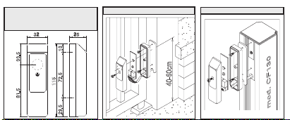
3) FITTING - They should be aligned and mounted at a height between 40 and 60 cm from the ground.The
surfaces used for fastening should be flat and parallel to each other.Mounting on pillar (fig. 1). Mounting
on CF130 post (fig. 2).If two pairs of photocells are mounted near each other, cross the RX-TX positions
(fig. 3).
4)TERMINAL BOARD
4.1) FL130 (fig.4) - Power supply 1(+) 2(-); 3-4 NO contact.
4.2) FL130B (fig.5) - Power supply 1(+) 2(-); contact NC 3-4, NO 3-5.
To connect the contacts, follow the instructions provided for the control devices used (control unit)
5) ALIGNMENT - Correctphotocellalignmentisobtained whenthelight of theRXreceiverLED(fig. 4-5) can
be seen after the cover has been fitted.When there is an obstacle between the RX receiver and the TX
transmitter, the LED goes off and the relay opens the contact.
GB
33.5
26
81.5
32
1372.529.5
115
DIMENSIONI- DIMENSIONS DI-
MENSIONS -ABMESSUNGEN
DIMENSIONES - DIMENSÕES
FIG.1
FIG.3
1) GÉNÉRALITÉS - Couple (émetteur-récepteur) avec double relais normalement excité à la sortie.
FL130 - En cas d’utilisation comme dispositif de “type D”, conformément à la norme EN 12453, prévoir
dans le plan de maintenance de la porte/portail un contrôle au moins tous les six mois.
FL130B - Peut être utilisé comme dispositif de “type D” conformément à la norme EN 12453 en le
reliant à une centrale de commande avec “CIRCUIT DE CONTROLE DES DISPOSITIFS DE
SÉCURITÉ”.
Ce produit est conforme aux normes reconnues de la technique et des dispositions en matière de
sécurité. Nous confirmons sa conformité aux directives européennes 89/336/CEE et aux modifications
successives.
2) CARACTÉRISTIQUESTECHNIQUES - Alimentation 20÷31 Vc.a / 22÷30Vdc; Puissance absorbée
couple 70 mA; Portée maxi 30 m (réduite en cas de brouillard-pluie); Contacts relais 1A à 24Vc.a.-c.d.
Température de fonctionnement -15° ÷ +70°C;Degré de protection IP54.
3) FIXATION - Elles doivent être fixées alignées à une hauteur comprise entre 40 et 60 cm du sol. Les
surfaces de fixation doivent être plates et parallèles entre elles. Montage sur pilier (fig. 1).Montage sur
colonne CF130 (fig. 2). Si on monte deux couples de cellules photo-électriques rapprochées, croiser
les positions RX-TX (fig. 3).
4) BORNIER
4.1) FL130 (fig.4) Alimentation 1(+) 2(-); 3-4 Contact NO.
4.2) FL130B (fig.5) Alimentation 1(+) 2(-); Contact NF 3-4, NO 3-5.
Pour connecter les contacts, suivre les indications des instructions des dispositifs de contrôle utilisés
(unité de commande).
5)ALIGNEMENT- L’alignementcorrectdescellulesphoto-électriquesestobtenulorsque,aveclecouvercle
monté, l’on entrevoit la Del du récepteur RX (fig. 4-5) allumée. En cas d’obstacle entre le récepteur RX et
l’émetteur TX, la Del s’éteint et le relais ouvre le contact.”
FIG.5
F
FIG.4
LED
NC
NO
5432
(VTX) 20-31V~
(VTX) 22-30V=
COM
20-31V~
22-30V=
RXTX
121
(+) (+)
LED
20-31V~
22-30V=
COM
PHOT
RXTX
4321
(+)
1 2
(+)
1) GENERALITA' - Coppia (trasmittente-ricevente) con doppio relè normalmente eccitato in uscita.
FL130 - Se usato come dispositivo di "Tipo D", secondo la norma EN 12453, deve essere prevista una
sua verifica almeno semestrale nel piano di manutenzione della porta/cancello.
FL130B - Può essere usato come dispositivo di "Tipo D" secondo la norma EN 12453, se collegato ad
una centralina con "CIRCUITO DIVERIFICA DEI DISPOSITIVI DI SICUREZZA".
Questoprodottorispondealle normericonosciute dellatecnicae delle disposizioni relativeallasicurezza.
É conforme alle seguenti direttive europee:89/336/CEE e modifiche successive.
2) DATITECNICI - Alimentazione20÷31Vac/ 22÷30Vdc;Assorbimento coppia70mA;Portata max 30m
(ridotta in caso di nebbia-pioggia); Contatti relè 1A a 24Vac-dc; Temperatura funzion. -15°C / +70°C;
Grado di protezione IP54.
3) FISSAGGIO - Devono essere fissate allineate ad una altezza compresa tra i 40-60cm dal suolo.
Le superfici di fissaggio devono essere piane e parallele tra loro. Montaggio a pilastro (fig.1).Montaggio
a colonna CF130 (fig.2). Nel caso vengano montate due coppie di fotocellule ravvicinate, incrociare le
posizioni RX-TX (fig.3).
4) MORSETTIERA
4.1) FL130 (fig.4) - Alimentazione 1(+) 2(-); 3-4 Contatto NO.
4.2) FL130B (fig.5) - Alimentazione 1(+) 2(-); Contatto NC 3-4, NO 3-5.
Per il collegamento dei contatti, attenersi a quanto indicato nelle istruzioni dei dispositivi di controllo
impiegati (centralina di comando).
5) ALLINEAMENTO - L'allineamento corretto delle fotocellule, è ottenuto quando, con coperchio mon-
tato, si intravede il LED della ricevente RX (fig.4-5) acceso. In presenza di ostacolo fra ricevente RX e
trasmittente TX, il LED si spegne ed il relè apre il contatto.
ISTRUZIONID'USOEDIINSTALLAZIONE
INSTALLATION AND USER'S MANUAL
INSTRUCTIONS D'UTILISATION ET D'INSTALLATION
INSTALLATIONS-UND GEBRAUCHSANLEITUNG
INSTRUCCIONES DE USOY DE INSTALACIONI
INSTRUÇÕES DE USO E DE INSTALAÇÃOIOON
FOTOCELLULA
PHOTOCELL
PHOTOCELLULE
PHOTOZELLE
FOTOCÉLULA
FOTOCÉLULA
Via Lago di Vico 44
36015SCHIO (VICENZA)
Tel.naz. 0445696511
Tel.int. +390445696533
Fax 0445696522
INTERNET www.bft.it
E-MAIL sales@bft.it
FL130 - FL130B
I
D811233 ver.05 06-03-07